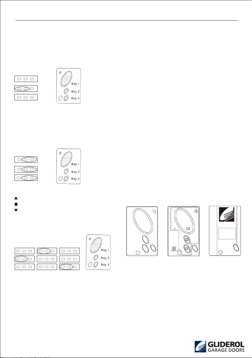
manuals.online logo
Brands
  1. Home
  2. •
  3. Brands
  4. •
  5. Gliderol
  6. •
  7. Door Opening System
  8. •
  9. Gliderol Glidermatic GRD Quick start guide

Gliderol Glidermatic GRD Quick start guide

Glidermatic GRD
Roller Door Automatic Operator
Installation Instructions and
GRD Owners Manual
TM
GLIDEROL
GARAGE DOORS
GRD-UK-001
Garage Doors Online
Garage Doors Online
01926 463 888
!
Glidermatic GRD
TM Roller Door Automatic Operator
IMPORTANT SAFETY INFORMATION -
PLEASE READ CAREFULLY
SAFELTY INSTRUCTIONS
WARNING! :-To reduce the risk of severe injury or death.
‧Never let children operate or play with the door controls.
‧Keep the remote control away from children.
‧Always keep the moving door in sight and away from people and objects until it is completely closed.
NO ONE SHOULD CROSS A MOVING DOOR.
‧Do not disengage the door opener to manual operation with children / persons or any other object including
motor vehicles within the doorway.
‧The g ara ge doo r mus t b e wel l b ala nce d. St icking or b ind ing doors c an fa lsely tri gge r t he ob str uct ion
sen sin g o f the G liderma tic U nit .
All maintenance should be carried out by suitably qualified personnel.
‧Test the door opener monthly. The garage door MUST reverse on contact with a 5 to 10 CM-High object on
the floor. The amount of force the door should encounter is adjustable. Failure to adjust the opener properly
may caus e severe injury or death.
‧T h e G R D O p e r a t o r h a s a p a t e n t e d e l e c t r o n i c o b s t r u c t i o n s y s t e m t h a t p r o v i d e s s a f e a n d r e l i a b l e
op er ation . It i s howe ve r a lega l requ ir em en t in s om e co un tr ie s to a ls o in st al l a Ph ot o- El ectri c se ns or
ac ro ss t he d oo r wa y; p le as e ch eck th is r eq uirem en t wi th y ou r lo ca l di st ri bu to r.
GRD OWNERS MANUAL PAGE 1
432
1
98
15
14 13
11
12
10
20
17 16
19 18 5
24
23
22 21
6
7
25
MANUAL GLIDERMATIC
Red Pin Handle
Geared Motor
Drum Wheel
Philips Screw
Main Gear Drive
Slip Ring
Wiring Loom
Brush Cover
Red Pin Handle
Split Ring
Anchor Tube
Anchor Block
Main Gear
Limit Switch `Down`
Limit Switch `Up`
Main Body Lid
Idler Gear (A)
Spacer Brush
Idler Gear (B)
Retain Washer
Cam Gear
Cam `Down`
Retain Washer
Cam `Up`
Keeper Plate
Main Body
1
2
3
4
5
6
7
8
9
10
11
12
13
14
15
16
17
18
19
20
21
22
23
24
25
Glidermatic Drive Assembly (Exploded View)
Fig1
Garage Doors Online
Garage Doors Online
01926 463 888
INSTALLATION INSTRUCTIONS
The installation instructions on this page relate to the installation
of an automatic operator on a roller door. If you have purchased a
roller door with a factory pre-assembled operator, please disregard
the operator installation procedures on this page.
These instructions are to be read in conjunction with Roller
Door Installation instructions.
Please note:-
TH E FO LL OW IN G IN ST RU CT IO NS F OR FI XI NG O F T HE
DRIVE UNIT ASSEMBLY TO THE DOOR ARE FOR A RIGHT-
HAND INSTA LLAT ION. ( Refe r t o F ig 1-8).
Check the door U-bolt is securely tightened on the LEFT hand
side of the door.
Raise the door and tie a rope around the center to secure the roll.
Support t he right hand end of the door with a suitable prop,
e.g. step ladder and soft padding to protect the door surface.
(Fig. 2)
STOP WARNI NG:- DO NOT ALLO W CH ILDREN / PEO PLE
AROU ND THE DOOR WHE N PROPOSED. SERIOUS
PERSO NAL INJU RY AND/OR PROPE RTY DAMAG E CAN
RESULT FROM FAIL URE TO FOLLOW TH IS WARNING .
Car efull y l oos en and re mov e the r igh t han d axle U- bol t.
d.
M a k e s u r e t h e d o o r s u p p o r t i n g p r o p i s s e c u r e . W h i l e
the door is supporte d,remove the right- hand wall mount
bra ck et. ( Fig . 3)
e.
Remove the geared motor (1) and from the packaging
material. Align the assembly with the lhree counter sunk
holes in the spoke section. Affix with screws supplied 3 X
(6x25mm counter sunk) using an appropriate flat bladed
screwdriver. (Ensure the motor assembly is securely
fixed to the drum wheel before proceeding.)
f.
R e m o v e t h e m o t o r s h a f t s c r e w a n d s l i d e o n t h e m a i n
driv e ge ar (4), th en refit the s haft scr ew and tig hten.
g.
Sl i de th e s lip ri ng as se m bl y ( 1 3) ov er th e d o or ax le ,
lo c at e i nt o a p os i ti on with t he two sl ip ri ng wire s are
cl o se s t to t h e mo t or. Co n ne c t th e t wo w i re s f ro m t he
sl i p r in g a s se mbl y t o t he mo t or le a ds . O b se rve th e
po l ar i ty o f t h e f ou r w ir e s i .e . r ed to re d , b la c k to b la ck .
h.
Three boss mount s on th e dr um wheel wi ll l ocate th e slip
ring assembly. Using the three self-tapping screws provided,
and securely fix into position (8 5/3).
i.
Slide the main Gear (12) over the door axle and engage teeth
with the motor drive gear.
j.
Sli de th e mai n b ody ( 25) o ver d oor a xle ,sp ace a nd make
sur e red p in ha ndl e(2 2) is in m anu al po sit ion . L oca te th e
con tac t bru she s ( 24) i nto i nne r and o ute r s lip r ing ( 13) .
k.
The main body should now be sitting flush up against the
rin g gear. Att ach s pli t rin g (9) t o spl it ri ng extr usi on an d
secure split Ring so tapping screw. (6 3/8)
l.
Replace right-hand side wall mount bracket. (Fig. 4)
m.
Remove support from the door and the rest axle carefully
on wall mounting bracket.
n.
GRD OWNERS MANUAL PAGE 2
Fig4
Fig3
Fig2
a.
b.
c.
Check if
'u' Bolt is
tihgtened
Rope
Romove
Right
'u' Bolt
Remove
Right
Bracket
Support
(Ladder)
Release Rope
Retighten
'u'Bolt
Refit
Right
Bracket
Remove
Support
(Ladder)
Garage Doors Online
Garage Doors Online
01926 463 888
Installation Instructions
Congratulations you have now successfully retrofitted your
Glidermatic drive unit. Please proceed to Control Box Set Up.
Sl id e an ti- co ni ng c ol la r ov er e ach e nd of s pi ndle at t he
opposite side of the door to the motor so that it is flush with
the edge of the split ring. Secure anti-coning collar tightly
to ensure it will not move. (Fig. 5)
o.
Push the anchor tubes through the anchor block and slide
the assembly over the wall bracket. Thread the drive unit
loom through the anchor tube and place the anchor tube
firmly into the female boss on the main body. Once in place,
lock the anchor tube and block it with the self-tapping screw
provided. (6 3/8) (Fig. 5)
p.
Realign the door and securely re-affix U-bolt.
q.
Place the weight bar provided on the bottom rail. Secure the
weight bar with the two spring clips provided 300mm from each
end of the weight bar. (Fig. 6) We also advise the use of silicone
in securing the weight bar in place before clips are fitted.
r.
Remove the control box from the packaging material; separate
the control box lid from the base by releasing the snap fit catch.
s.
Affix control box base securely to the garage wall at approxim-
ately head height. Connect drive unit loom to control box and
activate power.
t.
Setting the limits
Adjustment:-
Loosen the three locking screws within the cam assembly to
enable manual rotation of the cams.
Cam Down (21):-
This cam will rotate in the clockwise direction during the
downward travel. Adjustment is made so that when the door
is fully closed the cam has just activated the bottom limit switch.
Cam Up (23):-
This cam will rotate anti-clockwise during the upward travel.
Adjustment is made so that the cam activates the top limit
switch when the door has reached the desired height.
CAUTION: The up-cam should be set to stop the roller door
just below the guide stop to avoid jarring the drive gears etc.
Operate the control box push button several times to ensure
that the limit switches operate satisfactorily. Tightly secure
the cam retaining screws.
u.
Eng age G lider mat ic by s wit chi ng ma nua l rel ease pin t o
Automatic refer (Fig. 1).
Move the door manually until you hear pin engaged.
Activate Glidermatic by pressing push button on control box.
(Setting the Limits).
v.
Final Security -Fully close the door, mark the corrugation just
before the Curtain leaves the top roll, drill through the Curtain
and the Drum wheel rim,and apply a 'pop rivet' or self-tapping
screw. This must be done at both ends of the door (Fig. 8).
NOTE: After marking the flute, the curtain may be raised to
give access for drilling, etc.
WARNING: Care must be exercised when drilling to avoid
internal wiring.
w.
IMP ORTA NT: S ecurity rivet /tac k s cre w m ust
always be applied to inner side of drum wheel
as shown in Fig. 8A. Failure to do so may result
in internal damage to the Glidermatic drive unit.
GRD OWNERS MANUAL PAGE 3
The two cams shown (Fig. 7) set the length of door travel during
automatic operation. Ensure manual release pin is in manual
positiony state (Fig. 7) and that door moves freely in manual
operation.
Glidermatic operator should engage roller door and door travel
should be downwards. If 〝down〞 (21) cam has been set
correctly, the door should stop at floor level. Activate Gliderm-
atic-door should travel upwards and stop at desired height if
〝up〞 (23) cam is set correctly; door should travel upwards
and stop at desired height if 〝up〞 (23) cam is set correctly.
Fig5
Fig6
Fig7
Fig8
I f d o o r d o e s n o t s t o p a t d e s i r e d p o s i t i o n s , t u r n o f f
power and go back and readjust cams, as detailed above.
Anti Coning Collar
Safety Screw
Anchor
Bracket
Anchor
Tube
Lead
Control Box
Weight Bar
Bottom Rail
Locking Clip
Weather Seal
Cover removed
to show Cams
Inner Cam in 'Down'
Outer Cam in 'UP'
Automatic
Manual
Secure
Tek
Screw
A
A
Curtain
Tek Screw
Drum
Wheel
SECTION A-A
Drum Wheel
Tek Screw(Inner Sider)
Curtain
Garage Doors Online
Garage Doors Online
01926 463 888
Control Box Set Up (Fig. 9)
Adjust the Obstruction Detection Pot (4) to Maximum (Fully clockwise)
Open or close the door with the operation switch (6). Whilst the door is traveling turn the obstruction sensitivity
pot slowly anti-clockwise until an overload condition occurs ie. door going up stops before reaching the set top
limit or door going down auto-reverses before reaching set bottom limit.
Now adjust the pot 10 degrees in the clockwise direction.
Cycle the door a few times ensuring an overload condition is not registered during normal operation. If an
overload condition is registered, readjust the pot a further 10 degrees in the clockwise direction.
Installation Instructions
*S 2 J ump e r:
O n l y 1 〝0 . 0 5 o h m 5 w a t t r e s i s t o r〞 w i ll b e i n st a l l e d .
Fo r a ll re s ide ntia l door s, S2 Ju mper s hou l d be in t he pos itio n of S L
Fo r a ll co m mer cial d oors , S2 Jum per sh oul d b e in th e posi tion o f S L
(N o te: M u st be u sed in c onju ncti on wit h Pho t oce ll opt ion. )
GRD OWNERS MANUAL PAGE 4
Fig9
Fig10
Control Box
Push Button
Control Box Cover
Garage Doors Online
Garage Doors Online
01926 463 888
Transmitter Key and Code Setting
Refer to Fig. 9
Key Setting
Choose the Transmitter key configuration
(JP1/JP2/JP3) from the following:-
Single door installation (A)
Key 1
The above jumper configuration will allow Key 1 on
the hand transmitter to be programmed.
Note: The jumpers are located on the Control Box
Printed Circuit Board. (JP1, JP2, Jp3).
Single door installation (B)
Two or Three door installation
This above configuration uses all three keys.
Door 1
Jumper configuration for transmitter Key 1 only
Door 2
Jumper configuration for transmitter Key 2 only
Door 3
Jumper configuration for transmitter Key 3 only
Installation Instructions
Code Setting
Once the Key configuration is set you can now program
in the security code from your hand transmitter (s)
‧Press the learn code key once (8)
‧Learn LED indicator will light (8A)
‧Press the hand transmitter key that will operate the door
e.g.: for single door installation (A) you would press Key 1
‧Learn LED (8A) will go out
‧The hand transmitter is now programmed
Multiple Hand Transmitters
Repeat the above instructions for any subsequent Hand
Transmitters.
The Con trol Mod ule has en ough mem ory for up to 10
individual Hand Transmitters.
If more than 10 handsets are learnt the FIFO (First In
First Out) system applies i.e. first Hand Transmitter
code learnt will be deleted and replaced by the last Hand
Transmitter code learnt.
Deleting Hand Transmitters from Memory
Press and hold the learn code key (8)* for 5 seconds.
All transmitter codes held in the memory have been
erased.
Note: If a transmitter is lost or stolen, please erase the
memory and re-learn any spare or new transmitters.
Key Ring Transmitter
Battery Type 12V ALKILNE
The battery should be replaced every 12 months
To reassemble:-
‧Hold front cover as per drawing
‧Insert membrane, then Printed Circuit Board
(This will locate as per drawing)
‧Insert 12V ALKILNE Battery Positive towards screw
‧Locate back of the case and screw together
JP1
JP1
JP2
JP2
JP3
JP3
Up key 2
st op key 1
down k e y3
C/Box1 C/Box2 C/Box3
Inside of
Front
Cover
PCB Back
GRD OWNERS MANUAL PAGE 5
GLDEROL
GARAGE DOORS
GLDEROL
GARAGE DOORS
Garage Doors Online
Garage Doors Online
01926 463 888
CONGRATULATIONS! on the purchase of your Glidermatic Door Opener
The Glidermatic Roller Door has been granted the Individual Design Council of Australia Award. This award
reflects Gliderol Internationals commitment to continued advancement in technology and the use of the highest
quality components and materials. This ensures a highly reliable and quality assured product that should give
years of trouble free service.
DOOR OPERATION
A roller door equipped with a Glidermatic GRD opener
may be operated by any of the following three methods:-
(a) by using the handheld Transmitter.
(b) by depressing the push button on the control box.
(mounted on the garage wall)
(c) by an alternative bell press button, remotely hard
wired
Momentary activation of either of the above methods
will activate the door to open or close.
The door can be stopped at any point during travel by
a second activation of (a, b, or c). The following activ-
ation will move the door in the opposite direction.
INDEX
! WARNING
Ensure th at the Cen tr e Lift Loc k is not engaged
when the Drive Unit is in the automati c positio n.
Manual Operation
In the case of a power failure the Glidermatic drive unit has
an easily accessible manual release lever. Full instructions
are illustrated on the drive unit main body lid.
Obstruction Detection
During an open cycle if an obstruction is detected, the
door will stop.
During a closing cycle if an obstruction is detected, the
door will reverse to the open position. The sensitivity
or the amount force required to cause an obstruction
detection is fully adjustable.
Courtesy Light
An internal courtesy light is housed within the control box
enclosure. This is activated during an open or close cycle
and will stay illuminated for approximately 60seconds.
Automatic Closing
The Glidermatic can be programmed to automatically
close from 5 to 60 seconds after the door has been
opened.
Photo-electric sensor
The Glidermatic Operator includes an interface for the
connection of a photo-beam sensor.
The Photo-beam sensor can be supplied as an acce-
ssory option.
! WARNING
In some countries it is a legal requirement to fit
Photo-cell sensors. Please check with your local
distributor.
Audible Buzzer
The Glidermatic has an internal Piezo Siren that will
beep momentarily on each activation of the door.
This function can be disabled if required.
Rolling Code Security
The tr ans mitt er and r ecei ver in corpora te the lates t
state of the art encryption technology.
This allows the coded transmission to change after each
operation with literally billions of unique combinations.
Each Glidermatic unit has the facility to store up to 10
individual handsets.
Owner's Manual for the
Glidermatic GRD Roller Door Automatic Operator
GRD OWNERS MANUAL PAGE 6
TM
page page
Door Operation
Manual Operation
Obstruction Detection
Courtesy Light
Automatic Closing
Photo-electric Sensor
Audible Buzzer
Rolling Code Security
Key Ring Handset
Alarm Closure
Remote Switch
6
6
6
6
6
6
6
6
7
7
7
7
7
7
7
7
8
9
9
10
11
11
External Light
External Counter
Local Alarm
External LED Indicator
Operating Controls
Fault Table
Technical Specifications
Accessory Options
Warranty
Warranty Form
Sales & Service
Garage Doors Online
Garage Doors Online
01926 463 888
Key Ring Handset
The hand transmitter is manufactured using the latest
surface mount technology and incorporates 3 functional
buttons. This enables the user to remotely control up
to 3 separate operators from the one handset. The soft
touch silicon buttons have been impregnated with a
〝night glow〞 material for easier visibility.
Alarm Closure
If an attempt is made to force open the door from a
closed position, the Glidermatic Controller will pulse
operate the door to the fully closed position.
Remote Switch
A si mple B ell Pr ess typ e m omen tary switch can be
hard wired directly to the control board.
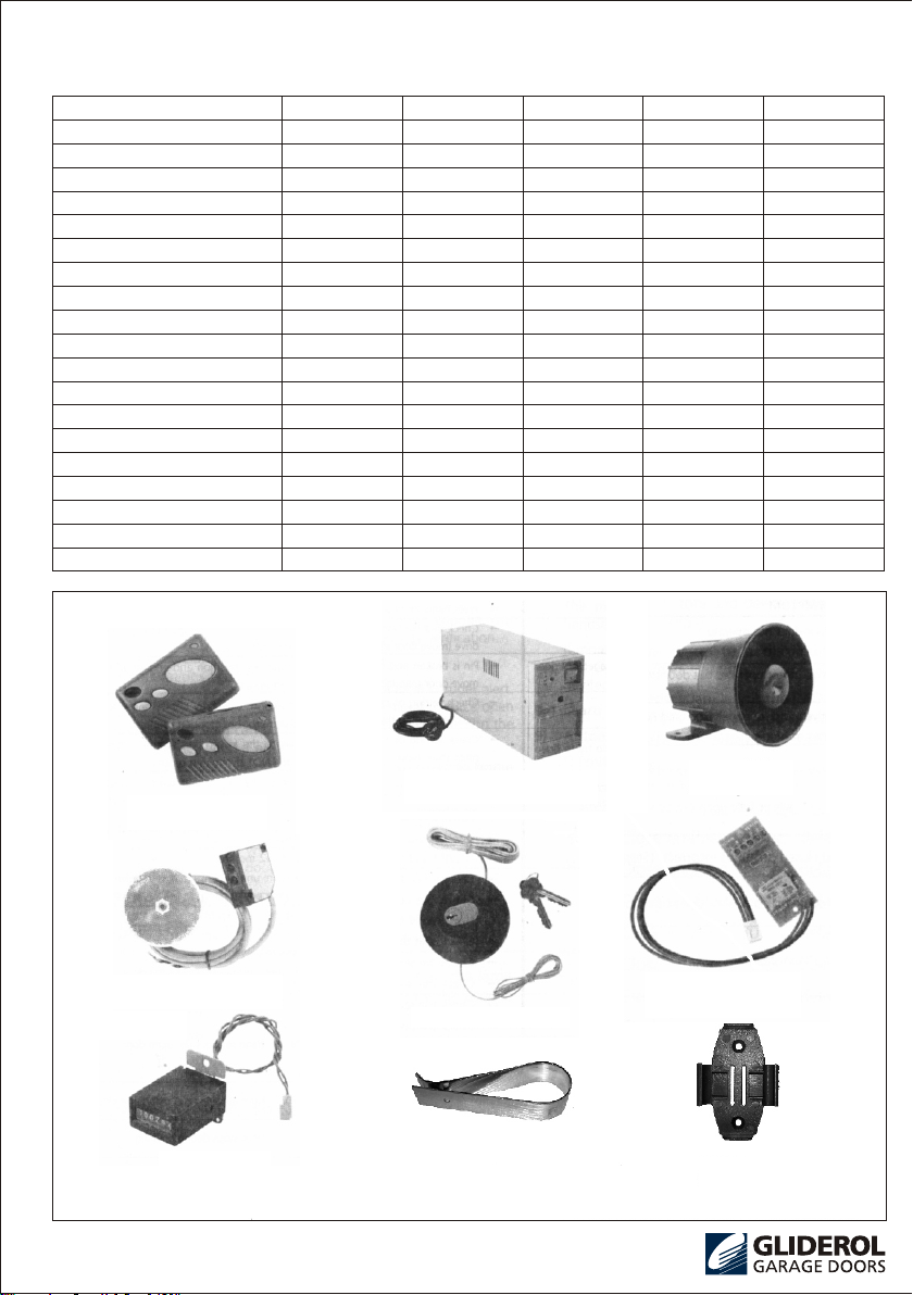
ACCESSORY OPTIONS
With the installation of a small accessory board, the
Gildermatic Controller can perform the following
functions:-
External Light
This a ccessor y o ption wil l allow the c onnecti on of
auxilia ry li ghting, i.e. dri ve wa y lig hti ng, i nter nal
garage lights.
NB: Max. Load 100W
! WARNING
All mains lighting must be fitted by a qualified Ele
ctrician / Personnel
External Counter
For commercial applications an electronic counter (for
door operations) can be used for warranty verification.
Local Alarm
A Piezo Alarm Siren can be fitted as a local intruder
alert. This will be activated if an attempt is made to
force open the door from the fully closed position. In
conjunction the door will perform an Alarm Closure.
This output can also be wired into an existing home
alarm system.
*Alarm closure as above.
External LED Indicator
An LED panel is fitted within the house (hard wired) to
show the status of the door i.e. opened or closed.
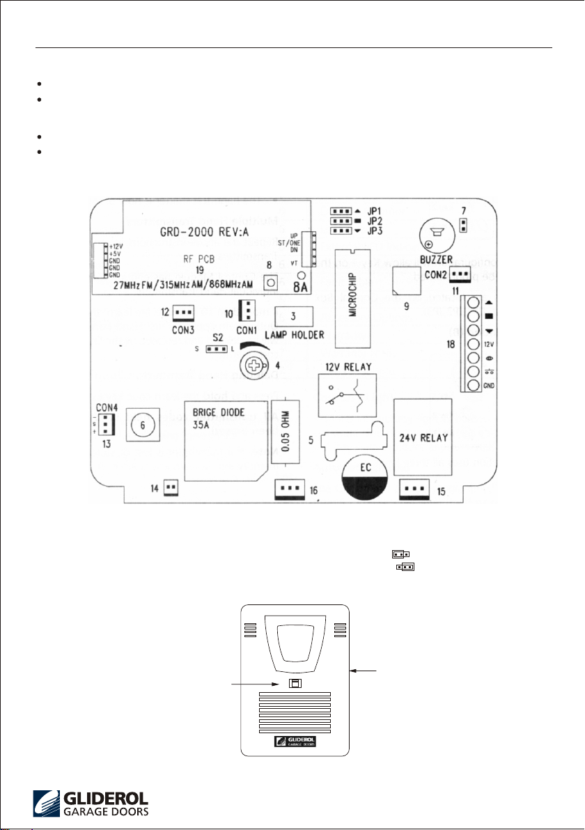
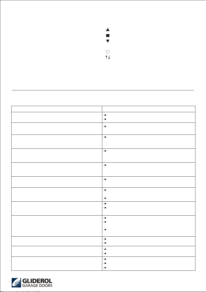
OPERATING CONTROLS (Fig. 9)
1)Control Box Push Button
Pressing this button will open, close, or stop the door.
2)Hand Transmitter
No min al ly fo r a si ng le d oor i ns tal la tion on ly t he
la rge e ll ipt ic al b utt on i s progr ammed t o op era te
th e do or, a m oment ar y pr es s of th is bu tto n w ill
open, close, or stop the door.
Note: The standard Glidermatic handset has three
fully functional and independent buttons. This allows
the hand set to operate up to three opener s,in the
Gliderol series ie Roller Door Opener,(GRD)Tilt and
Sectional Opener,(GTS)and the Commandoor 2 Gate
Opener.
3) Courtesy Lamp
This is a 9-Watt 24VDC Globe which is turned on after
each activation of the Control Box. The illumination
period is approximately 60 seconds.
4) Obstruction Detection (overload)
This adjustment pot allows you to increase or decrease
the amount force required on a moving door to register
an overload condition.
5) Fuse
This is an automotive blade type fuse.
15 A (Blue)
6) Operation Switch (During Set Up Only)
This PCB mounted switch will allow you to operate the
controller whilst the front cover has been removed,
enabling you to complete the set up adjustments and
test the unit.
7) Internal Piezo Buzzer (enable / disable)
The Piezo Buzzer is factory set in the enabled mode. To
disable remove the jumper pin (as shown in diagram 9)
8) Code Learning
This button is used to store and delete transmitter(s)
from the on board memory.
The memory will allow up to a maximum of 10 handsets
to be recorded.
If more than 10 handsets are learnt, the FIFO (First In
First Out) system applies, i.e. first code learnt will be
deleted and replaced by the latest code learnt.
8a) Learn LED Indicator
9) Automatic Close
O Position Auto Close disable.
1 Auto Close enabled 5 sec. delay
2 Auto Close enabled 15 sec. delay
3 Auto Close enabled 20 sec. delay
4 Auto Close enabled 30 sec. delay
5 Auto Close enabled 40 sec. delay
6 Auto Close enabled 50 sec. delay
7 Auto Close enabled 60 sec. delay
Please Note:
Time delay will start once the door has fully opened.
INTERNAL CONTROLS / CONNECTIONS
GRD OWNERS MANUAL PAGE 7
Garage Doors Online
Garage Doors Online
01926 463 888
Operating Controls (continued)
10) Con 1
External Light Accessory board connection
11) Con 2
External Alarm / Siren Accessory Board connection
12) Con 3
External LED Status Indicator Accessory Board
connection
13) Con 4
Front Cover Push Button connection
14) J5
External Counter connection
15) J1
Motor Loom connection
16) J4
Transformer connection (24VAC C/T)
17)JP1 / JP2/ Jp3
Transmitter button configuration (set up)
18)U9
Remote switch connection / Photocell connection
Up Direction
Stop
Down Direction
12 V DC
Photocell
UP, DOWN, STOP
Ground
19)Radio Receiver
This receiver is factory preset and has no user
adjustment.
SYMPTOM ACTION
Check electrical supply to unit.
Press hand set and/or bell press button again.
Check Red Pin Handle is in horizontal position and
engaged in drive (move door manually to re-engage).
Pin is broken and requires replacing. Check by
attempting the move door manually when the
motor has stopped running.
Check setting of cams relative to the upper limit
switch - unit must stop using the limit switch NOT
by striking ground.
Check setting of cams relative to the upper limit
switch - unit must stop using the limit switch NOT
by striking the guide top stop.
Adjust cams relative to the limit switches until
required positions are achieved.
Check that the Drive Unit is plugged in and motor
operates.
Check that the Red Pin Handle is engaged.
Replace handset battery after 12 months.
Check position of antenna on unit to ensure it is
relatively straight and not adjacent to the power cord.
Check power is switched on.
Check the fuse on circuit board and replace.
Check the door is not jammed in tracks.
12 V
GND
Before you call your local Gliderol agent please check the following Fault Table
Check the sensitivity setting on the circuit board.
Check the door is not jammed in tracks.
Check the sensitivity setting on the circuit board.
Check the door is not jammed in tracks.
Replace handset battery after 6-12 months.
Check position of antenna on unit to ensure it is
relatively straight and not adjacent to the power code.
Check that the handset has been programmed for
the door.
1. Door does not operate.
2. Drive motor operates but door does not move
4. Door auto-reverses after closing fully.
7. Courtesy light comes on but door does not move
8. Handset range diminishes.
9. Handset does not open the door.
10. Door auto-reverses before it is closed.
11. Door stops during opening.
3. Drive motor operates when Red Pin Handle is
engaged but door does not move.
5. Door stalls at fully open position and continues
to try to open the door if button is pressed again.
6. Door open and closed positions incorrect
(Stop short)
12. Door does not operate and the courtesy
lamp is not on.
GRD OWNERS MANUAL PAGE 8
Garage Doors Online
Garage Doors Online
01926 463 888
Technical Specifications
CHARACTERISTICS SYMBOL MIN TYP MAX UNIT
Control Box Standby Amp
Control Box Operating Amp
Input Voltage
System Power Dissipation
Transformer Power
Transformer Output Voltage
Work Voltage of Motor
Lamp Voltage
Buzzer Voltage
Fuse
Carrier Frequency Range
Modulation Mode
Deviation
RF Output Power
Transmitter Battery
Demodulation Mode
Receiver Sensitivity
Date Rate
Operational Temperature
J4
J1
LP1
BZ1
F1
Handset
Handset
Handset
Handset
Handset
RF
RF
RF
3
218
21.6
18
868.25
100
-90
-20
150
240
125
125
24
24
8
12
15A
868.35
AM
12
AM
1K
25
10
262
26.4
34
10
868.45
100
10
-100
85
mA
Amp
VAC
W
VA
VAC
VDC
W/DC2
VDC
A
MHZ
KHZ
uW
VDC
dBm
Hz
C
GRD OWNERS MANUAL PAGE 9
ACCESSOR Y OPTI ONS
Car Visor Clip Wall-Mount Cradle
Additional Remote
Control Transmitter
Uninterruptible Power Supply
in case of power failure
External Piezo
Security Alarm
Interface Board for
Optional extras
External Key & Switch
Photo Cell
Additional Safety Feature
External Counter
!WARNING All 240V connections must be fitted by qualified Electrician/Personnel
NB:Max.Load 100W
Garage Doors Online
Garage Doors Online
01926 463 888
The manufacturer, Gliderol Garage Doors Pty Ltd
(th e M an u f ac t u rer ) , a d i vi s i on o f G l i der o l
International Pty Ltd, of 32 Jacobsen Crescent,
Holden Hill, South Australia, 5088 warrants to
the original purchaser (the Vendee) that the
Glidermatic GRD (the Unit) including every major
component thereof will be free from defects in
materials and workmanship in normal operation
for a period of twelve (12) months from the date
of installation where installation is effected by the
Manufacturer or one of its Authorized Distributors
or otherwise from the date of purchase.
(1) Where the unit has been installed by the
Manufacturer or an Authorized Distributor, the
Manufacturer warrants such installation shall be
free from defects in material or workmanship and
hat the Vendee shall be entitled to free service by
the Manufacturer or its Authorized Distributors for
the purpose of adjustments and, in the opinion of
the Manufacturer not to remedy a defect to which
this Warranty relates will be paid for by the Vendee.
(2) Where the unit has not been installed by the
Manufacturer or its Authorized Distributor, in
addition to any warranty offered by the installer,
the Manufacturer will within twelve (12) months
after the date of purchase and after notification
of the defect by the Vendee and on the return of
the defective part of the unit repair or at its option,
replace any defective part of the unit without
charge provided disconnection, re-installation
and freight costs shall be borne by the Vendee.
Vendee to give Notification and Proof
The Vendee must immediately notify either the
Manufacturer or its Authorized Distributor in the
event of any alleged defect in the Unit and must
establish to the reasonable satisfaction of the
Manufacturer or its Authorised Distributo r the
date of purchase or installation (as the case may
be) by way of invoice or the completed Warranty
Form contained in this Manual.
Future Modification
The manufacturer reserves the right to modify any
existing or future models of the Unit without
incurring any obligation to incorporate such
modifications in Units already manufactured or to
which this Warranty may relate.
General
Subject to paragraph F and G the obligations of the
Manufacturer or its Authorized Distributor under this
Warranty are limited to those contained above and
this Warranty is the only warranty made by the
Manufacturer and exclusively and expressly in lieu
of all other warranties permitted to be excluded by
law whether these warranties are expressed,
implied, under common law or by statute and the
terms of the warranty may not be modified by person,
Warranty
G.Exclusions
Thi s War ra nty does no t ext end t o or affe ct th e
Man uf act ure r or its A uthor ize d Di str ibuto r in t he
eve nt t hat a ny de fe cts o r mal fu nct ion s of the Un it
are due to or result from:
1.Lack of proper care or maintenance of the Unit.
2.Incorrect, improper, or unreasonable use.
3.Faulty installatin or adjustment which is not carried
out by the Manufacturer or its Authorized Distributor.
4.Failur e to ob serve any instructio ns o r di rection s
provided with the Unit or given to the Vendee by the
installer.
5.Attempted modifications or repairs carried out by
any unauthorized person.
6.Faulty or unsuitable wiring of structures to which
the unit is affixed.
7.Ra dio ( inc lud ing c iti zen b and t ran smi ssi ons ) o r
any other electronic interference.
Subject to paragraph G it is expressly declared that
this Warranty does not apply to any batteries or bulbs
supplied with the Unit or with the changing of codes
on the Unit. globe
H.Statutory Warranties.
A.
B.
C.
D.
E.
F.
equivalent goods.
It is expressly provided that this Warranty or any
terms and conditions of it or any other literature
provided to the Vendee shall not be read or applied
so as to purport to exclude, restrict or modify or
have the effect of so doing the application in relation
to the supply of the Unit of all or any of the provisions
of division 2 and 2a of Part V of the Trade Practices
Act, 1974 (the Act) as amended or the exercise of a
right conferred by such provision or any liability of
the manufacturer or its Authorized Distributors for
breach of condition or warranty implied by such
provisions or any other condition or warranty implied
be any relevant State Act or Territorian Ordinance or
by the General Law and which by law cannot be
excluded, restricted or modified provided that to
the extent that the Act permits the Manufacturer to
limit his liability for a breach of condition or warranty
implied by the Act then the Manufacturer's liability
for such breach shall be limited to the payment of the
cost of replacing or repairing the goods or acquiring
Gliderol reserves the right to change or amend
product details or specifications without prior notice
as part of our continuous research and development
policy.
GRD OWNERS MANUAL PAGE 10
firm, or corporation other than the Manufacturer.
Garage Doors Online
Garage Doors Online
01926 463 888
Warranty Form
Name........................................ .....................Address..............................................................
.................................................................................................................................................
Unit Serial No................................................. Installation Date...................................................
Supplier (Distributor)..................................................................................................................
Installer...........................................................Phone No............................................................
Address.....................................................................................................................................
...................................................................................................................Installer's Signature
NOTE: THIS FORM MUST BE COMPLETED BY THE INSTALLER AND PRODUCED AS PROOF OF PURCHASE DATE
WHEN MAKING A SERVICE CALL UNDER WARRANTY, OTHERWISE SUCH CALLS ARE LIABLE TO SERVICE CHARGES.
This declaration of incorporation has been prepared by the garage door manufacturer of the Supply of Machinery
(Safety) Regulations(Machinery Directive) and signifies that the accompanying garage door operator, if installed
in accordance with the manufacturer's detailed instructions, will be suitable for use when attached to a garage door
with a compatible Declaration of Incorporation.
It is the responsibility of the installing company, to ensure that doors and garage door operators are currently matc-
hed prior to installation.It is also the responsibility of the installing company, legally described as the Responsible
Person, to ensure that a suitably nominated person will confirm that the power operated door has been installed in
accordance with the instructions provided by both the door and drive unit manufacturer.
It is also the responsibility of the installing company to check that the power operated door and any safety devices
provided are suitable for the application and are all working satisfactorily. This will permit the nominated person to
attach a CE label identifying the name of the installing company, unique door reference number and a date of com-
pletion, and to complete and issue a Declaration of Conformity (see note below).
One copy of the Declaration of Conformity is to be issued to the client and one copy to be retained by the installing
company, together with the relevant two Declarations of Incorporation. In accordance with the requirements of the
Machinery Directive and the UK Supply of Machinery (Safety) Regulations, these records are to be retained for a
period of ten years.
NOTE: Duplicate printed pads set out in format of Declaration of Conformity in order to allow on site completion are
available at a reasonable cost from Door Related Services on 01204 308196.
DECLARATION OF INCORPORATION
SUPPLY OF MACHINERY (SAFETY) REGULATIONS 1992
E.C. DECLARATION OF INCORPORATION
POWERED GARAGE DOOR OPERATOR
Gliderol Garage and Industrial Doors Limited
Davy Drive, North West Industrial Estate, Peterlee, Co. Durham SR8 2JF
Powered Garage
Door Operator Types... Glidermatic GRD
Roll‧A‧Matic GRD
The powered garage door operator models listed above are intended to be incorporated with a suitably designed
roller garage door (within specified size and weight limits) to provide powered operation. Samples of powered door
operators of the above types have been tested/checked and found to conform with the provisions of the Machinery
Directive. (80.392/EEC as amended by 91/368E, 93/44/EEC and93/68/EEC) the Low Voltage Directive (73/23/EEC)
and the EMC Directive (89/336/EEC).
A powered door operator must not be put into service until it has been completely and safely assembled and installed,
with an appropriate type, size and weight of door, in accordance with the door and operator manufacturer's instru-
ctions, using a suitable connection and appropriate safety devices etc., and not until the complete installation has
been declared to be in conformity with the provisions of the Machinery Directive.
The Technical File to cover the above mentioned power door operators is held by Gliderol Garage and Industrial
Doors Limited and will be made available at the request of the Enforcing Authority, should the need arise.
Gliderol Garage and Industrial Doors Limited
Head Office:
Davy Drive, North West Industrial Estate, Peterlee, Co. Durham SR8 2JF
Tel: 0191 518 0455 Fax: 0191 518 0548
Email: info@gliderol.co.uk Web: www.gliderol.co.uk
This declaration is made by:
Peter Newton
Company Secretary
Garage Doors Online
Garage Doors Online
01926 463 888

Other manuals for Glidermatic GRD

8

Other Gliderol Door Opening System manuals

Gliderol Glidermatic GTS+ Quick start guide

Gliderol

Gliderol Glidermatic GTS+ Quick start guide

Gliderol IGDU GEN II Upgrade Kit User manual

Gliderol

Gliderol IGDU GEN II Upgrade Kit User manual

Popular Door Opening System manuals by other brands

Bandini Industrie GI.BI.DI. FLOOR Series Instructions for installations

Bandini Industrie

Bandini Industrie GI.BI.DI. FLOOR Series Instructions for installations

B&S Smart Pro SDO-9V3 installation instructions

B&S

B&S Smart Pro SDO-9V3 installation instructions

DITEC DAS200TRF Technical manual

DITEC

DITEC DAS200TRF Technical manual

Salus SW600 quick guide

Salus

Salus SW600 quick guide

Dormakaba TENSOR Mounting instructions

Dormakaba

Dormakaba TENSOR Mounting instructions

Assa Abloy SW200 owner's manual

Assa Abloy

Assa Abloy SW200 owner's manual

Richmond GTR061 user manual

Richmond

Richmond GTR061 user manual

Dorma ED700 Installation and Tune In Manual

Dorma

Dorma ED700 Installation and Tune In Manual

Assa Abloy RD3 user manual

Assa Abloy

Assa Abloy RD3 user manual

DITEC GT Series Installation and maintenance manual

DITEC

DITEC GT Series Installation and maintenance manual

Assa Abloy Norton 6011 Series installation instructions

Assa Abloy

Assa Abloy Norton 6011 Series installation instructions

Videofied IDC 210 Product installation sheet

Videofied

Videofied IDC 210 Product installation sheet

Assa Abloy 1370 Mounting instructions

Assa Abloy

Assa Abloy 1370 Mounting instructions

Allstar J & H Series owner's manual

Allstar

Allstar J & H Series owner's manual

Mantion SLID'UP 2500 Instructions for assembly

Mantion

Mantion SLID'UP 2500 Instructions for assembly

Henderson MARATHON FDK1 Fitting instructions

Henderson

Henderson MARATHON FDK1 Fitting instructions

Versus-Omega PENTA CITY 300 user manual

Versus-Omega

Versus-Omega PENTA CITY 300 user manual

Assa Abloy Corbin Russwin PED5400 FE installation instructions

Assa Abloy

Assa Abloy Corbin Russwin PED5400 FE installation instructions

manuals.online logo
manuals.online logoBrands
  • About & Mission
  • Contact us
  • Privacy Policy
  • Terms and Conditions

Copyright 2025 Manuals.Online. All Rights Reserved.