Cool Ride PB-1 User manual

Lenkertaster
PB-1
Montage- und Betriebsanleitung
English version: see page 7

Wir beglückwünschen Sie
zum Kauf des Lenkertasters PB-1.
Lesen Sie diese Montageanleitung aufmerksam durch,
bevor Sie den Taster installieren. Die Montage erfordert
fortgeschrittene Kenntnisse der KFZ-Elektrik. Bitte neh-
men Sie den Anschluss nur dann vor, wenn Sie wissen,
was Sie tun. Wir empfehlen die Montage durch eine
Fachwerkstatt.
Falls noch Fragen offen sind, helfen wir gerne, diese zu
beantworten.
2

3
Der Lenkertaster PB-1 ist elektrisches Motorradzubehör. Es gibt ihn für metri-
sche Lenker mit einem Durchmesser von 22,23 mm sowie für zöllige Lenker mit
einem Durchmesser von 25,40 mm. Er weist eine Belastbarkeit von 50mA auf
und ist somit geeignet, ein Steuersignal von max. 50mA bereitzustellen. Der
Lenkertaster PB-1 ist die ideale Ergänzung zu unserem elektronischen Lastre-
lais SER-100, kann aber auch in Kombination mit anderen elektronischen Relais
oder Tastersteuerungen verwendet werden.
ACHTUNG: Schalten Sie mit dem Taster keinesfalls direkt einen Verbrau-
cher wie z.B. einen Zusatzscheinwerfer oder eine Hupe.
Nicht zur Verwendung an Geländefahrzeugen bzw. bei starker Schmut-
zeinwirkung geeignet. Nichtbeachtung dieser Hinweise führt zum Erlö-
schen der Garantie.
VERWENDUNGSBEREICH
Betriebsspannung: 3 – 32V DC (Gleichspannung)
Belastbarkeit: max. 50mA
Funktionsprinzip: einpoliger Schließer, Momentkontakt, Aus-(Ein)
Betriebstemperatur: -40°C – 85°C
Abmessungen: 15 x 12 mm (D x H)
Anschlussdrähte: je 600 mm lang
Wasser- und Staubschutz: partiell vergossen, IP67
Material: Aluminium, natur oder schwarz anodisiert
TECHNISCHE DATEN

4
• 1 Lenkertaster PB-1 mit 600 mm langen Anschlussdrähten
• 1 Kabelbinder schwarz 3,6 x 150 mm
• 1 Schrumpfschlauch schwarz 3,2 x 550 mm
LIEFERUMFANG
Ziehen Sie den Schrumpfschlauch über die Anschlussdrähte. Schrumpfen Sie
den Schrumpfschlauch auf der gesamten Länge oder nur am Ende, so dass die
farbigen Drähte verdeckt sind und der geschrumpfte Schlauch aus der Öff-
nung seitlich am Taster herausgeführt werden kann. Der Taster wird mittels
des beiliegenden Kabelbinders am Lenker montiert. Das Kabelbinderschloss
wird vorzugsweise nach unten gedreht, so dass es nicht zu sehen ist.
Bei der Wahl des Montageorts ist zu beachten, dass der Taster auch mit den
Händen an den Motorradgriffen gut zu erreichen ist.
Befestigen Sie den Kabelstrang in geeigneter Weise am Lenkerrohr, z.B. mit
Kabelbindern. Führen Sie alle elektrischen Verbindungen fachgerecht aus.
Auf die Kabel darf bei Montage und Betrieb keine übermäßige Belastung durch
Zug, Knicken oder Quetschen ausgeübt werden!
MONTAGE

ENTSORGUNG
Sollten Sie dieses Gerät eines Tages entsorgen müssen, be-
achten Sie bitte, dass elektronische Geräte nicht mit dem
Hausmüll entsorgt werden dürfen. Führen Sie das Gerät dem
Recycling zu. Ihre lokalen Behörden können Sie entsprechend
informieren.
EU-KONFORMITÄT
Dieses Produkt erfüllt die Anforderungen der geltenden
europäischen und nationalen Richtlinien. Die Konformität
wurde nachgewiesen, die entsprechenden Erklärungen und
Unterlagen sind beim Hersteller hinterlegt.
5
Wir gewähren 5 Jahre Garantie auf dieses Produkt. Schäden, die durch Nicht-
beachtung dieser Anleitung entstehen, sind ausgeschlossen. Es gelten die Ga-
rantiebedingungen unter www.coolride.de/Garantiebedingungen
GARANTIE
Der Lenkertaster ist weitgehend wartungsfrei. Reinigen Sie ihn bei Bedarf mit
einem feuchten, fusselfreien Tuch.
Sollte die Freigängigkeit des Tasters durch eingedrungenen Schmutz beein-
trächtigt sein, so können Sie ihn mit klarem Wasser ausspülen. Verwenden Sie
dazu eine Spritzflasche oder den Gartenschlauch, aber keinen Hochdruckrei-
niger. Betätigen Sie den Taster vorsichtig während des Ausspülens.
PFLEGE

COOLRIDE GmbH
Mangenberger Str. 150
42655 Solingen
Germany
Tel.: +49 212 / 235 70 69
Fax: +49 212 / 68 11 06 94
www.coolride.de
Änderungen, Druckfehler & Irrtum vorbehalten.
Abbildungen sind unverbindlich.
6

Handlebar Switch
PB-1
Operation manual
7

Congratulations to your new Handlebar Switch PB-1.
Please read these instructions carefully before any
attempt of installation. The installation requires advan-
ced knowledge in vehicle electrics. We recommend ins-
tallation by a specialist workshop.
If there are any questions unanswered, please contact
us. We are happy to help.
8

9
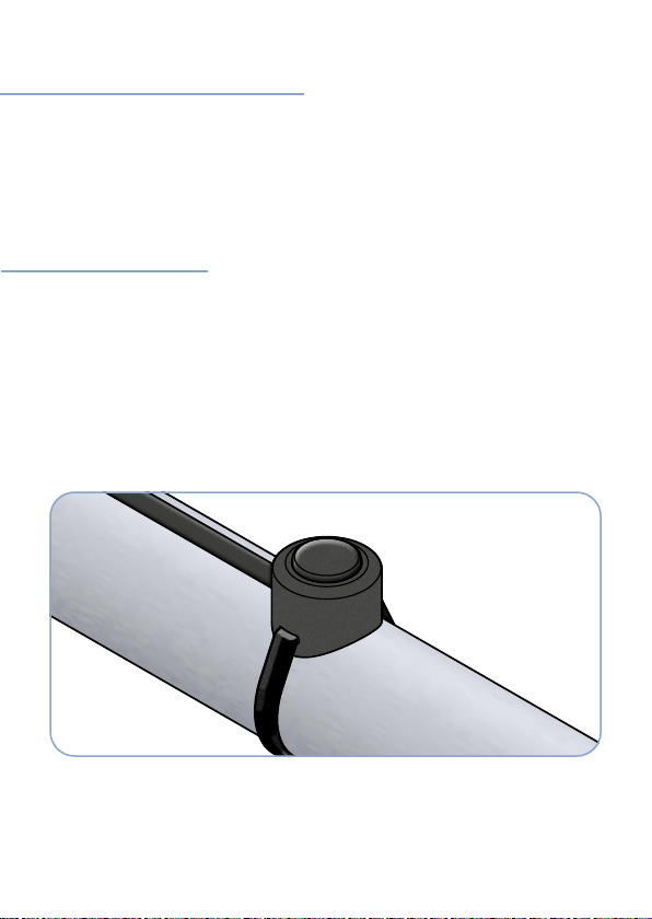
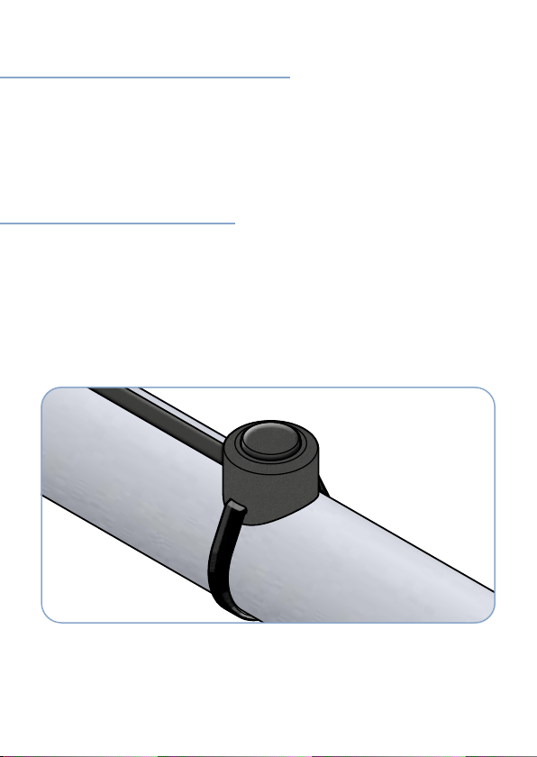
The handlebar switch PB-1 is electric motorcycle accessory. It is available for
metric handlebars with a diameter of 22.23 mm and for imperial handlebars
with a diameter of 1 inch / 25.40 mm. It has a load capacity of 50mA and is the-
refore suitable to provide a control signal of max. 50mA. The handlebar switch
PB-1 is the ideal complement to our electronic load relay SER-100 but can also
be used in combination with other electronic relays or button control units.
CAUTION: Do not use the button to switch a load such as an auxiliary
light or a horn directly.
Not suitable for use on off-road vehicles or when exposed to heavy dirt.
Use only on motorcycles, trikes, quads etc. with 12V electrical system.
Disregard of these instructions will cause loss of warranty.
FIELD OF APPLICATION
Operating voltage: 3 - 32V DC
Load capacity: max. 50mA
Principle of operation: single pole normally open, momentary contact, off (on)
Operating temperature: -40°C – 85°C / -40°F - 185°F
Measurements: 15 x 12 mm (D x H) / 0,6 x 0,47 inches (D x H)
Connection wires: 600 mm / 23,6 inches each
Water / dust protection: partially encapsulated, IP67
Material: Aluminium, natural or black anodized
TECHNICAL DATA

10
• 1 handlebar switch PB-1 with 600 mm leads
• 1 black zip tie 3.6 x 150 mm
• 1 black heat shrink tubing 3.2 x 550 mm
SCOPE OF SUPPLY
Pull the heat shrink tubing over the leads. Shrink the heat shrink tubing along
the entire length or only at the end so that the coloured wires are covered and
the shrunk tubing can be led out of the notch on the side of the button. The
button is mounted on the handlebar using the zip tie provided. The zip tie lock
is preferably turned down so that it cannot be seen.
When choosing the installation location, make sure that the button can easily
be reached with your hands on the motorcycle handles.
Fasten the cables to the handlebar tube in a suitable manner, e.g. with zip ties.
Carry out all electrical connections properly.
During assembly and operation, the cables must not be subjected to excessive
stress by pulling, sharp bending, or squeezing!
INSTALLATION

DISPOSAL
Should you need to dispose of this system someday, please
note that electronic devices must not be disposed of with
household waste. If possible, recycle the item. Your local au-
thorities can inform you accordingly.
EC-CONFORMITY
This product complies with the requirements of applicable
European and German directives. Conformity has been ve-
rified, the corresponding declarations and documents are
deposited with the manufacturer.
11
We grant a full 5-year warranty on this product. Damage resulting from over-
load or disregard of the herein given advise is excluded. Warranty conditions
apply as available at www.coolride.de/warranty
WARRANTY
The handlebar button is maintenance-free to a great extent. If necessary, cle-
an it with a damp, lint-free cloth.
If the freedom of movement of the button is impaired by dirt that has penetra-
ted it, you can rinse it out with clear water. Use a squirt bottle or garden hose,
but not a pressure washer. Carefully press the button while rinsing.
CARE

COOLRIDE GmbH
Mangenberger Str. 150
42655 Solingen
Germany
Phone: +49 212 / 235 70 69
Fax: +49 212 / 68 11 06 94
www.coolride.de
Changes, misprints & errors excepted.
Illustrations are not binding.
12
Table of contents
Languages:
Popular Motorcycle Accessories manuals by other brands

hepco & becker
hepco & becker 8006519 00 01 quick start guide

Corbin
Corbin KV-900-6-BAG quick guide

hepco & becker
hepco & becker 650.2514 00 01 Assembling instructions

IonGear
IonGear 5637 operating instructions

Memphis Shades
Memphis Shades MEM-9909 Mounting instructions

hepco & becker
hepco & becker 6307546 00 01 Mounting instructions