DOC-005 Iss 15 4
2. Safety Precautions
While LEDs are a much safer illumination system than the mercury and
metal halide lamps that they replace in microscopy applications, precautions
should still be taken with this product.
When operating or maintaining this product, please observe the following
safety precautions at all times. Failure to do so may result in personal injury
or damage to other items.
Please ensure that only the power supply and cord supplied are used with
this equipment.
The AC cord supplied with this light source must only be used with the
equipment supplied.
2.1.
UV light may be emitted from this product depending on the
version/wavelength selected. Avoid eye and skin exposure. Never look
directly into the light output beam from the Light Source or accessories. The
emissions could damage the cornea and retina of the eye if the light is
observed directly.
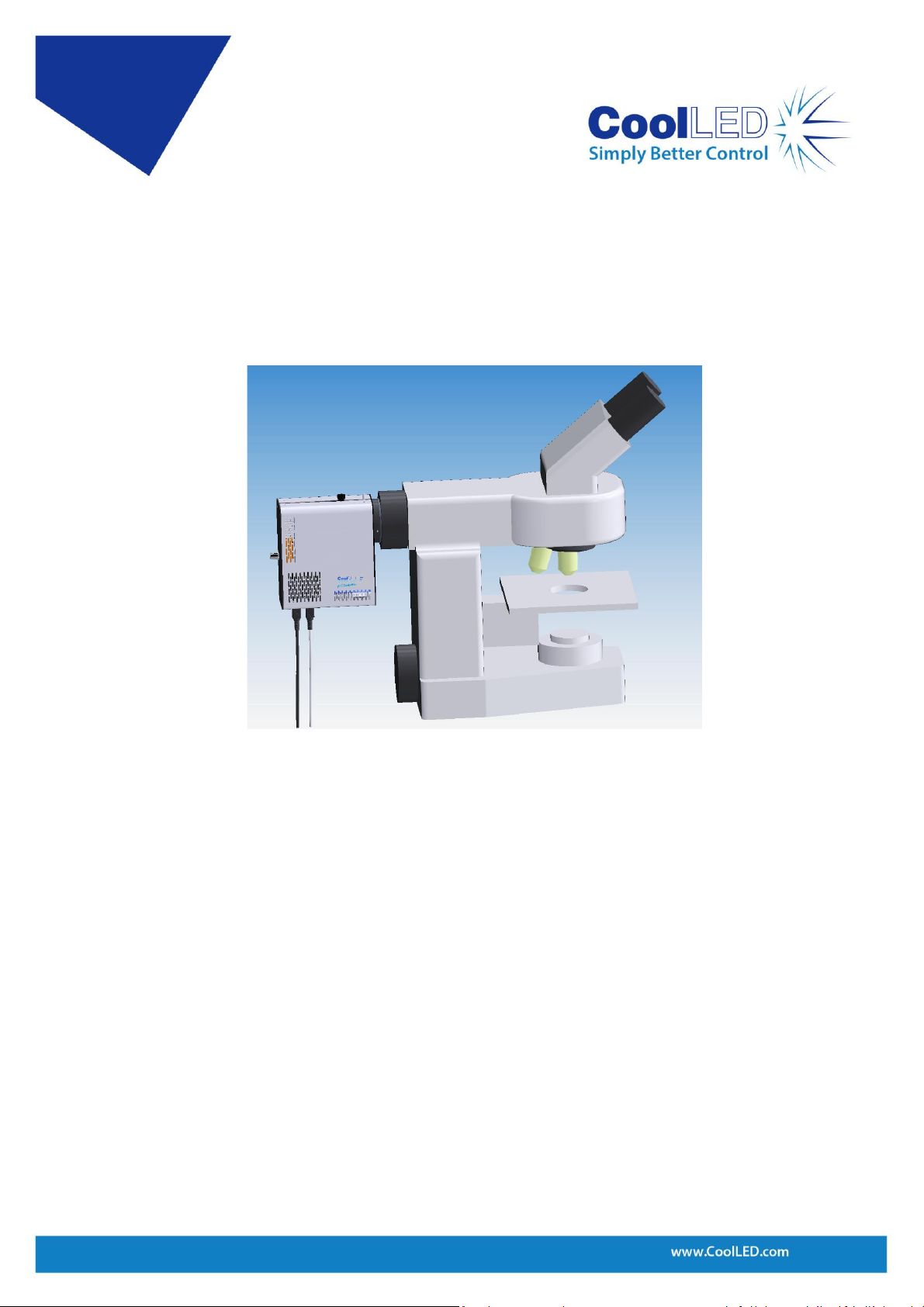
2.2.
Always ensure that the Light Source is securely attached to the microscope
(either directly or with a light guide and collimator, depending on the
version) prior to turning on the power. This will minimise the risk of injury
and damage.
2.3.
If for any reason the Light Source is to be operated when not attached to a
microscope, all personnel should wear eye shielding and clothing to protect
the exposed skin.
2.4.
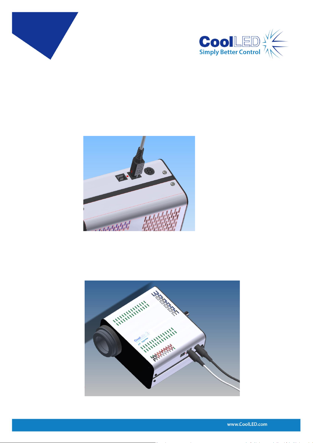
Disconnecting the mains supply is achieved by unplugging the power cord
from the power supply block or the Light Source. Only plug in the power
cable, once the Light Source is attached to the microscope.
2.5.
There are no serviceable parts within the Light Source. Removing any of the
screws and covers will result in the safety of the Light Source being impaired.
The DC power supply unit should be inspected periodically throughout the
lifetime of the system.