manuals.online logo
Brands
  1. Home
  2. •
  3. Brands
  4. •
  5. Utilitech
  6. •
  7. Lighting Equipment
  8. •
  9. Utilitech CMG-NYC-M3 User manual

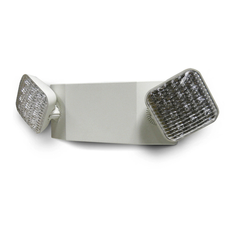
Utilitech CMG-NYC-M3 User manual

-
+
BLACK
BLACK
BLACK
RED
RED
BLACK
WHITE
VIOLET
VIOLET
VIOLET
YELLOW
RED
TRANSF
LED BOARD
BLUE
YELLOW
YELLOW
Star washer
Nut
277 VOLT
120 VOLT
COMMCHARGER
BOARD
LAMPLAMP
To Remote LAMP
SWITCHAC ON
BATTERY
NYC-APPROVED LED EXIT/
EMERGENCY COMBO SIGN
LETRERO COMBINADO DE
SALIDA Y EMERGENCIA CON LUZ
LED APROBADO EN NUEVA YORK
ITEM/ARTÍCULO #0122176
MODEL/MODELO: CMG-NYC-M3
PACKAGE CONTENTS / CONTENIDO DEL PAQUETE
HARDWARE CONTENTS / ADITAMENTOS
A
AA BB
x 1
x 2
-
+
BLACK
BLACK
BLACK
RED
RED
BLACK
WHITE
VIOLET
VIOLET
VIOLET
YELLOW
RED
TRANSF
LED BOARD
BLUE
YELLOW
YELLOW
Star washer
Nut
277 VOLT
120 VOLT
COMMCHARGER
BOARD
LAMPLAMP
To Remote LAMP
SWITCHAC ON
BATTERY
x 1
AB13112
Utilitech and UT Design® is a registered trademark of LF, LLC. All Rights Reserved.
Utilitech® es una marca comercial registrada de LF, LLC. Todos los derechos reservados.
TROUBLESHOOTING / SOLUCIÓN DE PROBLEMAS
1. The emergency lights DO NOT operate and:
a. If the charge indicator light is OFF = Check that the circuit breaker for AC supply is ON.
b. If the charge indicator light is ON:
- Check that the battery is properly connected.
- If remote lamps are connected to the equipment, then turn OFF the AC supply and disconnect the remote circuit wires from the
equipment. Turn ON the AC supply and depress the test switch. If the local lamps (mounted on the equipment itself) come ON, then
check the remote circuit for short or overload condition and correct as required. Reconnect the circuit wires and restore AC power.
- If the local lamps don't turn ON after disconnecting the remote circuit wires, then replace battery.
Las luces de emergencia NO funcionan y:
a. Si la luz indicadora de carga está APAGADA = compruebe que el interruptor de circuito para suministro CA esté ENCENDIDO.
b. Si la luz indicadora de carga está ENCENDIDA:
- Compruebe que la batería esté conectada de forma correcta.
- Si las lámparas remotas están conectadas al equipo, APAGUE el suministro de CA y desconecte los conductores del circuito remoto
del equipo. ENCIENDA el suministro de CA y presione el interruptor de prueba. Si las lámparas locales (montadas en el equipo
mismo) se ENCIENDEN, revise si hay un cortocircuito o una sobrecarga en el circuito remoto y corrija según sea necesario. Vuelva
a conectar los conductores del circuito y restablezca el suministro de CA.
- Si las lámparas locales no se ENCIENDEN luego de desconectar los conductores del circuito remoto, reemplace la batería.
2. Emergency lights are dim = implies battery might not be fully charged. Allow battery to recharge for 24 hours and then re-test.
Las luces de emergencia son tenues = implica que la batería puede no estar completamente cargada.
Deje que la batería se recargue durante 24 horas y vuelva a probar.
WARRANTY / GARANTÍA
CARE AND MAINTENANCE / CUIDADO Y MANTENIMIENTO
5-Year Warranty All products are warranted to be free from defects in material and workmanship. The obligation is expressly limited to repair or replacement, without
charge, at the factory after prior written return authorization has been granted. This warranty shall not apply to products which have been altered or repaired outside of the
factory. This warranty is in lieu of all other warranties, expressed or implied, and without limiting the generality of the foregoing phrase, excludes any implied warranty of mer-
chantability. Also, there are no warranties which extend beyond the description of the product on the company’s literature setting forth terms of sale.
5 años de garantía: Se garantiza que todos los productos están libres de defectos en los materiales y la mano de obra. La obligación se limita expresamente a la repara-
ción o el reemplazo del producto, sin cargo y en la fábrica, una vez que se haya otorgado una autorización de devolución por escrito. Esta garantía no se aplica a productos
que hayan sido alterados o reparados fuera de la fábrica. Esta garantía reemplaza a todas las demás garantías, explícitas o implícitas, y sin prejuicio de la generalidad de lo
mencionado anteriormente, excluye toda garantía implícita de comerciabilidad. Además, no existen garantías que se extiendan más allá de la descripción del producto en el
material impreso por la empresa en el que se especican las condiciones de venta.
CAUTION: Always turn OFF AC power to the equipment before servicing. Servicing should be performed only by a qualied service technician. Only manufacturer
SUPPLIED or APPROVED replacement parts must be used.
PRECAUCIÓN: Siempre APAGUE la alimentación de CA en el equipo antes de realizar mantenimiento. Solo un técnico calicado puede realizar mantenimiento
esta unidad. Use solo piezas de repuesto SUMINISTRADAS o APROBADAS por el fabricante.
The battery in this unit may not be fully charged. After electricity is connected to unit, let the battery charge for at least 12 hours. To check battery, press TEST but-
ton. The sign should illuminate. The battery supplied with this unit requires ZERO maintenance. However it should be tested periodically and replaced when it no
longer operates the connected xtures for the complete duration of a 30-second or 90-minute test. NFPA 101 (Life Safety Code) requires that all emergency lighting
equipment be functionally tested every 30 days for a minimum of 30 seconds and tested annually for full 90-minute duration. Written records of the testing are to be
kept for examination by the authority having jurisdiction. It has a life expectancy of 5-7 yrs when used in a normal ambient temperature of 72°F.
Es posible que la batería de esta unidad no esté completamente cargada. Después de conectar la electricidad a la unidad, deje que la batería se cargue durante
12 horas como mínimo. Para comprobar el estado de la batería, presione el botón TEST (Prueba). La señal debe iluminarse. La batería que se incluye con esta
unidad NO requiere mantenimiento. Sin embargo, debe probarse periódicamente y reemplazarse cuando ya no haga funcionar las lámparas conectadas durante
toda la prueba de 30 segundos o 90 minutos. El NFPA 101 (código de seguridad humana) exige probar la funcionalidad de todos los equipos de luces de emergen-
cia cada 30 días por un mínimo de 30 segundos, y anualmente por la duración completa de 90 minutos. Se deben mantener registros escritos de las pruebas a n
de que la autoridad con jurisdicción los examine. Tiene una vida útil esperada de 5 a 7 años si se usa a una temperatura ambiente normal de 22,2 °C.
Clean lenses and replace lamps as, and when, required.
Limpie las micas y reemplace las lámparas según, y cuando, sea necesario.
Printed in China / Impreso en China
PREPARATION / PREPARACIÓN
INSTALLATION INSTRUCTIONS / INSTRUCCIONES DE INSTALACIÓN
Before beginning installation of product, make sure all parts are present. Compare parts with package contents list and
hardware contents list. If any part is missing or damaged, do not attempt to assemble, install or operate the product.
Estimated Assembly Time: 20 minutes
Tools Required for Assembly (not included): Flathead screwdriver, Phillips screwdriver, Drill with 1/4 in. drill bit
Antes de comenzar a instalar el producto, asegúrese de tener todas las piezas. Compare las piezas con la lista del contenido del paquete y la lista de
aditamentos. No intente ensamblar, instalar ni usar el producto si falta alguna pieza o si están dañadas.
Tiempo estimado de ensamblaje: 20 minutos
Herramientas necesarias para el ensamblaje (no se incluyen): Destornillador de cabeza plana, destornillador Phillips, taladro con broca para taladro de ¼ pulg
1
.
Be certain power is shut off to conduit before installation.
Asegúrese de cortar la alimentación a los conductos antes de la
instalación.
2. Remove retainer screw from bottom of sign, then slide out front face
plate and place in safe location during installation.
Retire el tornillo retenedor de la parte inferior del letrero, luego
deslice la placa frontal hacia afuera y colóquela en un lugar seguro
durante la instalación.
3. Remove internal metal reector plate by removing the two screws.
Retire la placa del reector de metal interno retirando los dos tornillos.
4. Knock out the appropriate mounting
pattern on back of unit to attach to
junction box. Feed electrical wires into
unit. There are two additional KEY
HOLE slots located on the top of the
unit. These holes must be used when
the unit is mounted to the wall.
Haga agujeros con el diseño de montaje apropiado en la parte
posterior de la unidad para jarla a la caja de unión. Haga pasar
los conductores eléctricos hasta dentro de la unidad. Existen dos
ranuras EN FORMA DE CERRADURA adicionales ubicadas en la
parte superior de la unidad. Estos agujeros deben usarse cuando la
unidad se monta en la pared.
5. Secure sign to junction box using two 1-1/2 inch screws (AA).
Fije el letrero a la caja de unión usando dos tornillos de 1 1/2 pulg (AA).
6.
Connect ground in accordance with local
building code. Connect wires per schem-
atic and color code as follows:
277V = RED
120V = BLACK
NEUTRAL = WHITE
Cap unused line lead with wire nut (BB).
Conecte la puesta a tierra de acuerdo con el código de construcción
local. Conecte los conductores de acuerdo con el código esquemáti-
co y de colores de la siguiente manera:
277 V = ROJO
120 V = NEGRO
NEUTRO = BLANCO
Tape el terminal de la línea que no utilice con el empalme plástico (BB).
7. Connect the Red and Blue leads from
the circuit board to the battery
terminals.
Red lead +
Blue lead -
Note: After hardwire electricity is
restored, battery may take up to
24 hours to fully charge.
Conecte los terminales rojo y azul del
tablero de circuitos a los terminales de la batería.
Terminal rojo +
Terminal azul -
Nota: Cuando restablezca la electricidad al circuito principal, la batería
puede necesitar hasta 24 horas para cargarse por completo.
8.
Replace the internal metal reector and secure to unit with the two
screws.
Reemplace el reector de metal interno y fíjelo a la unidad con los dos
tornillos.
9. Carefully replace front panel and lens to the sign and secure
bottom screw.
Con cuidado vuelva a colocar el panel frontal y la mica al letrero y
apriete el tornillo inferior.
10. Restore AC power to conduit and press and hold the test button.
The lamps will illuminate as long as you hold depress the button.
The EXIT sign will remain illuminated. CAUTION: This equipment is
furnished with a sophisticated solid state transfer switch which will
automatically disconnect the emergency lights from the battery if the
battery has been discharged to the end of its useful output.
Restablezca la alimentación de CA a los conductos y mantenga pre-
sionado el botón de prueba. Las lámparas se iluminarán siempre que
mantenga presionado el botón. El letrero de SALIDA permanecerá
iluminado. PRECAUCIÓN: Este equipo cuenta con un sosticado
interruptor de transferencia de estado sólido que desconecta au-
tomáticamente las luces de emergencia de la batería si esta se ha
descargado hasta el n de su vida útil.
-
+
BLACK
BLACK
BLACK
RED
RED
BLACK
WHITE
VIOLET
VIOLET
VIOLET
YELLOW
RED
TRANSF
LED BOARD
BLUE
YELLOW
YELLOW
Star washer
Nut
277 VOLT
120 VOLT
COMM
CHARGER
BOARD
LAMPLAMP
To Remote LAMP
SWITCHAC ON
BATTERY
6
-
+
BLACK
BLACK
BLACK
RED
RED
BLACK
WHITE
VIOLET
VIOLET
VIOLET
YELLOW
RED
TRANSF
LED BOARD
BLUE
YELLOW
YELLOW
Star washer
Nut
277 VOLT
120 VOLT
COMM
CHARGER
BOARD
LAMPLAMP
To Remote LAMP
SWITCH
AC ON
BATTERY
7
B AT.
L E D B O A R D
P O W E R
B O A R D
W H I T E C O M
O R A N G E 1 0 0 - 3 0 0 V A C
P O W E R
B O AR D
W H I T E C O M
O R A N G E 1 0 0 - 3 0 0 V AC
L E D B O AR D
4
SAFETY INFORMATION / INFORMACIÓN DE SEGURIDAD
Please read and understand this entire manual before
attempting to assemble, operate or install the product.
• Do not use outdoors.
• Do not mount near gas or electric heaters.
• Use caution when handling battery back-up.
• Mount equipment in locations and at heights that will
avoid tampering by unauthorized personnel.
• The use of accessory equipment not recommended by the manufacturer
may cause an unsafe condition.
• Turn OFF electricity at fuse or circuit breaker before wiring power supply.
• Do not use equipment for anything other than intended use.
• Consult local building code for approved wiring and installation.
• Installation and servicing should be performed by qualied personnel only.
SAVE THESE INSTRUCTIONS
Lea y comprenda completamente este manual antes
de intentar ensamblar, usar o instalar el producto.
• No lo use en exteriores.
• No lo instale cerca de calentadores eléctricos o a gas.
• Tenga cuidado al manipular la batería de reserva.
• Instale el equipo en un lugar y a una altura que eviten
la manipulación por parte de personal no autorizado.
• El uso de equipos accesorios no recomendados por el fabricante puede
crear condiciones inseguras.
• Corte la electricidad en la caja de fusibles o en el interruptor de circuito
antes de cablear el suministro de electricidad.
• No utilice este equipo para ningún otro n que no sea el especicado.
• Consulte el código de construcción local para conocer la instalación y el
cableado aprobados.
• La instalación y las reparaciones solo debe realizarlas personal calicado.
GUARDE ESTAS INSTRUCCIONES
RED/ROJO
RED
ROJO
BLUE
AZUL
BATTERY
BATERÍA
TRANSF
277V
120V
COMM/COM
BLACK/NEGRO
WHITE/BLANCO
CHARGER
BOARD
TABLERO
DEL
CARGA-
DOR

This manual suits for next models

1

Other Utilitech Lighting Equipment manuals

Utilitech UC1139-WHG-12LF0-U User manual

Utilitech

Utilitech UC1139-WHG-12LF0-U User manual

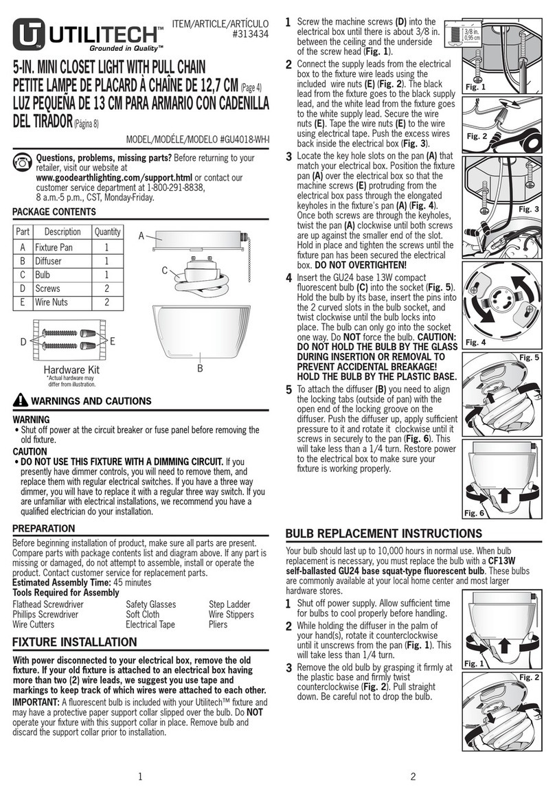
Utilitech GU4018-WH-I User manual

Utilitech

Utilitech GU4018-WH-I User manual

Utilitech UT-5666-AL User manual

Utilitech

Utilitech UT-5666-AL User manual

Utilitech UC1025-WHG-21T81-U User manual

Utilitech

Utilitech UC1025-WHG-21T81-U User manual

Utilitech FSI UT-201-1200BRZ User manual

Utilitech

Utilitech FSI UT-201-1200BRZ User manual

Utilitech FSI UT-201-2000BWHT User manual

Utilitech

Utilitech FSI UT-201-2000BWHT User manual

Utilitech 6334 User manual

Utilitech

Utilitech 6334 User manual

Utilitech GU8923-BZ-I User manual

Utilitech

Utilitech GU8923-BZ-I User manual

Utilitech CMG-113-R User manual
Utilitech

Utilitech CMG-113-R User manual

Utilitech DLS30-06F27D1E-WH-F1 User manual

Utilitech

Utilitech DLS30-06F27D1E-WH-F1 User manual

Utilitech PLWK432WAR8 User manual

Utilitech

Utilitech PLWK432WAR8 User manual

Utilitech UT1042S User manual

Utilitech

Utilitech UT1042S User manual

Utilitech E70HUT User manual

Utilitech

Utilitech E70HUT User manual

Utilitech AC1050-AL3-03LF1-U User manual

Utilitech

Utilitech AC1050-AL3-03LF1-U User manual

Utilitech UC1015-WH1-30LF0-U User manual

Utilitech

Utilitech UC1015-WH1-30LF0-U User manual

Utilitech GU8813-BZ-I User manual

Utilitech

Utilitech GU8813-BZ-I User manual

Utilitech CMG-103 User manual

Utilitech

Utilitech CMG-103 User manual

Utilitech 0009-0008 User manual

Utilitech

Utilitech 0009-0008 User manual

Utilitech UC1011-WHG-16LF0-U User manual

Utilitech

Utilitech UC1011-WHG-16LF0-U User manual

Popular Lighting Equipment manuals by other brands

HALTO KEPLER 150 quick start

HALTO

HALTO KEPLER 150 quick start

Avlite AV-70 Installation & service manual

Avlite

Avlite AV-70 Installation & service manual

Velvet Light Series user manual

Velvet

Velvet Light Series user manual

Chauvet Professional MT-07 Quick reference guide

Chauvet Professional

Chauvet Professional MT-07 Quick reference guide

PROLED FLEX STRIP EXTENDED 700 user manual

PROLED

PROLED FLEX STRIP EXTENDED 700 user manual

Sensio SE14092N0 quick start guide

Sensio

Sensio SE14092N0 quick start guide

Fiberli CEP installation guide

Fiberli

Fiberli CEP installation guide

Techly I-LED LUMES quick start guide

Techly

Techly I-LED LUMES quick start guide

Chauvet Professional COLORado Batten 144 Tour Quick reference guide

Chauvet Professional

Chauvet Professional COLORado Batten 144 Tour Quick reference guide

AMP Lighting BDL-ASI-9009-25-BK Installation & maintenance guide

AMP Lighting

AMP Lighting BDL-ASI-9009-25-BK Installation & maintenance guide

Knightsbridge LWALL1A Installation & maintenance manual

Knightsbridge

Knightsbridge LWALL1A Installation & maintenance manual

Anslut 422-858 installation instructions

Anslut

Anslut 422-858 installation instructions

Viessmann 6002 Operation manual

Viessmann

Viessmann 6002 Operation manual

Hensel C-Light D user manual

Hensel

Hensel C-Light D user manual

Hubbell DUAL LITE PG Series manual

Hubbell

Hubbell DUAL LITE PG Series manual

Light Sky IPL1015BEAM user manual

Light Sky

Light Sky IPL1015BEAM user manual

Occasions AIRFLOWZ instructions

Occasions

Occasions AIRFLOWZ instructions

TIME LED 780688 Installation and operating instructions

TIME LED

TIME LED 780688 Installation and operating instructions

manuals.online logo
manuals.online logoBrands
  • About & Mission
  • Contact us
  • Privacy Policy
  • Terms and Conditions

Copyright 2025 Manuals.Online. All Rights Reserved.