Cooper Crouse-Hinds GmbH
1010
1010
10
6.2 Mise en serviceMise en service
Mise en serviceMise en service
Mise en service
Avant la mise en service de l’appareil, les
tests prescrits par les réglementations
nationales doivent être effectués.
Par ailleurs, avant de procéder à la mise en
service, le bon fonctionnement et l’installation
correcte de lmodulés doivent faire l’objet
d’une vérification minutieuse en respect des
consignes de cette notice et des prescriptions
applicables.
La garantie peut devenir caduque en cas
de non-respect des instructions de
montage et d’utilisation des modules, de
l’installation complète ou des distributeurs
7Maintenance / EntretienMaintenance / Entretien
Maintenance / EntretienMaintenance / Entretien
Maintenance / Entretien
Les prescriptions relatives à la
maintenance et à l’entretien d’appareils
électriques installés en atmosphères
explosibles EN 60079-17, EN 60079-19
doivent être respectées.
Avant ouverture de l’enveloppe, on
s’assurera de la mise hors tension et on
prendra les mesures de sécurité
appropriées.
Utiliser exclusivement des pièces de
rechange d’origine COOPER CROUSE-
HINDS GMBH
8Réparation / Remise en étatRéparation / Remise en état
Réparation / Remise en étatRéparation / Remise en état
Réparation / Remise en état
Seules des pièces de rechange d’origine
COOPER CROUSE-HINDS GMBH ne
doivent être utilisées pour les travaux de
réparation / remise en état.
Si l’encapsulage est endommagé, seul un
remplacement est permis. Dans le doute, la
pièce concernée sera retournée au
constructeur pour réparation.
oute transformation ou modification de
l’appareil est interdite.
9Evacuation des déchets /Evacuation des déchets /
Evacuation des déchets /Evacuation des déchets /
Evacuation des déchets /
RecyclageRecyclage
RecyclageRecyclage
Recyclage
Lors de l’évacuation de ces éléments, la
réglementation nationale en vigueur devra être
respectée.
Afin de faciliter le recyclage de ces éléments,
les parties en plastique sont marquées du
signe distinctif de la matière plastique
employée.
Sous réserve de modification ou
d’informations complémentaires.
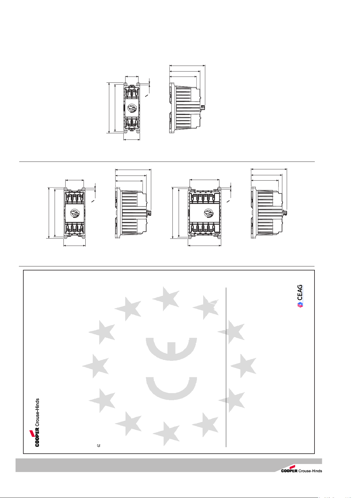
Modulés antidéflagrantes, GHG 62. .... R....
6 Montage
Avant le montage, il faut s’assurer du parfait
état des modules, en particulier de l’absence
d’avaries de transport (fissures et dommages
sur l’encapsulation résistante à la pression ou
autres endommagements des modules).
Le montage des modules peut s’effectuer au
choix pour un encliquetage sur un rail profilé
DIN ou pour le vissage sur une platine de
montage (2,5 Nm).
En cas de montage direct sur une platine de
montage, les boîtiers ne doivent reposer que
sur les points de fixation prévus et être fixés
sans gauchissement.
La vis sélectionnée doit être adaptée à
l’ouverture de fixation (voir plans cotés) et elle
ne doit pas endommager l’ouverture (utiliser
par exemple une rondelle).
Le serrage excessif des vis de fixation peut
endommager le boîtier de module.
6.1 Raccordement électriqueRaccordement électrique
Raccordement électriqueRaccordement électrique
Raccordement électrique
Le raccordement électrique de l’appareil
ne doit être effectué que par un personnel
qualifié.
Les embouts sectionnés des conducteurs
doivent être raccordés en respect des
prescriptions applicables.
Afin de maintenir l’indice de protection, ces
raccordements sont à effectuer avec la plus
grande attention.
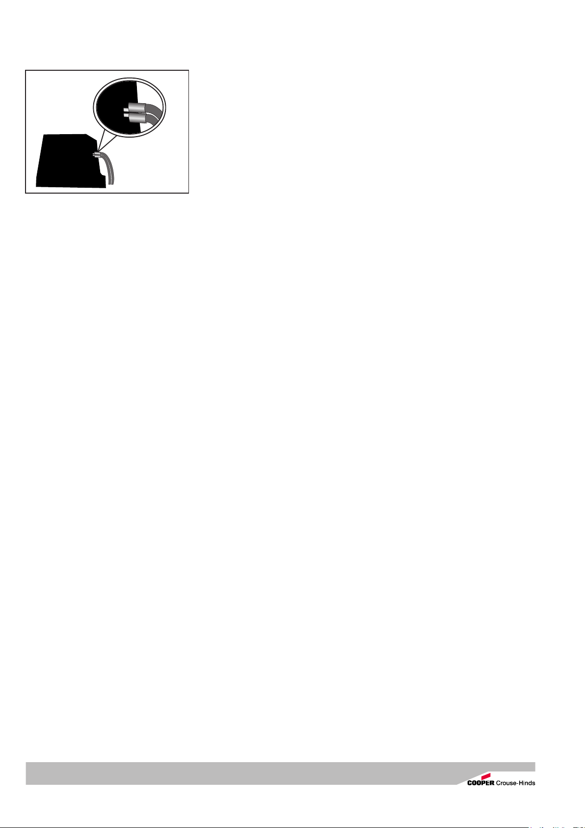
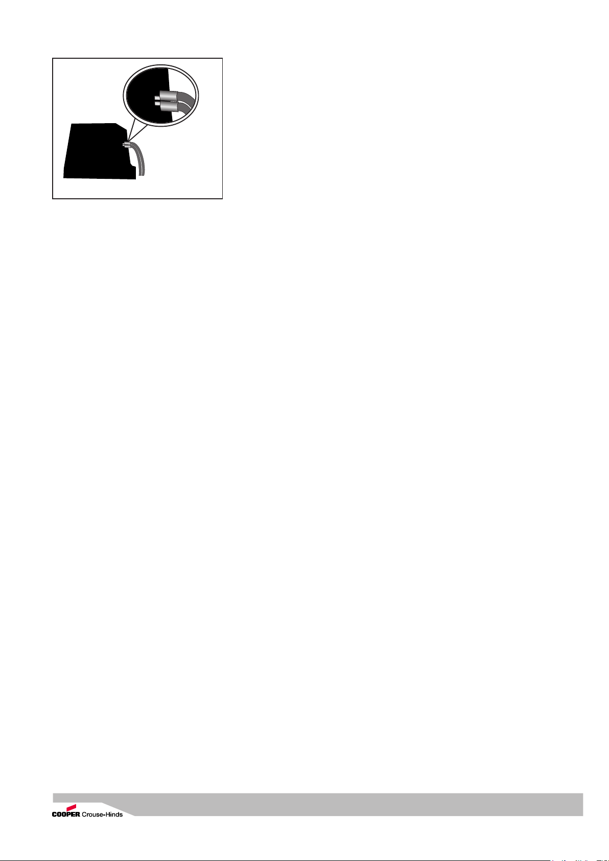
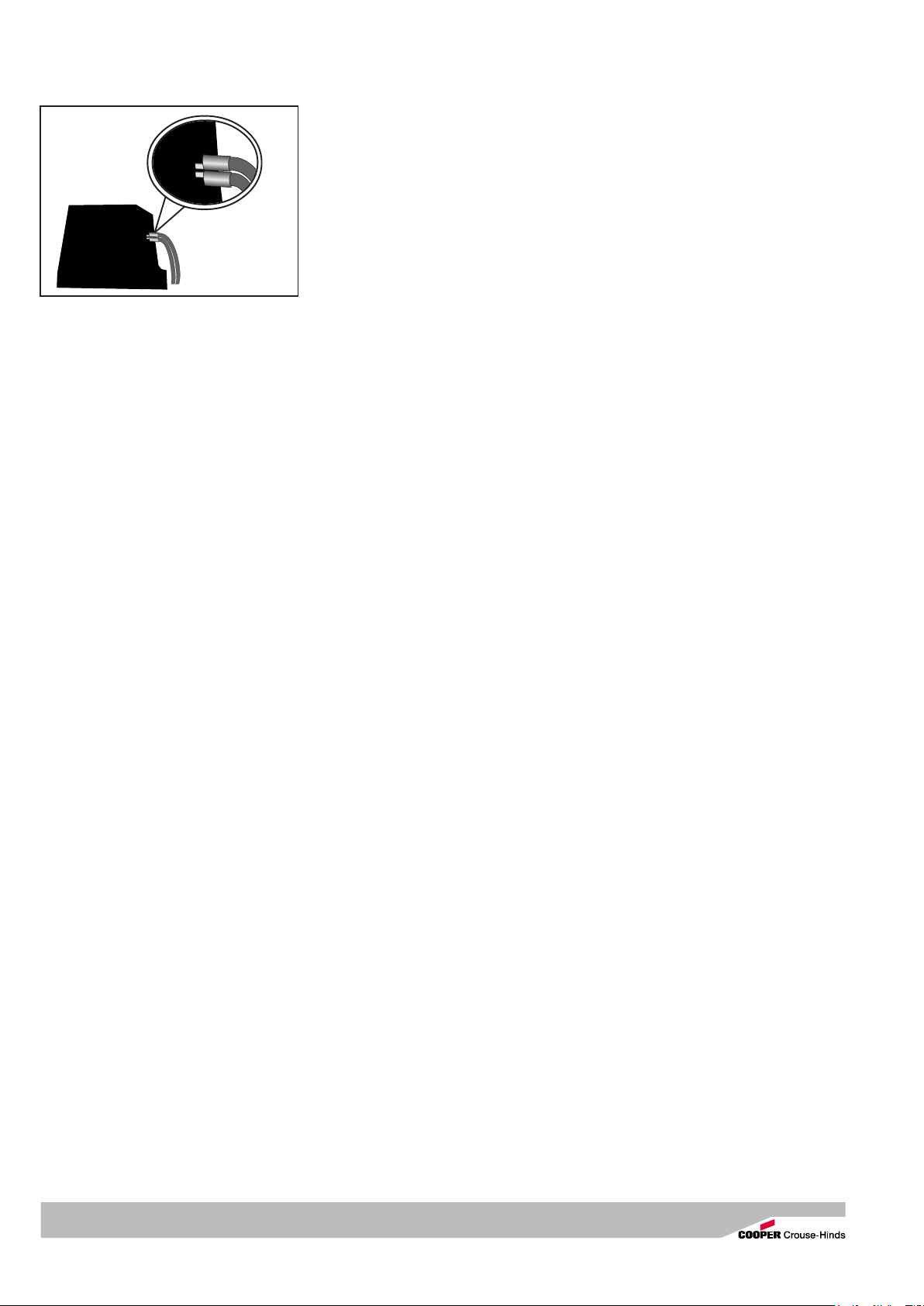
Fig. 2
correspondante les propriétés et l’utilisation
de ces modules.
Les données des points 3 et 4 doivent
être prises en compte lors de l’utilisation.
Toute utilisation autre sans accord écrit
du constructeur que celle prescrite est
interdite.
Les valeurs limites valables pour la „sécurité
intrinsèque“ doivent être respectées.
Lors de l’utilisation, les consignes du point 7
de la notice sont à respecter.
La responsabilité relative à l’utilisation
conforme et appropriée de modulés est
celle de l’utilisateur seul.
L’isolation doit s’étendre jusqu’à la borne.
Le conducteur ne doit pas être endommagé.
Les diamètres minimaux et maximaux des
conducteurs sont à respecter.
Deux conducteurs avec des cosses broches
dans un seul terminal, ont pour la connexion
à la Fig.2 montre.
Toutes les vis et/ou écrous des bornes de
connexion (y compris celles / ceux restant
inutilisés) doivent être serrés à fond.
La borne standard montée est prévue pour un
raccordement direct des conducteurs avec
des fils en cuivre.
Le schéma électrique des composants intégrés
est indiqué sur les modules, joint à l’appareil
de commande ou bien il figure dans le mode
d’emploi. Dans le cas de distributions ou
d’installations câblées, il faut respecter le
plan de connexion joint qui accompagne
l’équipement.
En cas d’utilisation de câble / presse-étoupe
multifilaire ou de câbles/presse-étoupe à
petit conducteur, les règles nationales et les
prescriptions internationales doivent être
respectées (par exemple, utilisation de
douilles pour conducteurs).
L’entretien nécessaire des intervalles sont
propre à l’utilisation et donc en fonction
des conditions de travail de fixer des
directives/normes nationales, dans une
propre responsabilité de l’opérateur.
D’entretien des si intervalles ne devaient
pas être fixés pour le test de performance
du FI-Schutzschalters, le fabricant
recommande la fonction actionne à la clé
d’essai réexaminer 2 fois par an.
Ce faisant, le disjoncteur différentiel doit
se déclencher normalement. Si ce n’est
pas le cas, la fonction de protection n’est
plus assurée et ce disjoncteur différentiel
doit être remplacé.
L’entretien nécessaire des intervalles sont
propre à l’utilisation et donc en fonction
des conditions de travail de fixer des
directives/normes nationales, dans une
propre responsabilité de l’opérateur.
Ce faisant, le disjoncteur différentiel doit
se déclencher normalement. Si ce n’est
pas le cas, la fonction de protection n’est
plus assurée et ce disjoncteur différentiel
doit être remplacé.
Dans le cadre des travaux d’entretien, ce
sont particulièrement les éléments dont
dépend l’indice de protection qui doivent être
vérifiés.
Si des travaux de remise en état sont
jugés nécessaires, on se reportera au
chapitre 8 de ce mode d’emploi.