Installation Instructions for the Sure-Lites SELDW Emergency Luminaire for Hazardous Locations
ACTIVATING TIME DELAY
The SELDW has an integrated time delay circuit that allows the
emergency lights to remain in emergency mode 15 minutes
after power is restored. Remove the jumper on the circuit board
labeled TDM/J4 to activate the time delay.
SETTING BROWN OUT CIRCUIT
Because of the universal input of the SELDW, the battery
charger will continue to function if voltage sags, even if the
normal power lights in the area fail. Selecting the appropriate
incoming voltage sets the voltage threshold for the brownout
circuit, so that the emergency lights will come on if voltage
sags. The SELDW ships with the circuit set to 120V. Determine
the incoming voltage, and select the appropriate jumper for the
brownout circuit (see Schematic).
OPERATION
The Sure-Lites Eagle Eye Self Diagnostics is continuously
monitoring your emergency light and will signal any failure
through the 3 color indicator LED.
Initial Operation
When the unit is first powered up it will go into a 24 hour fast
charge as indicated by the indicator LED pulsing green. Once
the unit has fully charged it will perform a self-calibration as
indicated by the steady green indicator LED. At this point the
unit will be float charging the battery to maintain a full charge.
Automatic Testing
The unit will perform a battery capacity, lamp/LED, and charge
circuit test every 30 days for 30 seconds. During testing the
indicator LED will change to a steady yellow. The unit will
perform a full battery capacity test for 90 minutes once per
year. During testing the indicator LED will change to a blinking
yellow.
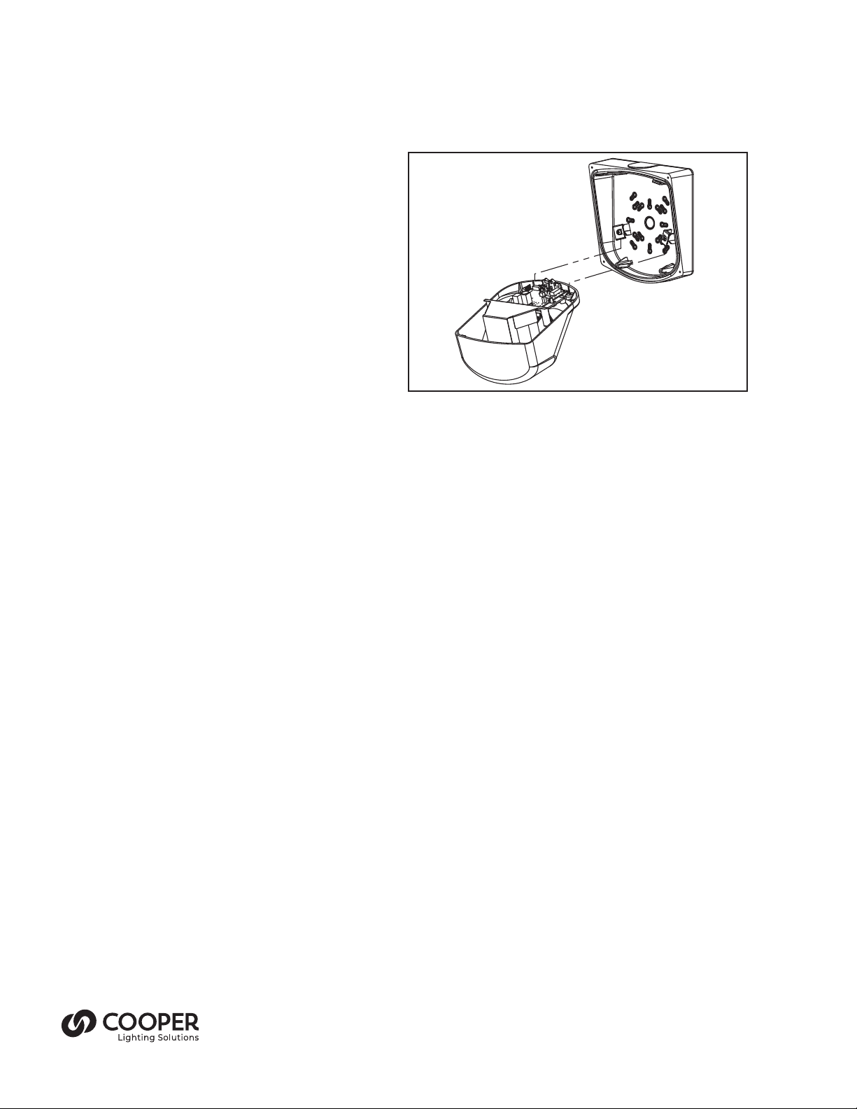
Figure 2
3. Remove the cover by removing two screws at the bottom,
and lifting the cover hooks from the slots on thebackplate.
4. Remove the conduit plug at the the appropriate location
for the mounting (left side, right side, or top or backplate).
Remove only one plug and replace with hub and conduit
for hazardous location. If additional conduit mounts are
needed, a second Myers STGK 1 hub should be ordered.
Unscrew the conduit plug from the backplate using a
5/8” or 15mm wrench Connect conduit using the ½”
liquid tight fitting provided (See Figure 3). Both the Myers
STGK 1 and HUB1 by Cooper Lighting Solutions Crouse-
Hinds are approved or hazardous location use with this
exit sign. Conduit hubs must engage at least 3 and a half
threads for supply connections.
5. Secure the emergency light to the wall using one or more
of the knockouts provided. Remove the knockouts using a
hammer and flat blade screw driver.
NOTE: When mounting the SELDW, it is necessary to consider
the weight of the emergency light, about six pounds. A
suitable anchor is recommended, or mounting directly to a
stud, for the unit itself.
NOTE: The foam gasket on the back of the SELDW is suitable
for smooth surfaces, but for rough surface mounting,
silicone caulk should be used to prevent water from
entering the emergency light.
6. Once the backplate is secured, the housing can be held in
place during installation using the EZ Hang feature. (see
Fig. 2)
7. Connect incoming ground to the green ground wire.
8. Connect the incoming wires to the SELDW’s power supply
wires using the wire nuts provided. Connect the white
wire to neutral. Connect the black wire to the hot lead.
The SELDW uses a universal input power supply that will
accept from 120-277VAC (see Schematic).
9. Connect the battery leads to the PCB (see Schematic).
10.Replace the cover assembly, and adjust the heads
as needed. Once the area is returned to a hazardous
condition, do not adjust the heads for danger of spark.
11. Replace the weather shield.To insure a water tight fit,
make sure the gasket and weather shield edge are clean
and free of debris.
12.Energize AC supply. The test button should illuminate, and
LED heads will illuminate briefly when the test button is
pushed or laser test is engaged.


