manuals.online logo
Brands
  1. Home
  2. •
  3. Brands
  4. •
  5. Samson
  6. •
  7. Valve Positioner
  8. •
  9. Samson 3730-4 User manual

Samson 3730-4 User manual

Other manuals for 3730-4

6

This manual suits for next models

1

Other Samson Valve Positioner manuals

Samson TROVIS 3730-3 Service manual

Samson

Samson TROVIS 3730-3 Service manual

Samson 3760 Service manual

Samson

Samson 3760 Service manual

Samson Type 3766 Service manual

Samson

Samson Type 3766 Service manual

Samson TROVIS 3730-3 Service manual

Samson

Samson TROVIS 3730-3 Service manual

Samson 3724 Service manual

Samson

Samson 3724 Service manual

Samson 3785 series Service manual

Samson

Samson 3785 series Service manual

Samson TROVIS 3730-3 Service manual

Samson

Samson TROVIS 3730-3 Service manual

Samson 3761 Service manual

Samson

Samson 3761 Service manual

Samson EB 8075 EN Service manual

Samson

Samson EB 8075 EN Service manual

Samson 4763 Service manual

Samson

Samson 4763 Service manual

Samson TROVIS 3730-3 User manual

Samson

Samson TROVIS 3730-3 User manual

Samson TROVIS 3730-1 Setup guide

Samson

Samson TROVIS 3730-1 Setup guide

Samson TROVIS 3730-3 User guide

Samson

Samson TROVIS 3730-3 User guide

Samson TROVIS 3793 User manual

Samson

Samson TROVIS 3793 User manual

Samson 3767 Service manual

Samson

Samson 3767 Service manual

Samson TROVIS SAFE 3731-3 Service manual

Samson

Samson TROVIS SAFE 3731-3 Service manual

Samson 3730 Series Service manual

Samson

Samson 3730 Series Service manual

Samson TROVIS 3731-3 Service manual

Samson

Samson TROVIS 3731-3 Service manual

Samson TROVIS 3793 User manual

Samson

Samson TROVIS 3793 User manual

Samson 4765 Service manual

Samson

Samson 4765 Service manual

Samson 3785 series Service manual

Samson

Samson 3785 series Service manual

Samson TROVIS 3730-3 Service manual

Samson

Samson TROVIS 3730-3 Service manual

Samson 3730-4 Instruction sheet

Samson

Samson 3730-4 Instruction sheet

Samson 373 Series User manual

Samson

Samson 373 Series User manual

Popular Valve Positioner manuals by other brands

HALDER 23111.0016 Short instruction manual

HALDER

HALDER 23111.0016 Short instruction manual

Parker 404XE Series product manual

Parker

Parker 404XE Series product manual

Ytc TMP-3000 product manual

Ytc

Ytc TMP-3000 product manual

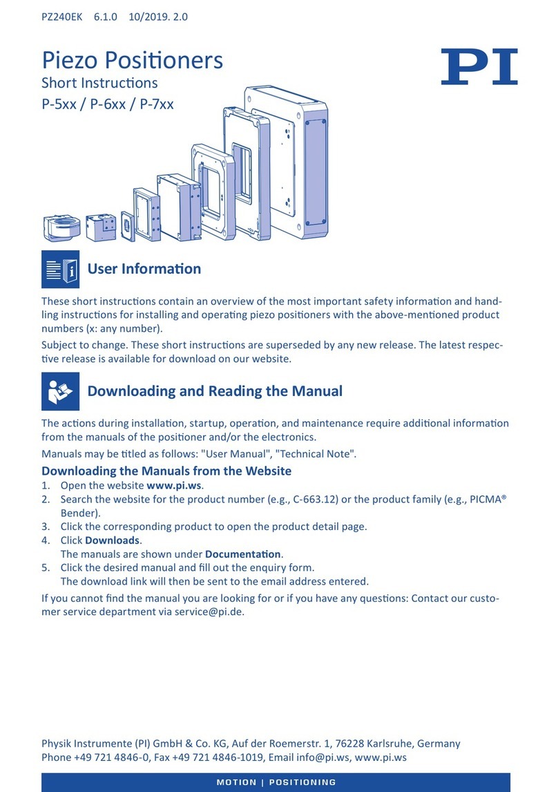
PI M-605 Series user manual

PI

PI M-605 Series user manual

Pepperl+Fuchs PXV100AS-F200-SSI-V19 manual

Pepperl+Fuchs

Pepperl+Fuchs PXV100AS-F200-SSI-V19 manual

RTK RE 3442 Series Installation and operating instructions

RTK

RTK RE 3442 Series Installation and operating instructions

CVS Controls 1200 instruction manual

CVS Controls

CVS Controls 1200 instruction manual

Westlock Quantum 2800 Installation & operating instructions

Westlock

Westlock Quantum 2800 Installation & operating instructions

ESCO Technologies ETS LINDGREN 2302-001 user manual

ESCO Technologies

ESCO Technologies ETS LINDGREN 2302-001 user manual

Parker MX80L series product manual

Parker

Parker MX80L series product manual

SMC Networks IP8000 manual

SMC Networks

SMC Networks IP8000 manual

Siemens SIPART PS2 operating instructions

Siemens

Siemens SIPART PS2 operating instructions

Burkert 8694 operating instructions

Burkert

Burkert 8694 operating instructions

iXBlue POSIDONIA II Technical description

iXBlue

iXBlue POSIDONIA II Technical description

Flowserve Logix 3200IQ Replacement instructions

Flowserve

Flowserve Logix 3200IQ Replacement instructions

Lang LHT500 Assembly instruction

Lang

Lang LHT500 Assembly instruction

Spirax Sarco SP7-21 quick start guide

Spirax Sarco

Spirax Sarco SP7-21 quick start guide

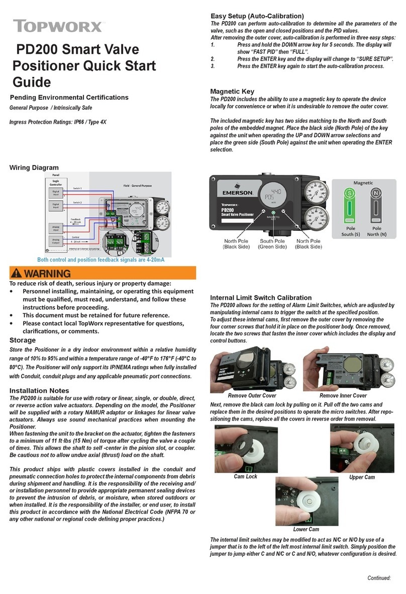
Topworx PD200 quick start guide

Topworx

Topworx PD200 quick start guide

manuals.online logo
manuals.online logoBrands
  • About & Mission
  • Contact us
  • Privacy Policy
  • Terms and Conditions

Copyright 2025 Manuals.Online. All Rights Reserved.

Die vorliegende Kurzanleitung ersetzt
nicht
die dem Gerät bei-
liegende Einbau- und Bedienungsanleitung.
Die in der Einbau- und Bedienungsanleitung enthaltenen Si-
cherheits- und Warnhinweise sind unbedingt zu beachten.
1. Montage
Direktanbau an SAMSON-Antrieb Typ 3277
Hub mm Antrieb cm2Stiftposition Hebel
7,5 120 25 M
15 240/350 35 M
15/30 700 50 M
Hinweis: Hebel M mit Abtaststift auf Stiftposition 35 mm für 15 mm Hub
ist serienmäßig montiert!
4Zur Montage des Stellungsreglers den Hebel anheben, da-
mit der Abtaststift auf dem Mitnehmer der Antriebsstange
zum Liegen kommt.
NAMUR-Anbau:
4Maximalen Hubbereich des Stellventiles (Stellung Zu bis zum
gegenüberliegenden Anschlag) durch volles Be- und Entlüf-
ten ermitteln.
4Den zum max. Hubbereich passenden Hebel sowie die
nächstgrößere Stiftposition auswählen und auf der Welle
des Stellungsreglers verschrauben.
4Hebelauswahl/Stiftabstand: siehe Tabelle auf Deckelschild
4Den NAMUR-Winkel so am Ventiljoch festschrauben, dass er
bei ca. 50 % Hubstellung mittig zum Schlitz der Mitnehmer-
platte steht.
4Stellungsregler am NAMUR-Winkel befestigen, der Ab-
taststift muss dabei im Schlitz der Mitnehmerplatte liegen.
Auf freie Hebelbeweglichkeit achten.
Anbau an Schwenkantriebe:
4Hebel MStiftposition 90°
4Ventil in Schließstellung bringen, Öffnungsrichtung bestimmen.
4Mitnehmer auf die geschlitzte Antriebswelle aufstecken und
zusammen mit Kupplungsrad verschrauben. Untere und
obere Befestigungswinkel am Antrieb montieren.
4Den Stellungsregler so auf die Winkel aufsetzen und fest-
schrauben, dass der Hebel mit seinem Abtaststift unter Be-
rücksichtigung der Öffnungsrichtung in den Schlitz des
Kupplungsrades eingreift.
Es muss in jedem Fall gewährleistet sein, dass innerhalb des
Arbeitsbereiches die mittlere Hebelstellung durchlaufen wird
(mittlere Hebelstellung = Hebel steht parallel zur Längsseite
des Stellungsreglergehäuses).
4Pneumatische Anschlüsse:
Anschlussverschraubungen nur in den jeweils montierten
Verbindungsblock, die Anschlussplatte bzw. den Manome-
terblock aus dem Zubehör einschrauben.
2. Inbetriebnahme
4Pneumatische Hilfsenergie (1,4 bis 6 bar) aufschalten.
4Elektrische Führungsgröße gemäß IEC 61158-2 einspeisen.
Sicherheitsstellung eingeben:
Schiebeschalter gemäß der Sicherheitsstellung des Stellventiles
auf AIR TO OPEN (Stelldruck öffnet) oder
AIR TO CLOSE (Stelldruck schließt) setzen.
Volumendrossel Q der Antriebsgröße anpassen:
Drossel nur bei Antrieben < 240 cm2auf
MIN SIDE bei seitlichem Anschluss oder
MIN BACK bei rückseitigem Anschluss stellen.
Achtung! Nach jeder Veränderung der Drosselstellung ist eine
Neuinitialisierung notwendig.
This Quick Guide does
not
substitute the Mounting and Oper-
ating Instructions delivered with the positioner.
The warnings and safety instructions in the Mounting and Op-
erating Instructions must be followed.
1. Mounting
Direct attachment to SAMSON Type 3277 Actuator
Travel mm Actuator cm2Pin position Lever
7.5 120 25 M
15 240/350 35 M
15/30 700 50 M
Note: Standard delivery includes lever M ready assembled with the follower
pin on 35 mm pin position for 15 mm travel!
4To mount the positioner, lift the lever so that the follower pin
rests on the follower clamp of the actuator stem.
NAMUR attachment:
4Determine the maximum travel range of the control valve
(closed position to as far it will go in the other direction) by
applying the max. supply air to the actuator and then ven-
ting the actuator completely.
4Select the lever to match the maximum travel range as well
the next largest pin position and screw onto the shaft of the
positioner.
4Lever option/pin distance: see table on cover plate.
4Screw the NAMUR bracket onto the valve yoke so that it is
aligned centrally to the slot of the follower plate when the
travel position is at approx. 50 %.
4Secure the positioner to the NAMUR bracket, making sure
that the follower pin is in the slot of the follower plate.
Make sure the lever can still move.
Attachment to rotary actuators:
4Lever MPin position 90°
4Put the valve into the closed position, determine the opening
direction.
4Place the follower plate on the slotted actuator shaft and
fasten it to the coupling wheel. Attach the upper and lower
brackets to the actuator.
4Place the positioner on the brackets and screw tight, making
sure that the lever with its follower pin engages the slot of
the coupling wheel, while taking into account the opening
direction.
It is important to make sure that the lever's mid position corre-
sponds to the mid travel of the valve (lever's mid position =
lever is parallel to the long side of the positioner housing).
4Pneumatic connections:
Screw the threaded connections only into the attached mount-
ing block, connecting plate or pressure gauge block from the
accessories.
2. Start-up
4Connect pneumatic supply air (1.4 to 6 bar).
4Apply electrical reference variable according to
IEC 61158-2.
Set the fail-safe position:
Set the slider switch to match fail-safe position of the valve:
AIR TO OPEN (signal pressure opens the valve) or
AIR TO CLOSE (signal pressure closes the valve).
Adapt the volume restriction Q to the actuator size:
Only set the restriction for actuators < 240 cm2to
MIN SIDE for connection at the side or
MIN BACK for connection at the back.
Caution! After each change of the restriction position, a new
initialization is necessary.
Elektropneumatischer Stellungsregler Typ 3730-4/-5 Electropneumatic Positioner Type 3730-4/-5
Changing the reading direction of the display (if necessary)
Turn →Code
2
,↵, turn →Display ok, ↵
Operation
Selecting the parameters or values
Each parameter has a code number which is shown in the dis-
play. Use the rotary pushbutton to select. Turn the button to
select parameters or values and then push ↵to confirm. Press
ESC
to prevent an entered value from being accepted.
Enabling parameters
Parameters that have a code marked with * can only be chan-
ged when they are enabled beforehand using Code
3
.
The configuration mode is shown in the display with the
symbol.
See cover plate for a description of the menu codes.
3. Initialization
Important: If the positioner is mounted onto another actuator or
the mounting situation is changed, reset the positioner to its de-
fault setting (Code 36) prior to each initialization
Turn →Code
3
,↵, turn →
ON
,↵
Turn →Code
36
,↵, select
RUN
,↵
Warning! During initialization, the valve runs through its whole
range of travel/rotation.
3.1 Simplest method (MAX) [default setting]
Mount and start up the positioner and press INIT key!
READY!
The positioner adapts itself automatically to the maxi-
mum travel/rotational angle range of the control valve.
3.2 Precise method (NOM)
Positioner adapts itself precisely to the rated travel/rotational
angle of the control valve!
Mount and start up the positioner, then proceed as follows:
Turn →Code
3
,↵, turn →
ON
,↵
Turn →Code
4
,↵, select pin position, ↵
Turn →Code
5
,↵, enter rated travel/angle, ↵
Turn →Code
6
,↵, select
NOM
,↵
Press INIT key!
3.3 Manual method (MAN)
Initialization mode same as
NOM
, but for start-up of control
valves with unknown rated range.
The final position of travel/rotational angle (valve open) is en-
tered manually.
Mount and start up the positioner, then proceed as follows:
Turn →Code
0
,↵, turn →select
MAN
,↵
Turn →Code
1
,↵, turn →valve
open
position, ↵
Turn →Code
3
,↵, turn →
ON
,↵
Turn →Code
6
,↵, select
MAN
,↵
Press INIT key!
Note: After applying the electrical reference variable, the posi-
tioner is in the last used operating mode. Code
0
appears in
the display. If the positioner has not yet been initialized, the
icon blinks.
For detailed information on mounting and operation, refer to:
EB 8384-4 EN for Type 3730-4
EB 8384-5 EN for Type 3730-5
Anzeige der Leserichtung anpassen (wenn notwendig)
- drehen →Code
2
,↵, - drehen →Anzeige ok, ↵
Bedienung
Auswahl der Parameter bzw. Werte
Jedem Parameter ist eine Codezahl zugeordnet, die im Display
angezeigt wird. Die Auswahl wird mit dem Dreh-/Druckknopf
vorgenommen. Durch Drehen des Dreh-/Druckknopfes wer-
den Parameter bzw. deren Werte ausgewählt und durch an-
schließendes Drücken ↵aktiviert.
Bei
ESC
erfolgt ein Abbruch der Eingabe ohne Wertübernahme.
Freigabe von Parametern
Parameter die zu einem mit * gekennzeichneten Code gehören,
können nur dann verändert werden, wenn vorher über Code
3
die Freigabe erfolgt ist.
Der Konfigurationsmodus wird mit dem -Symbol angezeigt.
Zur Erklärung der Menücodes siehe Deckelschild.
3. Initialisierung
Wichtig: Wird der Stellungsregler an einen anderen Antrieb an-
gebaut oder wird die Einbausituation verändert, ist der Stellungs-
regler vor einer Neuinitialisierung auf die Grundeinstellung mit
Standardwerten (Code 36) zurückzusetzen.
- drehen →Code
3
,↵, - drehen →
ON
,↵
- drehen →Code
36
,↵,
RUN
wählen, ↵
Warnung! Während der Initialisierung durchfährt das Ventil
den gesamten Hub-/Winkelbereich.
3.1 Einfachste Methode
(MAX)
[Defaultwert]
Montieren, Inbetriebnehmen und INIT-Taste drücken!
FERTIG!
Der Stellungsregler adaptiert sich vollautomatisch auf
den maximalen Hub-/Drehwinkelbereich des Stell-
ventiles.
3.2 Exakte Methode (NOM)
Stellungsregler adaptiert sich exakt auf den Nennhub/winkel
des Stellventiles!
Montieren, Inbetriebnehmen, dann
- drehen →Code
3
,↵, - drehen →
ON
,↵
- drehen →Code
4
,↵, Stiftposition wählen, ↵
- drehen →Code
5
,↵, Nennhub/winkel eingeben, ↵
- drehen →Code
6
,↵,
NOM
wählen, ↵
Abschließend INIT-Taste drücken!
3.3 Manuelle Methode (MAN)
Initialisierungsmodus wie NOM, doch zur Inbetriebnahme von
Stellventilen mit unbekanntem Nennbereich. Die Hub/Dreh-
winkel-Endstellung (Ventil Auf) wird von Hand vorgegeben.
Montieren, Inbetriebnehmen, dann
- drehen →Code
0
,↵, - drehen →
MAN
wählen, ↵
- drehen →Code
1
,↵, - drehen →
Auf
-Stellung Ventil, ↵
- drehen →Code
3
,↵, - drehen →
ON
,↵
- drehen →Code
6
,↵,
MAN
wählen, ↵
Abschließend INIT-Taste drücken!
Hinweis: Nach Anlegen der elektrischen Führungsgröße befin-
det sich das Gerät in der zuletzt benutzten Betriebsart, im Dis-
play erscheint Code
0
. Wurde der Stellungsregler noch nicht
initialisiert, blinkt das Handsymbol .
Einzelheiten sind den Einbau- und Bedienungsanleitungen zu entneh-
men: Typ 3730-4 siehe EB 8384-4
Typ 3730-5 siehe EB 8384-5
Edition July 2008 Quick guide KA 8384-4 EN Ausgabe Juli 2008 Kurzanleitung KA 8384-4