Issue
N
C.S.
04.03.20 Trading Estate Farnham Surrey England Doc. No. TD 120
Page 9 of 25
Title : Installation, Operation & Maintenance Instructions – IS Digital EL Positioner
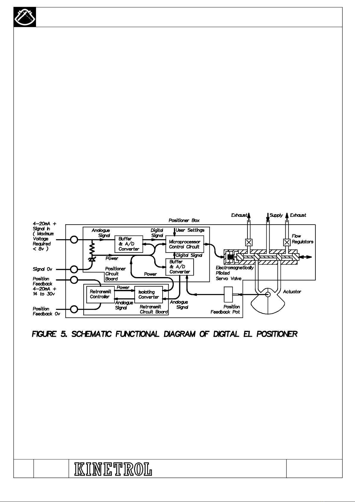
5.SET UP (Continued)
5.7 Proportional Gain and Damping Settings (for Smoothness and Sensitivity) – continued
The positioner is active while adjusting the PGAIN setting, and continues to follow the input signal. This gives the opportunity to
change the input signal in a manner typical of the application, and to observe qualitatively the response of the positioner, and
how it has been affected by changing the PGAIN setting, so as to optimise the response. Pressing the UP button maximises the
sensitivity and accuracy, at the cost of increased jerkiness of response when the signal is ramped smoothly, and if you go too far
this increases the proportional gain so much that the positioner becomes unstable and hunts around the position set by the
signal. Pressing the DOWN button maximises smoothness during ramping of the signal, at the cost of losing rapidity of response
to small changes in signal. When the right setting has been found, press the SET button again to leave Adjust Mode – the PGAIN
LED will now light continuously.
The DAMP (damping) parameter should be set after the PGAIN has been optimised. In Setup Mode select the DAMP parameter
(second up from PGAIN) by pressing the UP button until the DAMP LED lights continuously. Press the SET button to select
Adjust Mode, and the DAMP LED will blink. Damping can be increased and decreased by pressing the UP or DOWN buttons.
There are twenty nine damping settings which can be selected, the setting altering by a factor of 1.1 each time the UP or DOWN
pushbutton is pressed. The default setting lies in the middle of the range, giving fourteen settings above and fourteen below. Any
button presses beyond the last (fourteenth) setting will have no effect.
Note: As soon as the UP or DOWN button is pressed, the new DAMP value is stored in non-volatile memory, and is retained
even if the positioner is de-energised before leaving Adjust and Setup Modes.
The positioner is active while adjusting the DAMP setting, and continues to follow the input signal. This allows the signal to be
waggled to optimise the response while still adjusting the DAMP setting. Try stepping the signal suddenly so that the positioner
approaches setpoint at full speed having travelled 45 degrees or more, and adjust the DAMP setting to just avoid overshoot here.
Try this travelling up and downscale. When the right setting has been found, press the SET button again to leave Adjust Mode –
the DAMP LED will now light continuously.
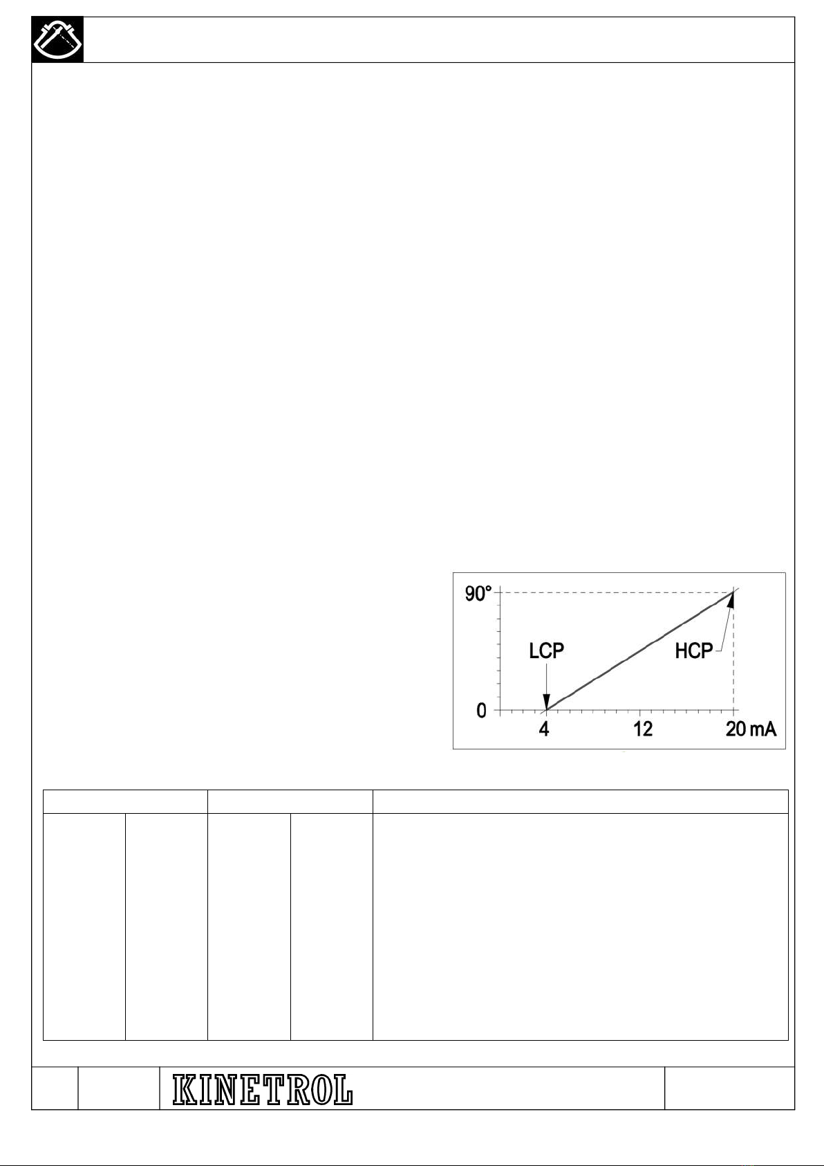
5.8 Low Current Point and High Current Point Settings. (Replaces Zero and Span Adjustment).
The positioner characteristic can be accurately calibrated by setting
two points, the Low Current Point (LCP) and the High Current Point
(HCP). Each point is defined by a position and an input current.
These points can lie anywhere in the range of travel of the actuator,
and in the input signal range of 4 to 20 mA. The only other
restriction is that the input current at the HCP must exceed the input
current at the LCP by at least 5mA. To obtain the best accuracy, it is
necessary to select the two points as far apart as possible. In both
linear and non-linear operation this allows forward acting, reverse
acting, and forward or reverse acting split range characteristics to
be implemented. Table 1 below shows some illustrative examples.
Figure 7. Illustration of LCP and HCP
Low Current Point High Current Point Description
4 0 20 90 Forward Acting, 100% range
4 90 20 0 Reverse Acting, 100% range
4 0 12 90 Split Range Forward Acting, 50% bottom range
4 90 12 0 Split Range Reverse Acting, 50% bottom range
12 0 20 90 Split Range Forward Acting, 50% top range
12 90 20 0 Split Range Reverse Acting, 50% top range
4 0 20 45 Forward Acting, 200% range
4 45 20 0 Reverse Acting, 200% range
Table 1. Various Sets of LCP and HCP Settings
N – AR7059 / M – AR6971 / L - AR6419 / K - AR6347 / J-AR6096 / H – AR 6082 / G – AR 5487 / F – AR 5608 / E - AR 5293