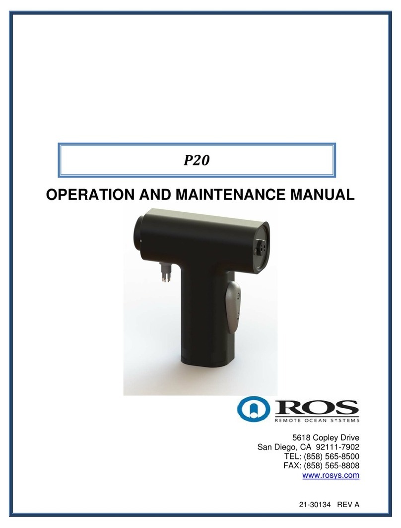
Ros P20 AC User manual

21-30265 REV A
OPERATION AND MAINTENANCE MANUAL
5618 Copley Drive
San Diego, CA 92111-7902
TEL: (858) 565-8500
FAX: (858) 565-8808
www.rosys.com
P20 AC

21-30265 REV AII
TABLE OF CONTENTS
WARRANTY ..................................................................................................................III
CUSTOMER ASSISTANCE...........................................................................................IV
CHANGE RECORD........................................................................................................V
1WARNINGS.............................................................................................................1
2DESCRIPTION.........................................................................................................1
3PRODUCT SPECIFICATIONS ................................................................................2
4INSTALLATION/ GENERAL FUNCTIONALITY......................................................3
5CONNECTOR WIRING/CONFIGURATIONS..........................................................4
6ROUTINE MAINTENANCE .....................................................................................4
7TROUBLESHOOTING.............................................................................................4

21-30265 REV AIII
WARRANTY
ROS, Inc. (hereinafter called "ROS") warrants its products as stated below subject to the
conditions specified.
ROS warrants its products, when operated under normal conditions, to be free from defects in
material or workmanship for a period of one year from the date of purchase provided that
inspection by ROS discloses that such defects developed under normal and proper use. ROS
products repaired or replaced pursuant to this warranty shall be warranted for the unexpired
portion of the warranty applying to the original product. The liability of ROS under this warranty
shall exist subject to the following conditions:
(a) Purchaser properly notifies ROS of such defects and the defective product is
returned to ROS, transportation charges paid by Purchaser.
(b) ROS shall be released from all obligations under its warranty in the event repairs
or modifications are made by persons not authorized by ROS.
(c) Representations and warranties made by any person, including distributors and
representatives of ROS, which are inconsistent or conflict with the terms of this
warranty, shall not be binding upon ROS unless reduced to writing and approved
by an officer of ROS. ROS shall in no event be liable for other direct, special,
incidental, consequential, indirect or penal damages.
(d) The laws of the State of California shall govern this warranty.
In the event the defect is determined to be within the terms of this warranty then ROS agrees to
repair and/or replace (at ROS' discretion) the product or defective portion at no charge to the
Purchaser. This warranty does not apply to expendable items or to normal wear-and-tear, and
is conditional upon performance of normal preventative maintenance procedures.
Our commitment to quality and customer service directs us to constantly strive to improve our
products. The materials and specifications presented in our manuals and data sheets are
correct and accurate to the best of our knowledge, and are presented in good faith. However,
the information is not guaranteed and is subject to change without notice.
LIMITATIONS OF REMEDIES
Purchaser assumes all risk and liability for results obtained in any installation, operation, or use
of the product. Purchaser’s sole remedy for any breach of warranty by vendor shall be limited to
the “express remedies” set forth above. Otherwise, in no event shall vendor, its agents, or
employees be liable to the original purchaser or any third party for any consequential or
incidental damages or expenses of any nature arising directly out of or in connection with the
use of vendor projects, even if vendor has been advised of the possibility of such damages or
expenses. In any event, unless otherwise contrary to state law, vendor liability under this
limited warranty shall not exceed the purchase price of the product.

21-30265 REV AIV
CUSTOMER ASSISTANCE
ROS, Inc. uses a worldwide network of stocking distributors and representatives who
are familiar with our products and are able to provide assistance during installation
and/or operation of these products.
If you have any questions or problems with this product that are not covered by this
manual or instruction, please contact our agent in your area, or contact us directly by
phone or FAX or e-mail.
TEL: (001) 858-565-8500
FAX: (001) 858-565-8808
Web Site: www.rosys.com

21-30265 REV AV
CHANGE RECORD
REV DESCRIPTION DATE
A PRODUCTION RELEASE (EC-02661) 27MAR17

21-30265 REV A1
1 WARNINGS
WARNING: Assembly, disassembly, connecting cables, or
disconnection of cables, must only occur when the P20 is
disconnected from the power source.
•Be careful when handling the positioner and/or cables due to exposed male pins
on the connectors. The pins can be damaged if they are bumped excessively.
Any damage may result in difficulty when connecting cables or possible flooding
for those connections that are underwater.
•When handling the cables, do not pull or tug on the cables more than necessary.
Connector damage may result.
2 DESCRIPTION
The model P20 Pan and Tilt is designed to remotely orient underwater or in-air video
and photographic cameras, lights, acoustic equipment, and other instrumentation. It is
designed to handle moderately heavy loads, and provides an output torque of 10 foot
pounds on each axis.
The housing, end plates, and all machined internal components of the P20 are made of
6061-T6 aluminum, which is hard anodized for corrosion protection. Other external
hardware such as screws and retaining rings are made of stainless steel. An all
titanium version is also avaliable
The drive train for each axis of the pan and tilt uses a reversible stepper motor coupled
to low backlash harmonic gearing. The output gear of the harmonic reducer is bolted
directly to the output shaft. The output shafts are each supported by two heavy-duty
ball bearings to withstand heavy side and end loads. The basic design of the drive train
is very compact, and it offers high reliability and minimum backlash.
If the P20 is oil-filled, it is pressure compensated by use of a Bellofram seal. This
provides a slight internal pressure to minimize shaft seal drag and potential leakage
problems due to hydrostatic pressure. The oil also provides continual lubrication and
cooling to the internal components.
The P20 is equipped with internal limit switches and precision feedback potentiometers
on both axes. These potentiometers sense the pan and tilt orientation angles for
display at the surface control station.

21-30265 REV A2
3 PRODUCT SPECIFICATIONS
Mechanical
Housing Material (optional) Hard Anodized 6061 AL (6AL-4V TI)
Dimensions Air: 8.1” L x 10.4” H x 3” D
Oil: 9.8” L x 10.4” H x 3” D
Mounting Options 2X ¼-20 Mounting Bolts on each axis
Optional Mounting Plate and Yoke
available
Weight in Air Air: 10.0Lb (4.5Kg)
Oil: 11.4Lb (5.2Kg)
Weight in Salt Water Air: 6.7Lb (3.0Kg)
Oil: 8.4Lb (3.7Kg)
Rotation Speed 5°/sec (both axes)
Rotation Limit 360°
Torque 10Ft-Lb
Max Mechanical Backlash ±50 arc minutes
Resolution ±30 arc minutes
Compensator Fluid Shell Tellus 10 or eq.
Environmental
Depth Rating Air: 100ft (30.5m)
Oil: 20000ft (6000m)
Min/Max Operating Temperature 0°C to 50°C
Storage Temperature -20°C to 60°C
Electrical
Max Power Draw 0.14A
Input Voltage 120 VAC
Control System Analog w/optional ROS controller(s)
available

21-30265 REV A3
4 INSTALLATION/ GENERAL FUNCTIONALITY
Your new positioner is intended for years of service free use. The positioner is not
intended to be serviced or troubleshot for major issues in the field, a troubleshooting
guide for minor issues is provided in Section 8. Please contact your sales representative
for any issues with your new positioner.
To install your new positioner, use the bolt pattern provided on each output shaft or an
available ROS mounting bracket. Note that your connector configuration will have a
specific wiring configuration. The wiring for your positioner will be designated on the
supplied test certification, but the standard wiring configuration can be found in Section
7.
Figure 1: Output Shaft Bolt Pattern

21-30265 REV A4
5 CONNECTOR WIRING
Standard configuration for the P20 is as follows:
Example:
-01 MCBH-6-MP
SS SUBCONN
PIN NUMBER FUNCTION
1 120/220 VAC RETURN
2 TILTCCW
3 TILTCW
4 PANCW
5 PANCCW
6 GROUND
Note: If a connector has more pins than is listed in the table above, all other pins that are not listed are not
connected.
6 ROUTINE MAINTENANCE
The P20 is intended to be maintenance free. Be sure to clean your positioner with fresh
water after each deployment. A visual inspection is always helpful in assessing the
integrity of the positioner. In the event the positioner stops working, please contact ROS
customer service. For troubleshooting see Section 7.
7 TROUBLESHOOTING
Problem Typical Causes Action
Product won’t power on Not connected properly Check cables and power
supply
Check wiring
Verify proper input power
Communication issues Incomplete connection or
pinout compatibility issue Verify pinout compatibility
Product is leaking oil Seal damage Return to ROS for repair
Table of contents
Other Ros Valve Positioner manuals
Popular Valve Positioner manuals by other brands

Siemens
Siemens SIPART PS2 operating instructions

ABB
ABB TZIDC manual

Festo
Festo CMSX C-U-F1 Series Translation of the original instructions

Siemens
Siemens SIPART PS2 Compact operating instructions

Bifold Orange
Bifold Orange EX200 Operation, installation, and maintenance manual

Siemens
Siemens SIPART PS2 Compact operating instructions

Heimeier
Heimeier Thermolux K Consumer information

Samson
Samson 3730 Series Mounting and operating instructions

Samson
Samson Type 3766 Mounting and operating instructions

GEM
GEM 1434 mPos Installation, operating and maintenance instructions

Baker Hughes
Baker Hughes Masoneilan SVI II AP instruction manual

Baileigh Industrial
Baileigh Industrial RWP-55-1.0 Operator's manual