CEAG Notlichtsysteme GmbH 2
Montage- und Betriebsanleitung
Einzelbatterienotleuchten Alu-Klick
71811...71821 (CG Line)
Inhaltsverzeichnis / TInhaltsverzeichnis / T
Inhaltsverzeichnis / TInhaltsverzeichnis / T
Inhaltsverzeichnis / Table of contentsable of contents
able of contentsable of contents
able of contents
11
11
1Aufbau der Leuchte / Construction of the luminaireAufbau der Leuchte / Construction of the luminaire
Aufbau der Leuchte / Construction of the luminaireAufbau der Leuchte / Construction of the luminaire
Aufbau der Leuchte / Construction of the luminaire ................................
................................
................ 33
33
3
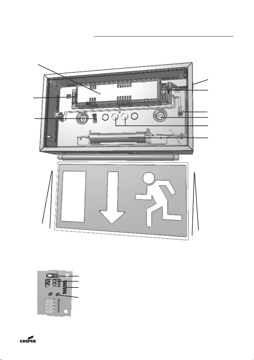
1.1 SL/RZ 71811 (CG Line) ..................................................................................... 3
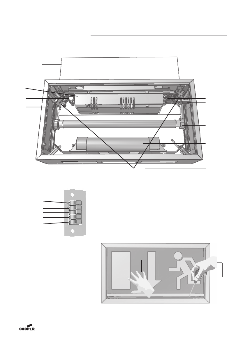
1.2 RZ 71821 (CG Line) .......................................................................................... 4
22
22
2Maßbilder / Dimensional DrawingsMaßbilder / Dimensional Drawings
Maßbilder / Dimensional DrawingsMaßbilder / Dimensional Drawings
Maßbilder / Dimensional Drawings ..........................................................................................
..........................................................................................
............................................. 55
55
5
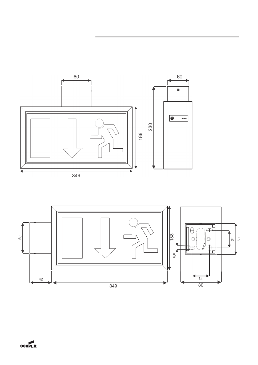
2.1 71811 (CG Line) Decken,- oder Wandmontage /
Ceiling or wall mounting ................................................................................... 5
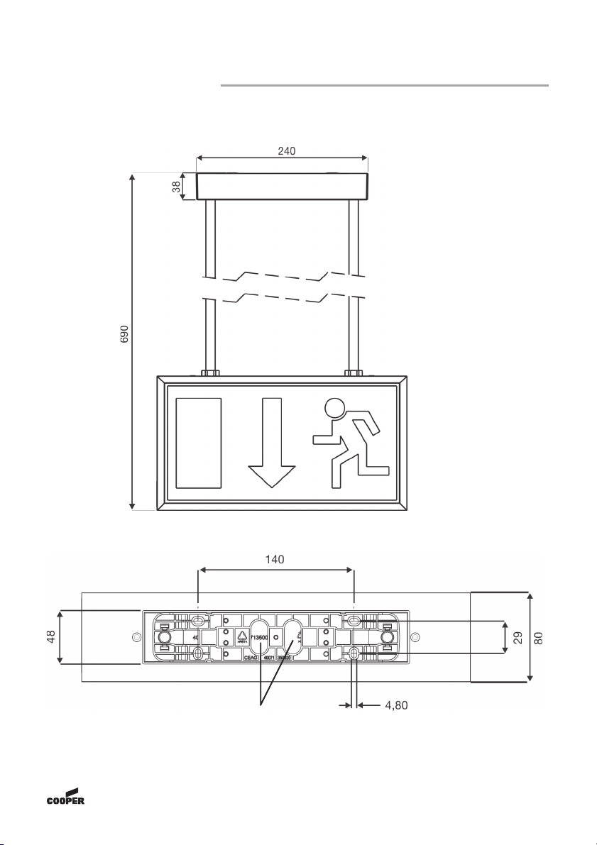
2.2 71821 (CG Line) Deckenmontage / Ceiling mounting ...................................... 6
2.3 71821 (CG Line) Wandmontage / Wall mounting ............................................. 6
2.4 Pendel Set 0,5m / Pendulum Set 0,5m für / for 71821 (CG ...............................
Line) .................................................................................................................. 7
33
33
3SicherheitshinweiseSicherheitshinweise
SicherheitshinweiseSicherheitshinweise
Sicherheitshinweise ..............................................................................................................................................
..............................................................................................................................................
....................................................................... 99
99
9
44
44
4NormenkonformitätNormenkonformität
NormenkonformitätNormenkonformität
Normenkonformität ..................................................................................................................................................
..................................................................................................................................................
......................................................................... 88
88
8
55
55
5TT
TT
Technische Datenechnische Daten
echnische Datenechnische Daten
echnische Daten ......................................................................................................................................................
......................................................................................................................................................
........................................................................... 88
88
8
5.1 Verwendungsbereich / Kurzbeschreibung ........................................................ 8
66
66
6Installation / InbetriebnahmeInstallation / Inbetriebnahme
Installation / InbetriebnahmeInstallation / Inbetriebnahme
Installation / Inbetriebnahme ..............................................................................................................
..............................................................................................................
....................................................... 99
99
9
6.1 Montage ............................................................................................................ 9
6.2 Überwachungseinrichtung CG Line ................................................................. 9
Autarker Betrieb ............................................................................................................. 10
6.3 Zubehör ........................................................................................................... 10
77
77
7Wartung / InstandhaltungWartung / Instandhaltung
Wartung / InstandhaltungWartung / Instandhaltung
Wartung / Instandhaltung ........................................................................................................................
........................................................................................................................
............................................................ 1010
1010
10
88
88
8Entsorgung / RecyclingEntsorgung / Recycling
Entsorgung / RecyclingEntsorgung / Recycling
Entsorgung / Recycling ..............................................................................................................................
..............................................................................................................................
............................................................... 1010
1010
10
33
33
3Safety instructionsSafety instructions
Safety instructionsSafety instructions
Safety instructions ..............................................................................................................................................
..............................................................................................................................................
....................................................................... 1212
1212
12
44
44
4Conformity with standardsConformity with standards
Conformity with standardsConformity with standards
Conformity with standards ..................................................................................................................
..................................................................................................................
......................................................... 1212
1212
12
55
55
5TT
TT
Technical dataechnical data
echnical dataechnical data
echnical data ............................................................................................................................................................
............................................................................................................................................................
.............................................................................. 1212
1212
12
5.1 Brief description / Scope of application .......................................................... 12
66
66
6InstallationInstallation
InstallationInstallation
Installation..........................................................................................................................................................................
..........................................................................................................................................................................
..................................................................................... 1313
1313
13
6.1 Mounting ........................................................................................................ 13
6.2 CG Line Monitoring Device ............................................................................. 13
6.3 Mounting accessories ..................................................................................... 14
77
77
7ServicingServicing
ServicingServicing
Servicing ................................................................................................................................................................................
................................................................................................................................................................................
........................................................................................ 1414
1414
14
88
88
8RecyclingRecycling
RecyclingRecycling
Recycling ..............................................................................................................................................................................
..............................................................................................................................................................................
....................................................................................... 1414
1414
14