manuals.online logo
Brands
  1. Home
  2. •
  3. Brands
  4. •
  5. COPLATE
  6. •
  7. Bicycle Accessories
  8. •
  9. COPLATE B-THiA1 User manual

COPLATE B-THiA1 User manual

1www.bikeacces.com
Handleiding CBTHiA1
Manual CBTHiA1
Model: COPLATE®+ set/kit B-THiA1
Te gebruiken in combinatie met de Thinkrider A1 etstrainer.
To be used in combination with the Thinkrider A1 cycle trainer.
Benodigd gereedschap
Tools required
De informatie en gegevens in deze handleiding kan zonder voorafgaande kennisgeving worden gewijzigd.
Geen enkel deel van deze handleiding mag worden verveelvoudigd in enige vorm of op enige wijze zonder de schriftelijke toestemming van de BIKEACCES.
The information and data given in this user manual can be changed without prior notice.
No part of this manual may be reproduced in any form or by any means without the written permission of the BIKEACCES
SW8
2www.bikeacces.com
18-10-2019
90°
ventielgat
valve hole
2
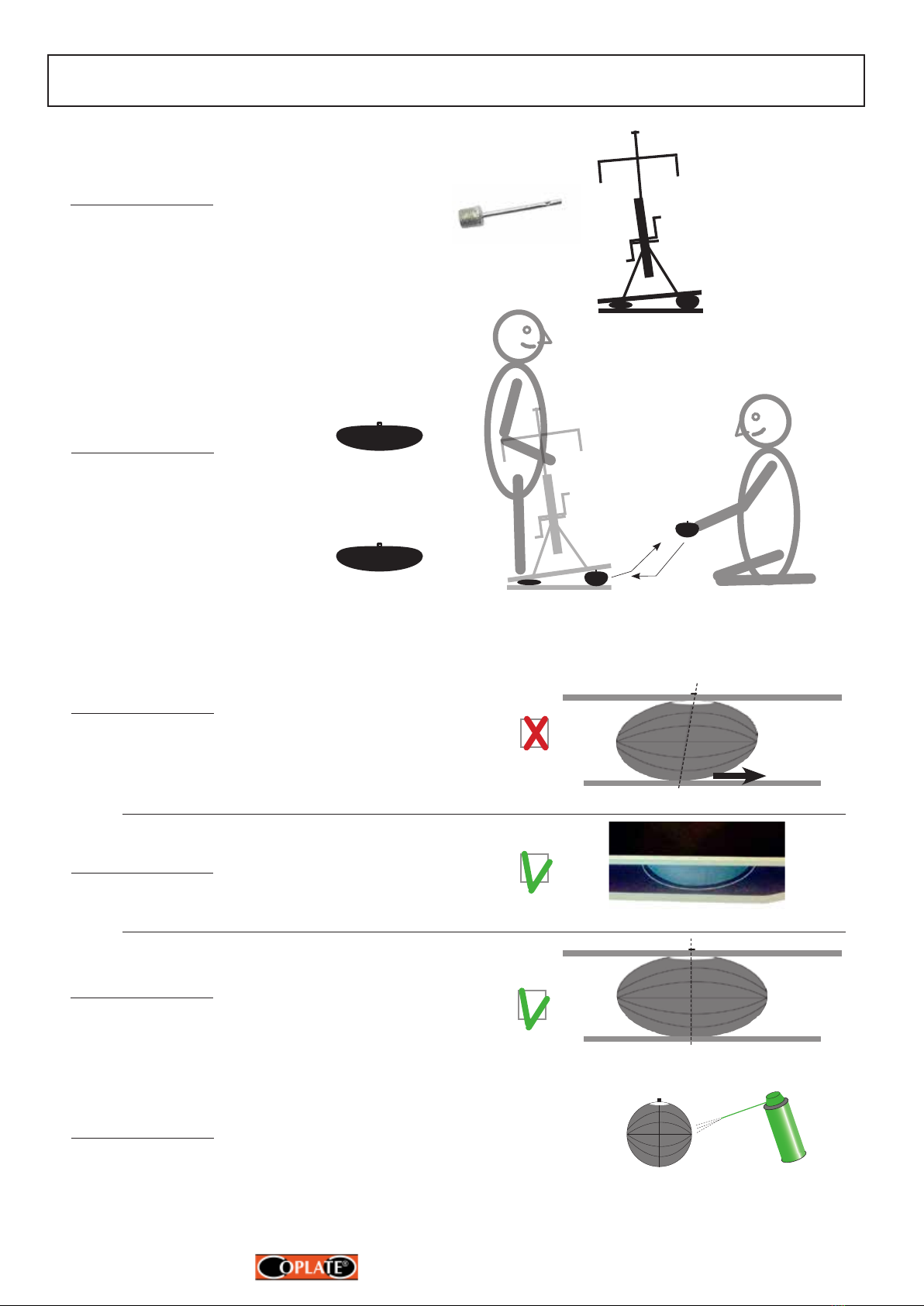
Spuit wat smeermiddel op de naald en steek
deze in het ventielgat (herhaal dit indien nodig).
Spray some lubricant on the needle and insert it
in the valve hole (repeat if necessary).
Siliconen,
PTFE (Teon)
of/or WD40 1NOOIT GEBRUIKEN!
NEVER USE!
3
Lees a.u.b. eerst de onderstaande
instructies voordat U begint!
Gebruik en op druk zetten van de luchtvering.
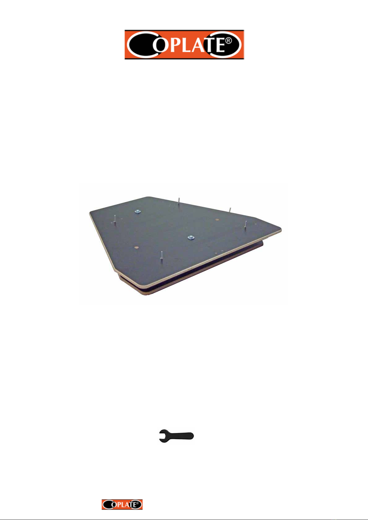
• Onder de COPLATE wordt een trainermat (b.v. Tacx T2910), rubber
mat of vloerbedekking sterk aanbevolen, dit om beschadiging van de
vloer te voorkomen.
• Schuif de pompnaald of manometer voorzichtig onder een hoek van
90° volledig in de ventielopening. (zie onder 1). Als U tijdens het
insteken van de naald veel weerstand ondervindt, smeer dan eerst de
naald van de pomp met enkele druppels siliconen spray/olie, PTFE
(Teon) olie, WD40 olie of glycerine, zodat er bijna geen weerstand is
tijdens het insteken van de naald. (zie onder 2).
• Geen olie in het ventielgat spuiten!
• Zonder smering kan het ventiel van de luchtvering losraken, bescha-
digd worden en lekkage optreden.
• Als de naald tot het einde is ingebracht zal het oppompen en aaten
van de druk gemakkelijk gaan.
• De druk alleen verhogen met de bijgeleverde handpomp. Nooit een
elektrische etspomp of compressor gebruiken waardoor de luchtve-
ring zou kunnen exploderen! zie onder 3
• Aanbevolen druk ligt tussen de 0,1 bar (1,5 psi) en 0,2 bar (3 psi).
• De maximum druk is 0,2 bar. (3 psi), barstdruk 0,8 bar (11,5 psi)
• Breng de kantelplaat in horizontale positie met behulp van de water-
pas door de druk in de twee luchtveringen te verhogen of te verlagen
en met behulp van de bijgeleverde manometer (ref.14029)
• Niet op de bovenplaat van de plaat gaan staan.
• Gebruik bij voorkeur de opstap ref. CP-OS om op en af te stappen.
• Door de druk van de luchtvering kunnen de boven- en onderplaat
enigzins doorbuigen, dit is normaal. Indien er lange tijd geen gebruik
wordt gemaakt van de plaat wordt aanbevolen de druk af te laten tot
+/- 0,05 bar (0,7 psi).
• Neem plaats op de etstrainer en kijk naar beneden naar de trapas.
Als u naar links moet hangen om de ets in balans te krijgen verhoog
dan de druk met enkele pompslagen aan de rechter zijde of omge-
keerd. Van bovenaf gezien loopt de bovenbuis dan door het midden
van de trapas.
• Maximum gewicht gebruiker: 120 kg.
• Onderhoud: de luchtvering tussen de platen niet blootstellen aan
direct zonlicht en maandelijks insmeren met glycerine, WD40 of
siliconen(spray) om de levensduur te verlengen.
Please read the instructions below
before you start!
Use and inating air suspension.
• Under the COPLATE a trainer mat (e.g. Tacx T2910), a rubber mat or
piece of carpet is highly recommended, in order to avoid damaging the
oor.
• Insert the pump or pressure gauge needle carfully at an angle of 90°
complete in valve hole. (see below 1) If you encounter much resistance
during insertion of the needle, then rst lubricate the needle with a few
drops of silicone oil, PTFE (Teon) oil, WD40 oil or glycerine so that
there is almost no resistance during the insertion of the needle. (see
below 2)
• Do not spray oil direct in the valve hole!
• Without lubrication, the valve of the suspension can be damaged and
may accur leakage.
• If the needle is inserted until the end inating and deating of the pres-
sure will go easily.
• Inate the pressure with the included manual pump. Never us a electric
bicycle pump or compressor, suspension can explode see below 3
• Recommended pressure: between 0,1 bar (1.5 psi) and 0.2 bar (3 psi).
• The max. pressure is 0,2 bar (3 psi), burstpressure 0,8 bar (11,5 psi)
• Put the rockerplate horizontal position with help of the bubble level and
inating or deating the pressure using pressure gauge (Accessory
REF. 14029).
• Do not step on the top plate of the plate.
• Preferably use the step, ref. CP-OS, for safe on and off your bike.
• Due to the power of the air suspension the top and bottom plate could
be slightly bend, this is normal. In case of no use during a long time of
the plate, it is recommended decreasing pressure to +/-0,05 bar (0,7
psi).
• Go on your cycle trainer and look down to the bracket. If you have to
lean to the left to balance the bike, increase the pressure of the right air
suspension with some pump strokes or vice versa. Seen from above,
the upper tube is in the middle of the bottom bracket.
• Max. weight user: 120 kg.
• Maintenance: lubricate the air suspension between the plates monthly
with glycerine, WD40 or silicone (spray) and do not expose the air
suspensions to direct sunlight to extend the life time.
3www.bikeacces.com
Inhoud set BTHiA1
Contents kit BTHiA1
4x 14005-40 Zeskantbout / Hexagonbolt M5x40
4x 14007-M5 Ring / Spacer
1x 14030 Waterpas / Bubble level
1x 14036 Standaard voorwielverhoger 25x25x5cm
Standard frontwheel riser
2x 14047 Stikker 2 zijdig / Double sided sticker
1x 14028 Mini pomp / Mini pump
1x 14029 Manometer / Pressure gauge
1x Stikker / Sticker
2x Stikker / Sticker Max.
druk/pressure
0,2 bar (3 psi)
4x 14016ZK Voet zelfklevend / Foot adhesive
Aantal Ref. Omschrijving Afbeelding
Qty. Description Picture
Nr.
1
2
3
4
5
Onderzijde: plaatsing voetjes Bovenzijde: plaatsing stikkers
Lower side: sticking of the feet Upper side: pasting of the stickers
4www.bikeacces.com
Montage
Assembling
MONTAGETIP:
Demonteer de 2 steunen en verwij-
der al de schroeven van de rubber
voetjes.
Monteer de steunen op de boven-
plaat m.b.v. de M5x40 boutjes en M5
sluitringen en monteer de trainer op
de steunen.
ASSEMBLING TIP:
Disassemble the 2 supports and
remove all the screws of the rubber
feet.
Put the supports on the plate and
lok them with the M5x40 bolts and
spacers M5 and mount the trainer on
the supports.
Ventielgaten
Valve holes
lange zijde
long side
korte zijde
short side
20 cm
22 cm
Max.
druk/pressure
0,2 bar (3 psi)
+/-20 cm
Ref. 14016ZK
Zelfklevend voetje
Adhesive foot
+/-10 cm
+/-10cm
Max.
druk/pressure
0,2 bar (3 psi)
Max.
druk/pressure
0,2 bar (3 psi)
+/-20 cm
14030 Waterpas / bubble level
14071-M5 Sluitring / Spacer M5
14005-40 Bout / Bolt M5x40
5www.bikeacces.com
Opstap - Step
ref. CP-OS
Opstap - Step
ref. CP-OS
Veilig op- en afstappen op ets met kantelplaat en kantelen op de juiste manier.
How safe on and off bicycle with rocking plate and rocking in the right way.
NIET DOEN, GEVAARLIJK! DOEN, IS VEILIG !
DO NOT, DANGEROUS ! DO, IS SAFE !
Opstap - Step
ref. CP-OS
Opstap - Step
ref. CP-OS
Kantel je ets heen en weer en niet je lichaam!
Rock your bike side to side and not your body!
Trek
Pull
Duw
Push
Trek
Pull
Duw
Push
072020
6www.bikeacces.com
Stap 3 :
Controleer de onderkant van de luchtveringen. Het midden van de bovenkant
moet verticaal lopen met de het midden van de onderkant.
Indien niet o.k. trek of duw de onderkant van de bal in de juiste positie.
Step 3:
Check the bottom side of the air suspensions. The center of the top side
should be vertical to the center of the bottom side.
If not o.k., drag or push the bottom side of the suspension to the right position.
Voor- / zijaanzicht
Front / side view
NIET / NOT O.K.
Stap 5:
Wanneer de onderkant van de luchtvering in de juiste positie zit, kan de
luchtvering op de gewenste druk worden gezet.
Step 5 :
When the bottom side of the suspension is in the right position, it can be
inated to the required pressure. O.K.
Stap 4:
Bij onderplaten die voorzien zijn van een witte cirkel, de luchtvering dient binnen
deze cirkel te blijven.
Step 4 :
Bottom plates provided with a white circle, the air suspension must remain within
this circle.
O.K.
Opmerking:
Om de levensduur te verlengen de luchtveringen insmeren met glycerine of inspuiten met WD40,
siliconen of PTFE (Teon) spray en uitwrijven met doekje, bescherm de luchtveringen ook tegen direct
zonlicht.
Note:
To extend life of the the air suspensions lubricate the rubber with glycerine, WD40 or siliconen or PTFE
(Teon) spray and rub out with cloth. Do not expose the air suspensions to direct sunlight.
Stap 2:
Laat iemand op de bovenplaat gaan staan en verwijder de defecte
luchtvering.
Vul de nieuwe luchtvering voor +/- 70% en plaats deze met de vultuit
in het ventielgat van de bovenplaat.
Step 2:
Have someone stand on the top plate and remove the defective air
suspension.
Inate the air suspension till +/- 70% and place this with the lling
spout in the lling hole of the top plate.
Instructies montage / vervanging luchtvering ref. V2280.
Instructions mounting / replacement suspension ref. V2280.
COPLATE®
Stap 1:
Laat de nog in goede staat zijnde luchtvering leeglopen met
behulp van pompnaald of manometer.
Step 1:
Deate the non defective air suspension with pump needle or
pressure gauge till. Pompnaald / pump needle

Other COPLATE Bicycle Accessories manuals

COPLATE B-WK14 User manual

COPLATE

COPLATE B-WK14 User manual

COPLATE B-WKS20 User manual

COPLATE

COPLATE B-WKS20 User manual

COPLATE B-TG14 User manual

COPLATE

COPLATE B-TG14 User manual

COPLATE B-WC19 User manual

COPLATE

COPLATE B-WC19 User manual

COPLATE B-TNB22 User manual

COPLATE

COPLATE B-TNB22 User manual

COPLATE B-ED18 User manual

COPLATE

COPLATE B-ED18 User manual

COPLATE B-TFL17 User manual

COPLATE

COPLATE B-TFL17 User manual

COPLATE B-THi21 User manual

COPLATE

COPLATE B-THi21 User manual

COPLATE B-ESU20 User manual

COPLATE

COPLATE B-ESU20 User manual

COPLATE B-BK16 User manual

COPLATE

COPLATE B-BK16 User manual

COPLATE B-EDiR20 User manual

COPLATE

COPLATE B-EDiR20 User manual

Popular Bicycle Accessories manuals by other brands

Archon Speed Wireless Bike Meter quick start guide

Archon

Archon Speed Wireless Bike Meter quick start guide

Cateye ENDURO 2 Limited warranty

Cateye

Cateye ENDURO 2 Limited warranty

Formula Linea operating manual

Formula

Formula Linea operating manual

Tailfin Direct X Series Assembly instructions

Tailfin

Tailfin Direct X Series Assembly instructions

Aki SIGMA SPORT BC1200 manual

Aki

Aki SIGMA SPORT BC1200 manual

Shimano Steps E6100 Series user manual

Shimano Steps

Shimano Steps E6100 Series user manual

Cateye MSC-2DX N Important notice

Cateye

Cateye MSC-2DX N Important notice

Ascent Delta Wireless manual

Ascent

Ascent Delta Wireless manual

lehman Trikes raider XL series installation instructions

lehman Trikes

lehman Trikes raider XL series installation instructions

Marzocchi Z1 CR manual

Marzocchi

Marzocchi Z1 CR manual

Shimano RD-M760 user manual

Shimano

Shimano RD-M760 user manual

FOVNO RS-H1B manual

FOVNO

FOVNO RS-H1B manual

VDO X1DW instruction manual

VDO

VDO X1DW instruction manual

King-Meter SW-LCD user guide

King-Meter

King-Meter SW-LCD user guide

Shimano ALFINE Inter-11 Dealer's manual

Shimano

Shimano ALFINE Inter-11 Dealer's manual

Toyota PZ41B-00500-00 installation instructions

Toyota

Toyota PZ41B-00500-00 installation instructions

Extreme Lights Endurance+ User instructions

Extreme Lights

Extreme Lights Endurance+ User instructions

NORAUTO E-FIT 200-1 user manual

NORAUTO

NORAUTO E-FIT 200-1 user manual

manuals.online logo
manuals.online logoBrands
  • About & Mission
  • Contact us
  • Privacy Policy
  • Terms and Conditions

Copyright 2025 Manuals.Online. All Rights Reserved.