CopperOptics PairGain PRL-771 User manual

PG-PLUS
REMOTE LINE UNIT
Model List Number Part Number CLEI Code
PRL-771 1A 150-1671-11 S9MSAB0ARA
PAIRGAIN TECHNOLOGIES, INC.
ENGINEERING SERVICES TECHNICAL PRACTICE
SECTION 950-771-100
Revision History of this practice.
Revision 01—March 14, 1997
A) Initial Release

Revision 01 March 14, 1997
950-771-100
Page ii PairGain Engineering - Plant Series PG-Plus PRL-771
TABLE OF CONTENTS
A. PRODUCT OVERVIEW................................................................................................................1
1. Description and Features....................................................................................................1
2. Specifications....................................................................................................................4
B. INSTALLATION AND TEST.........................................................................................................5
3. Required Tools and Test Equipment..................................................................................5
4. Inspecting Your Shipment .................................................................................................5
5. Installation.........................................................................................................................5
6. Turn up and Testing..........................................................................................................12
7. Close the Housing.............................................................................................................12
8. Fault Isolation...................................................................................................................13
9. Technical Support.............................................................................................................14
10. Certification....................................................................................................................14
11. Warranty.........................................................................................................................15
C. ABBREVIATIONS.........................................................................................................................15
12. Abbreviations .................................................................................................................15
USING THIS TECHNICAL PRACTICE
Three types of messages, identified by icons, appear in the text:
A note informs you of special circumstances.
A caution warns you of possible damage to equipment.
A warning indicates the possibility of personal injury.
Copyright 1997 PairGain Technologies, Inc.
PairGain is a registered trademark, and PG-Plus is a trademark of PairGain Technologies, Inc.

950-771-100 March 14, 1997 Revision 01
PG-Plus PRL-771 PairGain Engineering - Plant Series Page 1
A. PRODUCT OVERVIEW
1. Description and Features
1.1 This practice describes the PairGain
®
PG-Plus
PRL-771 List 1A, a Remote Terminal (RT)
enclosure that houses one Remote Line Unit (RLU) and provides interfaces for up to six Plain Old
Telephone Service (POTS) subscribers.
1.2 PG-Plus Systems. A PairGain PG-Plus system provides bi-directional transport of multiple DS0s
over a single, unconditioned wire pair using High-bit-rate Digital Subscriber Line (HDSL)
technology. Using existing cable, PG-Plus provides for higher bandwidth needs of residential and
business customers by providing multiple POTS interfaces on a single HDSL twisted-pair wire.
Figure 1 shows a minimally configured PairGain PG-Plus system that consists of
One Central Office Terminal (COT) shelf
One Central Office Line Unit (COLU)
One RLU (housed in an RT)
Figure 1. Typical PG-Plus System
Each COLU housed in a COT shelf interfaces with a corresponding RT. Using one pair of 24 gauge
wire, the RT may be located up to 18.0 kft from the COT. POTS or digital lines from a Central
Office (CO) switching system connect to the COT and are sent via the COLU and the HDSL wire
pair to an RT. As an example, a 23" COT shelf can interface with 16 different PRL-771 RTs
providing six POTS lines each, for a total of 96 subscriber lines. The COT operates on standard -48
V dc CO battery and supplies power to the RT, eliminating the need and expense of providing local
power. A PG-Plus system with HDSL transmission and line powered RTs therefore results in fast,
cost-effective solutions to POTS deployment over minimal copper facilities.
1.3 HDSL. PairGain HDSL technology provides the equivalent of 384 kbps digital transmission rate
without the need for repeaters, loop conditioning, or pair selection. The PRL-771 motherboard
terminates the HDSL line with secondary surge protection, provides power converters and
microprocessor circuitry, and synchronizes to the HDSL line rate from the COT. The PRL-771 maps
the six DS0 channels from the HDSL line to the individual subscriber circuits, and can be located up
to 25.2 kft (22 gauge wire) from the COT shelf. The PRL-771 operates at a nominal HDSL line rate
of 392 kbps.

Revision 01 March 14, 1997 950-771-100
Page 2 PairGain Engineering - Plant Series PG-Plus PRL-771
1.4 Circuit boards. The PRL-771 RLU comprises of two circuit boards that are joined by a multi-
conductor pin connector. The RLU circuit-board assembly is housed in a metal case that is secured
inside the PRL-771 outdoor RT enclosure. This allows telephone company craftspersons the means
to replace primary protectors and line modules without exposing the RLU circuit-board electronics.
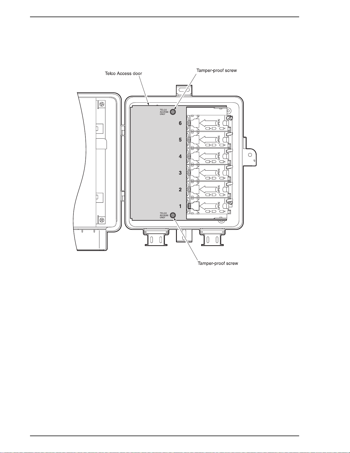
1.5 RT Enclosure. The PRL-771 RT enclosure is a weather-resistant plastic case designed for
installation on an outside wall of a business or residential building, and is hardened to withstand
environmental impact, including temperature, humidity, salt fog, water spray, UV, and insect spray.
A hinged, metal telco cover secured with two tamper-proof screws covers the wiring between the
primary protection devices and the PRL-771 electronics.
1.6 Wiring Harness. A wiring harness consisting of a cable for the six POTS pairs, a cable for the
HDSL pair, and a frame ground wire is held with a strain relief as it exits the inner metal case. The
wiring harness is factory wired to the primary protection devices for the POTS and HDSL pairs and
to the frame ground bus. An additional frame ground is attached to the metal case. The Protected
Termination Modules on the POTS lines provide gas tube over-voltage protection and an RJ-11 test
jack for isolating trouble to the network or subscriber.
1.7 Wiring. HDSL and subscriber wiring are threaded through rubber grommets at the bottom of the
enclosure. The HDSL pair from the COT is terminated on an over-voltage-protected threaded
binding post at the bottom of the enclosure and connected to the HDSL pair in the wiring harness.
Subscriber line connections are made through the right-hand side of the Protected Termination
Modules. A hinged RJ-11 jack allows the subscriber line to be disconnected from the network, or
allows for a telephone to be plugged into the PRL-771 as an aide in diagnostic tests.
1.8 Relays. Relays in the PRL-771 provide a path for metallic fallback operation. These relays are
also utilized for Subscriber Drop Testing (SDT), Mechanized Loop Testing (MLT), and 4TEL testing
in conjunction with the COLU and PG-Plus Alarm Unit (PAU).
Metallic fallback provides a direct connection from the central office to one subscriber under fault
conditions over the HDSL line. Service is provided to the subscriber assigned to the POTS #1 line in
the PRL-771. Metallic fallback is activated under any of the following conditions:
PRL-771 power failure
PLL- 720 power failure (COLU)
System turn-up (COLU installed but not PRL-771)
HDSL transceiver failure
1.9 Security. Subscribers can secure the Customer Access door by placing a padlock through the
customer-padlock hole that is drilled into the Customer Access door hasp (Figure 2). For
installations where more than one subscriber is serviced out of a single PRL-771 unit, you should
plug the customer-padlock hole in the Customer Access door hasp with a 3/8" diameter hole plug.
When more than one subscriber is serviced out of a single PRL-771 unit, the subscriber can protect
their phone line against unauthorized use by placing a padlock through the latch on the appropriate
Protected Termination Module door (Figure 3).
In either case, you have full access to the interior of the PRL-771 and to each Protected Termination
Module by removing the Telco override screw from the Customer Access door, or by removing the
two tamper-proof screws from the Telco Access door.

950-771-100 March 14, 1997 Revision 01
PG-Plus PRL-771 PairGain Engineering - Plant Series Page 3
Figure 2. Securing the Customer Access Door
Figure 3. Securing a Protected Termination Module

Revision 01 March 14, 1997 950-771-100
Page 4 PairGain Engineering - Plant Series PG-Plus PRL-771
2. Specifications
Dimensions
Height......................................................... 10.25"
Width .........................................................8.5"
Depth..........................................................4.75"
Weight........................................................5.0 lbs.
Power
HDSL Line Operating Input Voltage: ......... 135 V dc (Tip to Ring, minimum)
HDSL Line Start up Voltage:......................200 V dc (Tip to Ring, minimum)
PRL-771 Input Power:................................12.5 Watts (Tip to Ring, maximum)
HDSL
HDSL Line Code:.......................................2B1Q
HDSL Line Rate:........................................ 196 K symbols/sec (392 kbps)
HDSL Reach...............................................12.5 kft, 26 gauge
18.0 kft, 24 gauge
25.2 kft, 22 gauge
Environment
Temperature ............................................... -40ºC to +65ºC
-40ºF to +149ºF
Humidity .................................................... 5% to 95% (non-condensing)
Altitude ......................................................-60m to 4,000m
-200' to 13,000'
Vibration ....................................................NEBS
ESD............................................................Per GR-1089-CORE
Power and Lightning................................... Per GR-1089-CORE
Human Safety.............................................Per UL 1459
Emissions Radiation and Immunity............. Per FCC Part 15 for Class B equipment
Connectors
HDSL.........................................................3-terminal station protector, 3/8 inch hex nut
POTS.......................................................... Screw Terminals on RJ-11 line interface
POTS Interface
PRL-771 remote unit Supervisory Range.... 100 Ωplus 430 Ωfor handset
Detection of Loop Open..............................> 10 kΩ
Idle State Voltage....................................... -48V (minimum)
Ring Generation..........................................40 Vrms @ 20 ±3 Hz in up to 5 REN per line
(10 REN total at PRL-771 remote unit)
Ring Trip....................................................Removed in 200 ms after Loop Closure

950-771-100 March 14, 1997 Revision 01
PG-Plus PRL-771 PairGain Engineering - Plant Series Page 5
B. INSTALLATION AND TEST
3. Required Tools and Test Equipment
3.1 To install or test a PRL-771, the following tools are required:
One Telephone test set
One #2 Flat-head screwdriver
One 3/8 inch nut driver
One 5/32 inch hex key, drilled for tamper-proof fasteners
4. Inspecting Your Shipment
4.1
Upon receipt of the equipment:
•Unpack each container and visually inspect it for signs of damage. If the equipment has been
damaged in transit, immediately report the extent of damage to the transportation company and
to PairGain. Order replacement equipment if necessary.
•Check the contents versus the packing list to ensure complete and accurate shipment. If the
shipment is short or irregular, contact PairGain as described in the section entitled "Warranty."
If you must store the equipment for a prolonged period, store the equipment in its original
container inside a building or under cover.
5. Installation
5.1 Safety Precautions. To ensure the safety of personnel and equipment, carefully observe the
following safety rules:
Be careful when installing or modifying telephone lines. Dangerous voltages
can be present. It is unsafe to install telephone wiring during a lightning storm.
Always disconnect all telephone lines and power connections before servicing
or disassembling this equipment.
For performance and safety reasons, only power supplies listed for use with
telephone equipment by a locally recognized organization should be used with
PairGain equipment.
All wiring external to the product should follow the local wiring codes.
Always treat the HDSL pair as if it were live with high voltage present. When
installing an HDSL pair which is already connected to a COLU, caution must be
used as dangerous voltages are present on the HDSL pair. The COLU, unless
previously disabled via craft provisioning, periodically attempts to power up the
PRL-771 by applying + 100 V dc to the HDSL pair. The COLU also initiates a
start-up after a momentary short has been applied to the HDSL pair. The COLU
responds with start-up voltage immediately upon removal of the short.

Revision 01 March 14, 1997 950-771-100
Page 6 PairGain Engineering - Plant Series PG-Plus PRL-771
5.2 Disable the line power. To disable the line power, use a test lead with two clips to short the
HDSL Tip and Ring conductors:
1Attach one test-lead clip to the Tip conductor.
2Attach the second test-lead clip to the Ring conductor.
This ensures that the potential difference between Tip and Ring is zero. The PRL-771 and the
PLL-721 COLU go to the metallic fallback to POTS state, and remain in metallic fallback until
the short is removed. Once the PLL-721 COLU senses the short (or off hook) condition has
been removed, it initiates a power up sequence to start the PRL-771.
5.3 Install the PRL-771 RT enclosure. Use the two #10 x 1.5" wood screws and flat washers
provided in the PRL-771 Mounting Kit to attach the PRL-771 RT enclosure to the side of the
customer residence (see Figure 4). For installation on stucco or other suitable surface, use the two
PairGain provided #10 x 1" anchor nuts.
Install the PRL-771 RT enclosure only as shown in Figure 4, with all access
openings facing down. Otherwise, possibly damaging materials (such as fluids)
can enter the PRL-771 RT enclosure.
Figure 4. Installing the PRL-771 RT Enclosure

950-771-100 March 14, 1997 Revision 01
PG-Plus PRL-771 PairGain Engineering - Plant Series Page 7
5.4 PRL-771 Reference Label. During installation, refer to the PRL-771 reference label (Figure 5)
affixed inside the Customer Access door. The middle section of the PRL-771 reference label
identifies the Frame Ground and HDSL Tip and Ring wires as well as the wire color code for the six
POTS lines.
Figure 5. PRL-771 Reference Label

Revision 01 March 14, 1997 950-771-100
Page 8 PairGain Engineering - Plant Series PG-Plus PRL-771
5.5 Attach the Frame-Ground Wire:
1Use a 5/32" tamper-proof hex key to loosen the two tamper-proof screws on the Telco Access
door, then open the Telco Access door (Figure 6).
Figure 6. Opening the Telco Access Door

950-771-100 March 14, 1997 Revision 01
PG-Plus PRL-771 PairGain Engineering - Plant Series Page 9
2Use a pencil to punch a small hole in the bottom of the rubber grommet on the left-hand bottom
side of the PRL-771 RT enclosure (Figure 7).
3Insert the frame-ground wire into the PRL-771 RT enclosure through the pencil hole made in
step 1. A 10 AWG copper frame ground wire is recommended.
4Loosen and remove from the ground-binding post the top nut and three flat washers.
5Loop the frame-ground wire around the ground-binding post, then replace and tighten the
hardware removed in step 4, in reverse order.
Figure 7. Attaching the Frame-Ground Wire

Revision 01 March 14, 1997 950-771-100
Page 10 PairGain Engineering - Plant Series PG-Plus PRL-771
5.6 Attach the HDSL Tip and Ring Wires:
Always treat the HDSL pair as if it were live with high voltage present. If you
have not shorted the HDSL Tip and Ring conductors as described in section 5.2,
do not connect the HDSL Tip and Ring wires. Otherwise you may receive a
severe electrical shock.
1Use a pencil to punch a second small hole in the bottom of the rubber grommet on the left-hand
bottom side of the PRL-771 RT enclosure.
2Insert the HDSL Tip and Ring wires into the pencil hole made in step 1.
3Loosen only the top nut on the Tip and Ring gas tube protection binding posts (Figure 8).
4Insert and then loop in a clockwise direction the HDSL Tip and Ring wires between the top two
washers on the appropriate binding post, then tighten the nut you loosened in step 3.
Figure 8. Attaching the HDSL Tip and Ring Wires

950-771-100 March 14, 1997 Revision 01
PG-Plus PRL-771 PairGain Engineering - Plant Series Page 11
5.7 Attach the subscriber analog POTS drop:
1Lift the appropriate Protected Termination Module door (Figure 9).
Figure 9. Inserting the POTS Wires
2Insert the POTS wire pair through the cutout on the right side of the Protected Termination
Module door (Figure 10).
3Connect the Tip conductor to the green terminal lug on the Protected Termination Module.
4Connect the Ring conductor to the red terminal lug on the Protected Termination Module.
Figure 10. Attaching the POTS Wire Pair

Revision 01 March 14, 1997 950-771-100
Page 12 PairGain Engineering - Plant Series PG-Plus PRL-771
6. Turn up and Testing
6.1 To turn up and test the PG-Plus system:
1Open all the Protected Termination Module doors to ensure there are no off-hook conditions
present from the subscriber lines.
2Remove the short from the HDSL Tip and Ring conductors.
The following start-up sequence should occur:
The COLU responds with start-up voltage immediately.
The PRL-771 detects HDSL line voltage, drops the metallic fallback to POTS, then initiates
the HDSL start-up sequence.
The POWER LED flashes green and the ACTIVITY LED is solid green.
Start-up is complete once the POWER LED is on solid green and the ACTIVITY and STATUS
LEDs are both off.
3Close all the Protected Termination Module doors.
4Follow standard POTS procedures to check the overall performance of the POTS channel
coming in and out, including ringing, dialing, and transmission. Use the customer's telephone if
possible.
7. Close the Housing
7.1 To close the housing:
1Close the Telco Access door and secure its two tamper-proof screws.
2Verify that the screws on the Telco Access door are completely seated to avoid interference with
the PRL-771 RT enclosure cover.
3Close the housing cover and secure its tamper-proof screw.
Failure to close the PRL-771 Telco Access door or housing cover leaves the
PRL-771 interior exposed to the environment. This shortens the life span of the
PRL-771.

950-771-100 March 14, 1997 Revision 01
PG-Plus PRL-771 PairGain Engineering - Plant Series Page 13
8. Fault Isolation
8.1 The circuit board metal enclosure has a System Status window through which Status LEDs may be
viewed. The Status LEDs indicate different system states such as status of power, and subscriber line
activity including on-hook, off-hook, ringing, and subscriber drop test activity. The top portion of
the PRL-771 reference label provides a guide to what the Status LEDs indicate (Figure 11).
Figure 11. PRL-771 Status Window
If the PRL-771 fails to indicate power on (as evidenced by the Power LED being off), perform the
following diagnostic and repair operations:
1Verify that the PRL-771 and its corresponding COLU are installed on the same pair.
2Verify that the corresponding COLU is installed and turned up, and that the HDSL Periodical
Power Up option is enabled.
3Verify that the signal loss on the pair is no more than 41 dB at 196 kHz.
4Replace the PRL-771.
5Replace the corresponding COLU.
6Check for a short placed on the HDSL Tip and Ring conductors, and remove if necessary.
7Check for HDSL cable fault, and replace if necessary.

Revision 01 March 14, 1997 950-771-100
Page 14 PairGain Engineering - Plant Series PG-Plus PRL-771
9. Technical Support
9.1 PairGain Technical Assistance is available 24-hours-a-day, 7-days-a-week by contacting PairGain
Customer Service Engineering group at:
Telephone: (800) 638-0031 or (714) 832-9922
Fax: (714) 832-9924
9.2 During normal business hours (8:00 AM to 5:00 PM, Pacific Time, Monday - Friday, excluding
holidays), technical assistance calls are normally answered directly by a Customer Service Engineer.
At other times, a request for technical assistance is handled by an on-duty Customer Service
Engineer through a callback process. This process normally results in a callback within 30 minutes
of initiating the request.
9.3 In addition, PairGain maintains a computer bulletin board system for obtaining current information
on PairGain products, product troubleshooting tips and aids, accessing helpful utilities, and for
posting requests or questions. This system is available 24-hours-a-day by calling (714) 730-3299.
Transmission speeds up to 28.8 kbps are supported with a character format of 8-N-1.
10. Certification
10.1 FCC Compliance. The PG-Plus PRL-771 Remote Line unit complies with the limits for a Class B
digital device,
pursuant to Part 15 of the FCC rules. These limits are designed to provide reasonable
protection against harmful interference in a residential installation. This equipment generates, uses
and can radiate radio frequency energy and, if not installed and used in accordance with the
instructions, may cause harmful interference to radio communications. However, there is no
guarantee that interference will not occur in a particular installation. If this equipment does cause
harmful interference to radio or television reception, which can be determined by turning the
equipment off and on, the user is encouraged to try to correct the situation by one or more of the
following measures:
Reorient or relocate the receiving antenna.
Increase the separation between the equipment and the receiver.
Consult the dealer or an experienced radio or television technician for help.
10.2 Modifications. The FCC requires the user to be notified that any changes or modifications made to
this device that are not expressly approved by PairGain Technologies, Inc. may void the user's
authority to operate the equipment.
10.3 All wiring external to the product(s) should follow the provisions of the current edition of the
National Electrical Code.

950-771-100 March 14, 1997 Revision 01
PG-Plus PRL-771 PairGain Engineering - Plant Series Page 15
11. Warranty
11.1 PairGain Technologies warrants this product to be free of defects and to be fully functional for a
period of 60 months from the date of original shipment, given proper customer installation and
regular maintenance. PairGain will repair or replace any unit without cost during this period if the
unit is found to be defective for any reason other than abuse or improper use or installation.
11.2 Do not try to repair the unit. If it fails, replace it with another unit and return the faulty unit to
PairGain for repair. Any modifications of the unit by anyone other than an authorized PairGain
representative voids the warranty.
11.3 If a unit needs repair:
1Call PairGain for a Return Material Authorization (RMA) number at (800) 638-0031.
2Return the defective unit, freight prepaid, along with a brief description of the problem, to:
PairGain Technologies, Inc.
2120 Ritchey Street
Santa Ana, CA 92705-5101
ATTN: Repair and Return Dept.
11.4 PairGain continues to repair faulty modules beyond the warranty program at a nominal charge.
Contact your PairGain sales representative for details and pricing.
C. ABBREVIATIONS
12. Abbreviations
CO Central Office
COLU Central Office Line Unit
COT Central Office Terminal
ESD Electro-Static Discharge
HDSL High-bit-rate Digital Subscriber Line
LED Light-Emitting Diode
MLT Mechanized Loop Test
PAU PG-Plus Alarm Unit
POTS Plain Old Telephone Service
PRL PG-Plus Remote Line unit
RLU Remote Line Unit (circuitry only)
RMA Return Materials Authorization
RT Remote Terminal (enclosure and RLU inclusive)
SDT Subscriber Drop Test

This manual suits for next models
1
Table of contents
Other CopperOptics Remote Control manuals