manuals.online logo
Brands
  1. Home
  2. •
  3. Brands
  4. •
  5. CORNING
  6. •
  7. Control Unit
  8. •
  9. CORNING CCH User manual

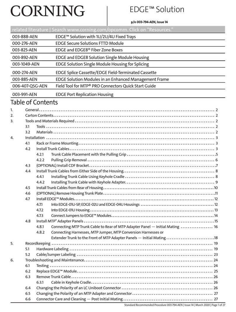
CORNING CCH User manual

Other CORNING Control Unit manuals

CORNING MobileAccess1000 Operator's manual

CORNING

CORNING MobileAccess1000 Operator's manual

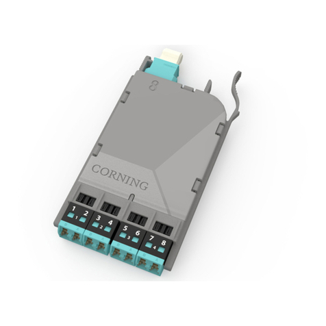
CORNING EDGE8-01U User manual

CORNING

CORNING EDGE8-01U User manual

CORNING CWDM MUX User manual

CORNING

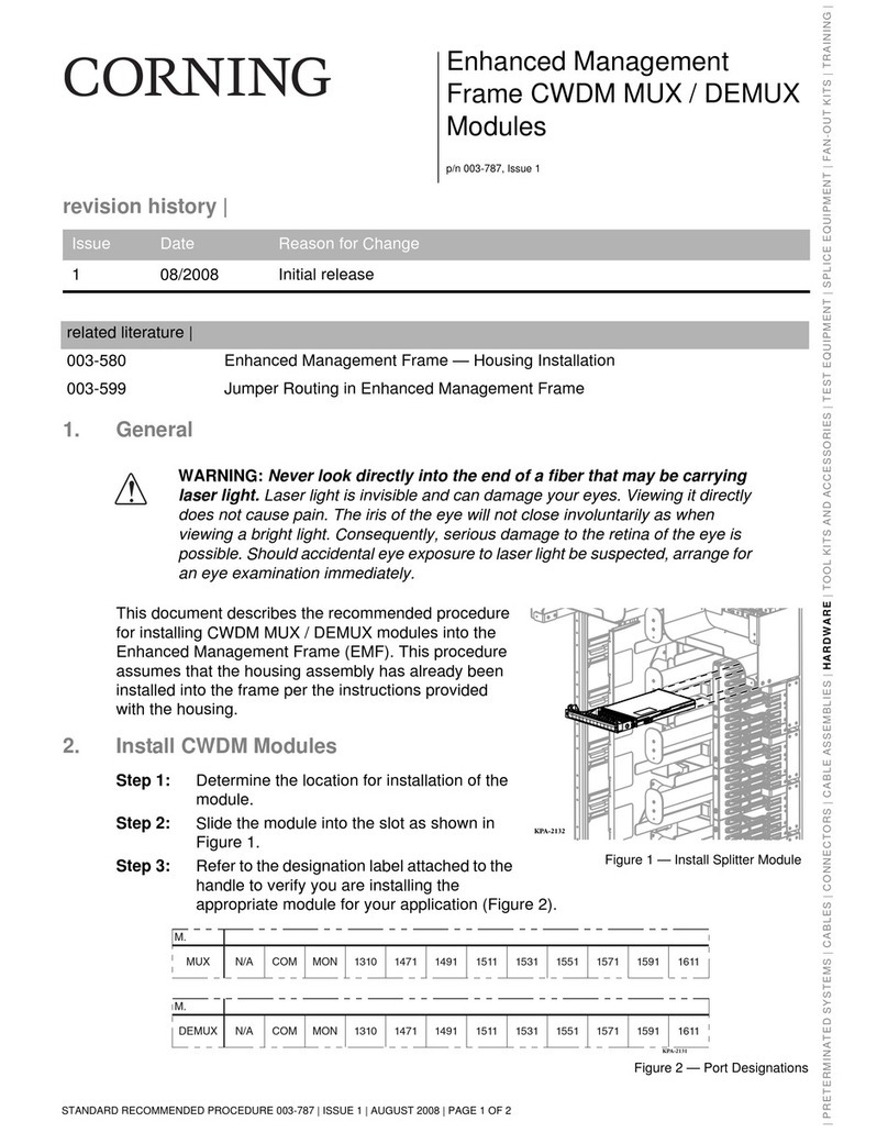
CORNING CWDM MUX User manual

CORNING Pretium EDGE ETM-7B-G User manual

CORNING

CORNING Pretium EDGE ETM-7B-G User manual

CORNING EDGE Series User manual

CORNING

CORNING EDGE Series User manual

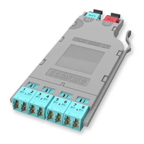
CORNING EDGE8 MTP User manual

CORNING

CORNING EDGE8 MTP User manual

Popular Control Unit manuals by other brands

Seitz 14A80 user manual

Seitz

Seitz 14A80 user manual

Wilo RS485 Installation and operating instructions

Wilo

Wilo RS485 Installation and operating instructions

Becker CentralControl CC41 Commissioning Instruction

Becker

Becker CentralControl CC41 Commissioning Instruction

SICK CDB650 operating instructions

SICK

SICK CDB650 operating instructions

Panduit NetKey NKP5E88M Series installation instructions

Panduit

Panduit NetKey NKP5E88M Series installation instructions

MX Options Concentric Petite Fitting instructions

MX

MX Options Concentric Petite Fitting instructions

Clean Water Systems Fleck 2510 Installation & start?up guide

Clean Water Systems

Clean Water Systems Fleck 2510 Installation & start?up guide

Fairchild FSB44104A user guide

Fairchild

Fairchild FSB44104A user guide

LEGRAND Wattstopper LMIN-104 installation instructions

LEGRAND

LEGRAND Wattstopper LMIN-104 installation instructions

PMK ATT10BNCS instruction manual

PMK

PMK ATT10BNCS instruction manual

Tektronix TDS3FFT user manual

Tektronix

Tektronix TDS3FFT user manual

Woodward easYgen Technical manual

Woodward

Woodward easYgen Technical manual

Balluff BNI EIP-502-105-R015 user guide

Balluff

Balluff BNI EIP-502-105-R015 user guide

NXP Semiconductors TWR-LS1021A Getting started

NXP Semiconductors

NXP Semiconductors TWR-LS1021A Getting started

Advantech PCM-3117 Startup manual

Advantech

Advantech PCM-3117 Startup manual

Danfoss MCO 101 manual

Danfoss

Danfoss MCO 101 manual

Moons' Lin Engineering R701P user manual

Moons'

Moons' Lin Engineering R701P user manual

Aventics RV1 operating instructions

Aventics

Aventics RV1 operating instructions

manuals.online logo
manuals.online logoBrands
  • About & Mission
  • Contact us
  • Privacy Policy
  • Terms and Conditions

Copyright 2025 Manuals.Online. All Rights Reserved.

CCH Modules with LC Duplex
Shuttered Adapters
cat. number 003-122, Issue 1
STANDARD RECOMMENDED PROCEDURE 003-122 | ISSUE 1 | MAY 2009 | PAGE 1 OF 4STANDARD RECOMMENDED PROCEDURE 003-122 | ISSUE 1 | MAY 2009 | PAGE 4 OF 4
revision history |
1. General
This document describes the installation and maintenance of the 12 and
24-fiber versions of CCH Plug & Play™ System modules equipped with LC
duplex shuttered connector adapters (Figure 1).
The shuttered LC adapters used in these modules eliminate the use of
easily misplaced individual dust caps and ensure that the adapters remain
clean when not in use.
IMPORTANT: CCH modules are factory sealed. Breaking the seal will void the
manufacturer’s warranty.
Issue Date Reason for Change
1 May 2009 Initial Release
W
A
R
R
A
N
T
Y
VOID
Corning Cable Systems LLC •PO Box 489 •Hickory, NC 28603-0489 USA
800-743-2675 •FAX: 828-901-5973 •International + 1-828-901-5000 • www.corning.com/cablesystems
Corning Cable Systems reserves the right to improve, enhance, and modify the features and specifications of Corning Cable
Systems’products without prior notification. MTP is a registered trademark of US Conec Ltd. All other trademarks are the
property of their respective holders. Corning Cable Systems is ISO 9001 certified.
©2009 Corning Cable Systems LLC. All rights reserved.
6. Maintenance
The most likely cause of a problem with a module is connector end-face
contamination. Always keep clean dust caps on the module’s MTP connector
adapters and the trunk’s connectors when they are unmated, and clean the
connectors before each mating.
To clean LC duplex connectors
and the LC shuttered adapters on
the front of the CCH module, use
a CLEANER-PORT-LC tool as
described in its instructions.
To clean the MTP connectors and
adapters, use an MTP connector
cleaning tool (p/n 2104466-01)
as described in its instructions
(Figure 4).
Periodically check the fiber optic cable to make sure bends do not exceed the
minimum bend radius. Check the trunk for unnecessary strain. Check the trunk
cable for crimping or crushing.
CLEANER-PORT-LC
2104466-01
| PRETERMINATED SYSTEMS | CABLES | CONNECTORS | CABLE ASSEMBLIES | HARDWARE | TOOL KITS AND ACCESSORIES | TEST EQUIPMENT | SPLICE EQUIPMENT | FAN-OUT KITS | TRAINING |
Figure 1 - 12 and 24-fiber CCH Modules
Figure 4 - Connector cleaning tools
STANDARD RECOMMENDED PROCEDURE 003-122 | ISSUE 1 | MAY 2009 | PAGE 2 OF 4 STANDARD RECOMMENDED PROCEDURE 003-122 | ISSUE 1 | MAY 2009 | PAGE 3 OF 4
5. Connecting the Module with an MTP® Trunk
Step 1: Standard MTP connectors mated into the adapters on the back
of a CCH module have precision guide pins. To secure a
non-pinned MTP connector from a trunk into an adapter:
a) Remove the dust caps from the MTP connector on the end
of the trunk.and the MTP adapter on the back of the CCH
connector module.
b) To install the connector, grasp the connector by its boot
which is marked “push.”Align the key in the connector
with the slot in the adapter and push the connector until it
clicks in place (Figure 3).
Step 2: To unplug the connector, grasp the slider which is marked
“pull”and pull the connector out of the adapter.
DO NOT PULL ON THE BOOT TO UNPLUG THE
CONNECTOR.
Boot
Slider
Adapter
Figure 3 - MTP installation
2. Precautions
Laser Precautions
WARNING: Laser light can damage your eyes.Laser light is invisible.
Viewing it directly does not cause pain. The iris of the eye will not close
involuntarily as when viewing a bright light. Consequently, serious damage
to the retina of the eye is possible. Never look into the end of a fiber or at a
connector in a microscope which may have a laser coupled to it. Should
accidental eye exposure to laser light be suspected, arrange for an eye
examination immediately.
Fiber Optic Cable Precautions
CAUTION: Fiber optic cable is sensitive to excessive pulling, bending, and
crushing forces. Consult the cable specification sheet for the cable you are
installing. Do not bend cable more sharply than the minimum recommended
bend radius. Do not apply more pulling force to the cable than specified. Do
not crush the cable or allow it to kink. Doing so may cause damage that can
alter the transmission characteristics of the cable - the cable may have to
be replaced.
3. Tools and Materials
The following tools and materials, purchased separately, are required to complete
this procedure:
• LC cleaning tool, Corning Cable Systems p/n CLEANER-PORT-LC
• MTP cleaning tool, p/n 2104466-01
4. Module Installation
Step 1: Remove a blank panel by pulling out both of the plungers of the
panel’s push/pull fasteners (Figure 2).
Step 2: Position the module’s fasteners over the proper holes in the
mounting bracket and push in all the plungers to lock the
module in place.
Secured Open
Figure 2 - Push-pull fasteners