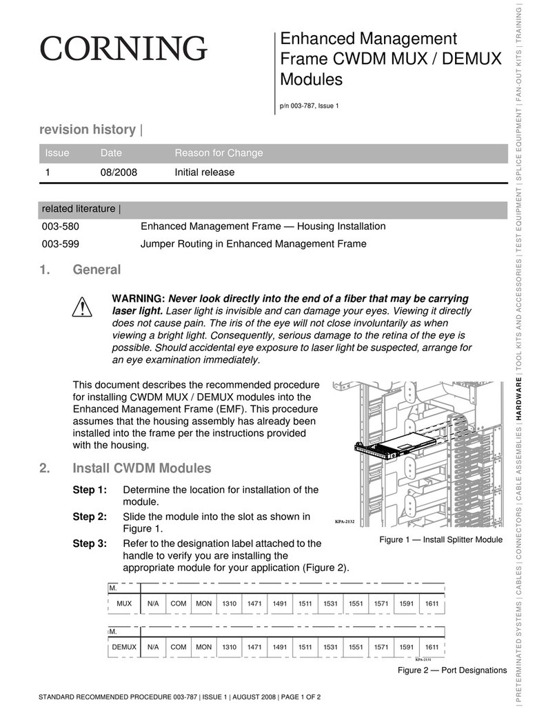
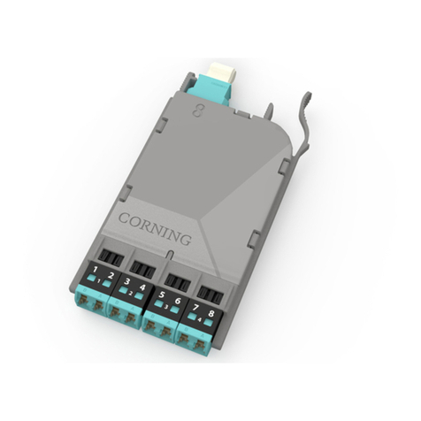
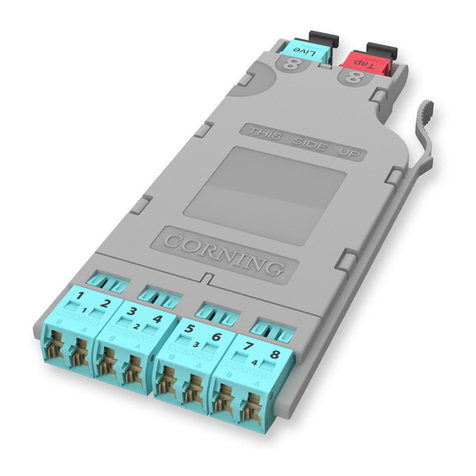
CORNING EDGE Series User manual

Standard Recommended Procedure 003-794-AEN | Issue 14 | March 2020 | Page 1 of 27
EDGE™ Solution
Table of Contents
1. General.................................................................................................. 2
2. Carton Contents.......................................................................................... 2
3. Tools and Materials Required .............................................................................. 2
3.1 Tools .............................................................................................. 2
3.2 Materials .......................................................................................... 2
4. Installation .............................................................................................. 3
4.1 Rack or Frame Mounting............................................................................ 3
4.2 Install Trunk Cables................................................................................. 3
4.2.1 Trunk Cable Placement with the Pulling Grip ..................................................5
4.2.2 Pulling Grip Removal ....................................................................... 6
4.3 (OPTIONAL) Install CDF Bracket .......................................................................7
4.4 Install Trunk Cables from Either Side of the Housing................................................... 8
4.4.1 Installing Trunk Cable Using Keyhole Cradle .................................................. 8
4.4.2 Installing Trunk Cable with Keyhole Adapter.................................................. 9
4.5 Install Trunk Cables from Rear of Housing....................................................................10
4.6 (OPTIONAL) Remove Housing Trunk Plate .....................................................................11
4.7 Install EDGE™ Modules......................................................................................12
4.7.1 Into EDGE-01U-SP, EDGE-02U and EDGE-04U Housings .............................................12
4.7.2 Into EDGE-01U Housing ............................................................................13
4.7.3 Connect Jumpers to EDGE™ Modules...............................................................14
4.8 Install MTP®Adapter Panels .........................................................................15
4.8.1 Connecting MTP Trunk Cable to Rear of MTP Adapter Panel —Initial Mating .................. 16
4.8.2 Connecting Harnesses, MTP Jumper, MTP Conversion Harnesses or
Extender Trunk to the Front of MTP Adapter Panels —Initial Mating ...........................18
5. Recordkeeping .......................................................................................... 19
5.1 Hardware Labeling ................................................................................ 19
5.2 Cable/Jumper Labeling ............................................................................ 23
6. Troubleshooting and Maintenance........................................................................24
6.1 Testing ........................................................................................... 24
6.2 Replace EDGE™ Module............................................................................ 25
6.3 Remove Trunk Cable ...............................................................................26
6.3.1 Cable in Keyhole Cradle....................................................................26
6.4 Changing the Polarity of an LC Uniboot Connector ...................................................26
6.5 Changing the Polarity of an MTP Adapter and Connector ............................................. 27
6.6 Connector Care and Cleaning —Post Initial Mating .................................................. 27
related literature | Search www.corning.com/opcomm. Click on “Resources.”
003-888-AEN EDGE™ Solution with 1U/2U/4U Fixed Trays
000-276-AEN EDGE Secure Solutions FTTD Module
003-825-AEN EDGE and EDGE8®Fiber Zone Boxes
003-892-AEN EDGE and EDGE8 Solution Single Module Housing
003-1049-AEN EDGE Solution Single Module Housing for Splicing
000-274-AEN EDGE Splice Cassette/EDGE Field-Terminated Cassette
003-885-AEN EDGE Solution Modules in an Enhanced Management Frame
006-407-QSG-AEN Field Tool for MTP® PRO Connectors Quick Start Guide
003-991-AEN EDGE Port Replication Housing
pp/n 003-794-AEN, Issue 14

Standard Recommended Procedure 003-794-AEN | Issue 14 | March 2020 | Page 2 of 27
1. General
This document describes installation of the EDGE™ 1U, 1U-SP, 2U, and 4U Housing Solutions (Figure 1). Except
where installation of another housing is unique, only the 4U housing is illustrated.
2. Carton Contents
• Housing, either 1U, 1U-SP, 2U, or 4U rack-height
• Mounting hardware kit, either for rack or frame
• (1U-SP, 2U and 4U housings ONLY) (2) Fiber management ngers
3. Tools and Materials Required
3.1 Tools
• Phillips screwdriver
• Reel stand
3.2 Materials
• Hook-and-loop straps
Figure 1 — EDGE Housings

Standard Recommended Procedure 003-794-AEN | Issue 14 | March 2020 | Page 3 of 27
4. Installation
4.1 Rack or Frame Mounting
Step 1: Identify the position on the rack where the housing will be installed and partially install screws to rest
the mounting brackets on Figure 2.
Step 2: Move brackets forwards or backwards for desired frontal projection and rest the mounting brackets
behind the screw heads just installed in the rack.
Step 3: Install screws into the rack through the mounting brackets.
Step 4: If installing a 2U or 4U housing, slide the ber management ngers onto the housing.
NOTE: Installation of ber management ngers is essential to ensure proper jumper management.
4.2 Install Trunk Cables
The EDGE™ Trunk Cable is supplied with factory-installed protection/pulling grips (Figure 3) to protect the
connectors and their bers by coupling the pulling load back to the cable. The cradle is used to install the
furcation plug into the housing.
Figure 2 — Rack or Frame Mounting
Figure 3 — Cable with Pulling Grips

Standard Recommended Procedure 003-794-AEN | Issue 14 | March 2020 | Page 4 of 27
Weather Precautions
• Always follow the recommended storage temperature guidelines for the cable when storing
a trunk/pigtail. Each cable type will have a storage temperature rating that can be found on
the product specication sheets. Storage outside of these ranges can cause damage to the
cables.
• Cable type, pulling grip and reel material dictate indoor or outdoor storage. Plywood reels
should never be stored outdoors. Doing so may cause damage to the reel. Cables designed
specically for indoor use should never be stored outdoors. Indoor cables are also not UV
rated, and jacket damage can occur from storing indoor cables in sunlight. Not all pulling grips
are watertight and suitable for exposure to weather. Trunks/pigtails with non-watertight grips
will need to be stored inside, even though the cable may be suitable for outdoor storage.
Trunks greater than 144 bers do not have watertight pulling grips. These trunks should be
stored in a dry location to ensure proper performance of the connectors.
Reel Handling
• Always lift a plywood or wooden reel by both anges. Do not pick up a reel by one ange.
Picking up a reel by one ange can cause the reel bolts to loosen leading to cable damage.
• Never drop a reel. When a reel is dropped, damage to the cable can occur and ange bolts
can loosen. Any dropped reel should be thoroughly evaluated for cable/reel damage.
• Do not allow reels to bump into one another. Allowing the anges to rub or bump the cable
can cause cable or ber damage.
• Pay attention to reel labels. Reels should always be stored in the orientation outlined on
the reel. Observe “This End Up” arrows on reels or boxes.
• Ensure that all ange bolts are tight prior to loading a reel for pulling. Changes in
temperature and humidity can cause the wooden/cardboard components of the reel to expand
and contract allowing the ange bolts to loosen over time. Loose ange bolts may cause the
cable to become entangled and possibly damage the cable during installation.
For detailed information on cable placement, and a comprehensive list of applicable safety precautions,
refer to SRP-005-014, Fiber Optic Cable Placing - Intrabuilding. It is necessary to have radio or other two way
communications between pull points. Should a kink or other pulling problem occur, instant communication is
vital to stop the pulling operation to prevent cable and/or connector damage.
CAUTION: Do not use any type of lubricant when installing this series of pulling grip.
CAUTION: These grips are intended to be placed and pulled by hand. Do not use any mechanical
pulling devices on this series of grip.
CAUTION: This preconnectorized pulling grip has a maximum tensile rating of 100 pounds (44.5 kg).
NEVER EXCEED THIS TENSION DURING INSTALLATION. The pulling grip has a minimum bend radius of
18 inches (45.72 cm). Refer to the EDGE specication sheet for cable/grip dimensions and appropriate
duct sizes.
IMPORTANT: The pulling grips installed on preconnectorized cables contain the
connectors and their sub-units. Unlike conventional pulling grips, do not cut o the grip
and cable inside it upon the completion of cable installation. Remove the pulling grip
from over the connectors and sub-units only as described in this procedure. Failure to do
so may result in damage or loss of the connector assemblies.
Do not attempt to disassemble the pulling grip before the cable is pulled into place.
Doing so may cause the pulling grip to fail.

Standard Recommended Procedure 003-794-AEN | Issue 14 | March 2020 | Page 5 of 27
CAUTION: Fiber optic cable is sensitive to excessive pulling, bending, and crushing forces. Consult the
cable specication sheet for the cable you are installing. Do not bend the cable more sharply than the
minimum recommended bend radius. Do not apply more pulling force to the cable than specied. Do
not crush the cable or allow it to kink. Doing so may cause damage that can alter the transmission
characteristics of the cable; the cable may have to be replaced.
4.2.1 Trunk Cable Placement with the Pulling Grip
NOTE: This procedure assumes that a pull line has been
placed in the duct route and that the equipment
necessary to maintain the bend-radius of the
pulling grip is in position.
Step 1: If necessary, remove the corrugated reel from
its protective shipping box or pallet.
Step 2: Place the cable reel on a reel stand so that the
pulling grip/cable will pay-o the top of the
reel (Figure 4).
NOTE: Cables greater than or equal to 22.9 m (75 ft) ship
in a bag in a box.
Step 3: Attach a pull line to the pulling loop at the end
of the sleeve (Figure 5).
Step 4: Place the cable using your company’s standard practice,
taking care not to exceed either the minimum bend
radius or tensile rating of the grip.
Figure 4 — Reel Stand and Cable Route
Figure 5 — Pull Line

Standard Recommended Procedure 003-794-AEN | Issue 14 | March 2020 | Page 6 of 27
4.2.2 Pulling Grip Removal
Step 1: Remove the pull line and clean any dirt or debris from the outer surfaces of the sleeve.
IMPORTANT: Disassemble the pulling sleeve on a work surface free from dirt, excessive heat, or any solvents.
Step 2: Lift the hook-and-loop aps to expose
the zipper pull. While holding the sleeve’s
pulling loop with one hand, unzip the
sleeve (Figure 6).
Step 3: Remove the cloth sleeve from around the
grip.
Step 4: With the grip lying on a work surface, grasp the
coupler at the cable-end of the trunk cable. With
a slight twisting motion, pull the corrugated
tube away from the coupler with your other
hand (Figure 7).
Step 5: Slowly slide the tubing away from the coupler
and its connector legs (Figure 8).
Step 6: Use the tabs on the furcation end of the coupler to
separate the coupler’s two halves.
Step 7: Remove the coupler halves from the trunk furcation body
and dispose of the coupler assembly (Figure 9).
Figure 6 — Unzipping the Sleeve
Figure 7 — Grip Disassembly
Figure 8 — Tubing Removal
Figure 9 — Remove Coupler Halves

Standard Recommended Procedure 003-794-AEN | Issue 14 | March 2020 | Page 7 of 27
96- and 144-ber Trunks:
Step 8: Starting with the mesh bag closest to the furcation body, remove the tape and mesh to expose the
rst set of three folded legs (Figure 10). Unfold the legs from around the bend control device.
Repeat this step on the middle mesh bag, and then conclude by removing the end mesh bag.
4.3 (OPTIONAL) Install CDF Bracket
An optional CDF bracket may be installed external to the housing on the frame to provide additional cable
trunk installation positions and/or strain-relief. It supports incoming cable installation from the top or bottom
of the frame into the housing. The bracket can hold keyhole cradles or U-clip furcation trunk holders (ordered
separately) and is available in three sizes:
• EDGE-CDF-RJ04-BKT — 4-position furcation trunk holder
• EDGE-CDF-RJ08-BKT — 8-position furcation trunk holder
• EDGE-CDF-RJ12-BKT — 12-position furcation trunk holder
CDF brackets support use of extender trunks. If using an IBU (vertical manager) between frames, extender
trunks mounted to the CDF bracket on the back side of the frame must transition to the front using a “pass-
through” IBU system.
Step 1: Align bracket within the same height of the 4U housing.
Step 2: Install bracket using two 12-24 screws (Figure 11). Allow enough clearance when routing trunks from
the bracket into the housing to ensure bend radius is maintained when trunks enter the housing.
NOTE: If greater bend radius control of cable is required, position the bracket slightly above or below the roof of
the housing, depending upon the direction the cable is entering the housing.
Step 3: Insert furcation plug into cradle as seen in Figure 12 or Figure 13 and mount cradle onto CDF bracket
(Figure 11).
Step 4: Then route trunks inside the housing through the brushed cable entry slots.Terminate the MTP
connector at the back of the LC module or MTP adapter panel.
NOTE: In some cases, variations in the length of the trunk leg make it necessary to mount the trunk cradle
further out on the CDF bracket closer to the cable entry slot to avoid pulling on the leg when accessing the
tray from the front side of the housing.
Figure 10 — Mesh Bag Removal

Standard Recommended Procedure 003-794-AEN | Issue 14 | March 2020 | Page 8 of 27
4.4 Install Trunk Cables from Either Side of the Housing
If necessary to install trunk cables from the rear of a housing, refer to Section 4.5 for details on reorienting the
backplates to accommodate rear cable entry.
In a 4U housing trunk cables may be installed into the backplates in the top of the housing in an upside-down
orientation, if desired or necessary, to accommodate additional cables.
4.4.1 Installing Trunk Cable Using Keyhole Cradle
Step 1: Remove the access or rear cover from the housing to
reach the backplate (Figure 1).
Step 2: Open cradle provided inside the reel and press each
trunk cable furcation plug into cradle (Figure 12
- double-stack cradle or Figure 13 - single-stack
cradle).
NOTE: One double-stack cradle (shown in Figure 12) is
provided with the trunk cable.
.
Figure 11 — Install CDF Bracket
Figure 12— Double-stack Keyhole Cradle

Standard Recommended Procedure 003-794-AEN | Issue 14 | March 2020 | Page 9 of 27
Step 3: Open rear housing door. Route cables into housing through side openings.
Step 4: Insert cradle feet into backplate and slide into slots to lock in place.
Step 5: Repeat for all trunk cables and allow connectorized MTP legs to ow out the rear of the housing until
ready to mate in the appropriate module or panel.
4.4.2 Installing Trunk Cable with Keyhole Adapter
Step 1: Orient keyhole adapter to where leg side of trunk is near keyhole adapter release tabs (Figure 14).
Step 2: Align groove on furcation body with ridge in keyhole adapter.
Step 3: Once the groove is aligned, slide down and back until furcation body is completely mounted on the
keyhole adapter.
Step 4: Align keyhole adapter with mounting plate. Push down and slide keyhole adapter back until it locks
into place.
Figure 14 – Install Trunk Cable with Keyhole Adapter
Figure 13 — Install Trunk Cables with Keyhole Cradle

Standard Recommended Procedure 003-794-AEN | Issue 14 | March 2020 | Page 10 of 27
4.5 Install Trunk Cables from Rear of Housing
If rear cable entry into the housing is desired or necessary, the backplates must be turned 180 degrees before
installing the cables.
Step 1: Remove existing backplates by removing the four screws (Figure 15).
Step 2: Turn the backplate 90 degrees as shown and reinstall the four screws.
Step 3: Insert cradle feet into backplate as shown in Figure 13 or Figure 14 for your cradle type.
Figure 15 — Reorient Backplate

Standard Recommended Procedure 003-794-AEN | Issue 14 | March 2020 | Page 11 of 27
4.6 (OPTIONAL) Remove Housing Trunk Plate
If cable entry strain-relief is accomplished in a location external to the housing, the trunk plate may be removed
to allow more room behind the housing (Figure 16).
Step 1: (For 4U housing only) Remove side panel from each side of the housing.
Step 2: Remove any screws holding the access panels to the housing.
Step 3: Remove any screws holding the trunk plate to the housing.
Figure 16 — Remove Back Deck

Standard Recommended Procedure 003-794-AEN | Issue 14 | March 2020 | Page 12 of 27
4.7 Install EDGE™ Modules
4.7.1 Into EDGE-01U-SP, EDGE-02U and EDGE-04U Housings
Step 1: Remove the MTP®connector dust cap by pulling on the dust cap while holding the connector body.
For the initial mating, do not clean or scope connectors. Corning®CleanAdvantage™connectors are
shipped with an optimized dust cap to maintain cleanliness for the rst use.
Step 2: Mate the MTP connector(s) into the adapter(s) at the back of the module (Figure 17) with the MTP key
down/opposite the module label.
Step 3: Starting with lower right corner (Tray 1, slot A), insert module from the rear until it locks into place.
Load all trays from right to left, bottom to top in the housing, as seen from the back.
Step 4: Loop slack as shown in Figure 17, leaving enough slack to pull out trays without violating the
minimum bend radius.
Step 5: Repeat for all modules.
Step 6: Loosely capture ber slack with hook-and-loop straps (Figure 17).
EDGE Module Installation
Figure 17 — Load EDGE Modules
CAUTION: Scoping Corning CleanAdvantage connectors increases the risk of adding contamination
to the system. CleanAdvantage technolog is designed for mating connectors without cleaning or
scoping before the initial installation.
Figure 16A

Standard Recommended Procedure 003-794-AEN | Issue 14 | March 2020 | Page 13 of 27
CAUTION: When removing the trays, position yourself in the center of the rack and use both hands to
pull the tray out.
Step 7: Return to front of housing and pull out each tray to test that tray freely pulls out without stress on
the cables. If restriction in movement is felt, return to rear of the housing and adjust slack to relieve
tension on cables.
4.7.2 Into EDGE-01U Housing
CAUTION: When removing the trays, position yourself in the center of the rack and use both hands to
pull the tray out.
Step 1: Press latches down to open and lower front door.
Step 2: Using tabs on the side of the drawer, lift and pull out drawer horizontally until reaching hard stops
(Figure 18).
Step 3: Support the drawer and lower it to the angled position. Remove rear access panel to allow easier
access to mount the trunk cables and connect the trunk legs.
Figure 18 — Lower Tilt-down Drawer
Step 4: From rear of housing, feed connectorized MTP® trunk connector legs through to the front of the
housing.
Step 5: From the front of the housing, remove the MTP connector dust cap by pulling on the dust cap while
holding the connector body/housing/shroud (see page 12, Figure 16A). Also remove the module

Standard Recommended Procedure 003-794-AEN | Issue 14 | March 2020 | Page 14 of 27
adapter dust cap. For the initial mating, do not clean or scope connectors. Corning CleanAdvantage™
connectors are shipped with an optimized dust cap to maintain cleanliness for the rst use.
Step 6: Mate the MTP connector(s) into the adapter(s) at the back of the module (Figure 19).
Step 7: Starting with the lower left corner (Tray 1, slot A, as seen from the front), insert the module from the
rear until it locks into place (Figure 19).
Step 8: Repeat for all modules.
Step 9: Raise tray and slide back into the housing, ensuring connector legs are not pinched in the process.
4.7.3 Connect Jumpers to EDGE™ Modules
CAUTION: When removing the trays, position yourself in the center of the rack and use both hands to
pull the tray out. Failure to so may damage the tray guides or cause shelf movement past the detents.
Step 1: Open housing front door and pull out tray (Figure 20, step 1).
Step 2: For the initial mating, remove dust caps from LC or MTP connectors on the jumpers cables by pulling
on the dust cap while holding the connector body/housing/shroud (see page 12, Figure 16A). For the
initial mating, do not clean or scope connectors. Corning CleanAdvantage connectors are shipped
with an optimized dust cap to maintain cleanliness for he rst use. NOTE: Only LC connectors are
shown in Figure 19 and Figure 20.
Step 3: Mate the connectors in the adapters (Figure 20, step 2).
Figure 19 — Install EDGE Module
CAUTION: Scoping Corning CleanAdvantage connectors increases the risk of adding contamination
to the system. CleanAdvantage technolog is designed for mating connectors without cleaning or
scoping before the initial installation.
CAUTION: Scoping Corning CleanAdvantage connectors increases the risk of adding contamination
to the system. CleanAdvantage technolog is designed for mating connectors without cleaning or
scoping before the initial installation.

Standard Recommended Procedure 003-794-AEN | Issue 14 | March 2020 | Page 15 of 27
Step 4: Route jumper legs, right and/or left out either side of the housing. (Do NOT cross legs in opposite
directions.) Store legs in clips at front of tray (Figure 20, step 3).
NOTE: Inspect the jumpers during the routing process to ensure no kinking occurred. If a kink has occurred, re-
route the jumper leg to remove the kink.
Step 5: Route the jumper legs per your installation plan to their nal destinations.
Step 6: Repeat for remaining jumpers.
Figure 20 — Mate Jumpers and Route Legs
4.8 Install MTP®Adapter Panels
The MTP adapter panel comes in congurations to support both single-mode (SM) and multimode (MM)
applications. Adapters have been clearly labeled identifying port (1, 2, 3, etc.). Each tray within the housing will
support a maximum of four MTP panels.
Adapter panels may be installed from the front or back of the EDGE™ housing. During the initial installation,
it is recommended to install all panels and all trunk cables into the panels from the rear of the housing. Install
panels and trunk cables tray by tray, starting with Tray 1, slot A. Additional panels and trunks should be installed
with the same recommendations always working from right to left and bottom to top as seen from the rear of
the housing.
CAUTION: Previously installed panels that were not fully populated during the initial installation and
have a harness, jumper, or trunk connected on the front side of the MTP adapter panel will require
slack from the front in order to be removed from the rear of the housing and install additional trunks.
Installer MUST obtain slack in the ber connected to the panels on the front side. Without slack,
tension in the jumpers will result in pulling on ber legs with potentially disrupted service, specically
if disconnect is required.

Standard Recommended Procedure 003-794-AEN | Issue 14 | March 2020 | Page 16 of 27
4.8.1 Connecting MTP Trunk Cable to Rear of MTP Adapter Panel — Initial Mating
Figure 21 — Install MTP Trunk Cables into Adapter Panel.

Standard Recommended Procedure 003-794-AEN | Issue 14 | March 2020 | Page 17 of 27
Step 1: With the trunk cables securely installed in the housing, remove the dust caps from the MTP® trunk
connector legs and MTP adapter panel (only on the rear side of the adapter panel) by pulling on the
dust cap while holding the connector body/housing/shroud. (See page 12, Figure 16A) For the initial
mating, do not clean or scope connectors. Corning CleanAdvantage™ connectors are shipped with an
optimized dust cap to maintain cleanliness for the rst use. Keep dust caps in place on the front of
the adapter panel, if applicable.
CAUTION: Scoping Corning CleanAdvantage connectors increases the risk of adding contamination
to the system. CleanAdvantage technolog is designed for mating connectors without cleaning or
scoping before the initial installation.
Step 2: Mate the MTP connector(s) into the rear of the adapter(s) (Figure 21).
Step 3: Repeat for the remaining adapters and connectors for a single panel. For each panel, group trunk legs
and place them in the ber retaining ngers. Be careful not to pinch or kink trunk legs when placing
them in the ber retaining ngers.
Step 4: With a panel fully populated, insert panel from the rear until it locks into place (Figure 22).
Step 5: Repeat for all panels.
Step 6: Loosely capture ber slack with hook-and-loop straps in the rear of the housing.
Figure 22 —Insert Adapter Panels into Rear of Housing

Standard Recommended Procedure 003-794-AEN | Issue 14 | March 2020 | Page 18 of 27
4.8.2 Connecting Harnesses, MTP Jumper, MTP Conversion Harnesses or Extender Trunk to
the Front of the MTP Adapter Panels — Initial Mating
NOTE: All MTP harnesses and jumpers are manufactured with MTP PRO connectors. Refer to the MTP PRO
instructions in the related literature section for details on how to use the MTP PRO eld tool.
Step 1: Open housing front door and pull out tray (if the housing tray slides out for access). Ensure there is
enough ber slack in the rear of the housing to allow for this movement.
Step 2: Remove the dust caps from the front of the MTP adapter panel, if applicable, and the MTP connector
of the harness, jumper, or trunk by pulling on the dust cap while holding the connector body/
housing/shroud. (See page 12, Figure 16A) For the initial mating, do not clean or scope connectors.
Corning CleanAdvantage™ connectors are shipped with an optimized dust cap to maintain
cleanliness for the rst use.
Step 3: Mate the connectors in the adapters (Figure 23). If MTP® adapter is equipped with shutter, lower the
shutter rst, then mate the connectors.
Step 4: Route the connected cable either to the right or to the left of the housing. All cables should route in
the same direction. Do NOT cross cables in opposite directions. Store the cables or legs in the ber
clips at the front of the tray. Close the tray.
Figure 23 — Route Harness Cable
Step 5: Mate connectors at the end of the harness, jumper, or trunk in the electronics equipment as
illustrated in Figure 26 per instructions provided with that equipment or according to your installation
plan.
CAUTION: Do not exert excessive force on the panel. Damage to the trunk cable may occur.
CAUTION: When removing the trays, position yourself in the center of the rack and use both hands to
pull the tray out. Failure to so may damage the tray guides or cause shelf movement past the detents.
CAUTION: Scoping Corning CleanAdvantage connectors increases the risk of adding contamination
to the system. CleanAdvantage technolog is designed for mating connectors without cleaning or
scoping before the initial installation.

Standard Recommended Procedure 003-794-AEN | Issue 14 | March 2020 | Page 19 of 27
Figure 24 — Typical Harness Congurations
5. Recordkeeping
Detailed and accurate recordkeeping enables users to logically “map” ber terminations within the Data Center
from Local equipment to Remote equipment. It is recommended that users employ labeling guidelines outlined
in ANSI/TIA-606-A-1 for mapping the network. Guidelines below provide an analogous solution in accordance
with this standard for labeling to be used with the EDGE™ solution. Additions in the suggested coding are
accounted for to identify housing/chassis trays and modules.
5.1 Hardware Labeling
• Hardware components come pre-labeled for identication and promote a consistent labeling
scheme.
• Users must provide their own label maker and media for the frame or cabinet and hardware.
• Labeling is best supported with use of adhesive backed label makers with media up to 0.5-inch in
height.
• Front door of the housing/chassis has a locating crop mark suggesting a consistent location for
the printed identication (ID) label that identies the location of the chassis within the frame or
cabinet.
• Module positions within each chassis tray are identied by alphabetical characters A through D
from left to right.

Standard Recommended Procedure 003-794-AEN | Issue 14 | March 2020 | Page 20 of 27
• Modules or MTP® panels come assembled with adapters and silkscreened with Fiber and/or Port
ID.
• Housing/chassis comes equipped with a label card that is easily removable from the inside of the
front door and requires no additional fastening to remain in place. This label may be written on,
but use of a label maker is better.
• Label card supports adhesive-backed label media and printed labels may be easily adhered or
removed for moves/adds/changes.
Hardware labeling involves a 5-step process that identies the local and remote site. Use the suggested code
in Figure 25 and the following steps to map your location. User should print and record the Remote location on
the provided label card.
Figure 25 — Recommended Labeling Guidelines
This manual suits for next models
4
Table of contents
Other CORNING Control Unit manuals
Popular Control Unit manuals by other brands

Allen-Bradley
Allen-Bradley ProcessLogix 1757 Series Reference manual

VALCO MELTON
VALCO MELTON MCP-8 manual

Graco
Graco Dyna-Star 24Y408 Instructions, Repair and Parts

Link
Link 600 Series installation instructions

Neles
Neles JAMESBURY CLINCHER 2000 Series Installation maintenance and operating instructions

Watermark
Watermark SS-TH1000 Installtion Guide