CORNING Pretium EDGE ETM-7B-G User manual

SRP 003-126, Issue 1
STANDARD RECOMMENDED PROCEDURE 003-126 | ISSUE 1 | OCTOBER 2012| PAGE 1 OF 9
| PRETERMINATED SYSTEMS | CABLES | CONNECTORS | CABLE ASSEMBLIES | HARDWARE | TOOL KITS AND ACCESSORIES | TEST EQUIPMENT | SPLICE EQUIPMENT | FAN-OUT KITS |
Pretium EDGE®Tap Module
Installation and Testing
1. General
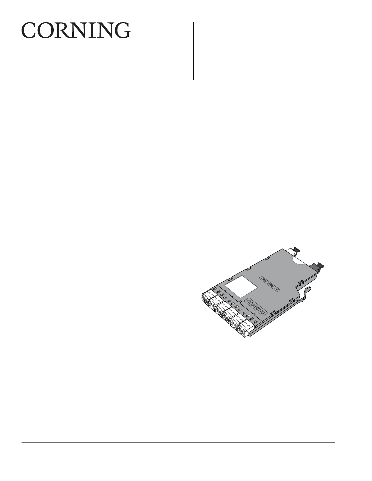
1.1 This procedure describes Pretium EDGE
Tap Modules, which are available for both multimode
and single mode applications. Compatible with all
Pretium EDGE rack-mountable connector housings,
TAP modules have twelve front-mounted shuttered
LC adapters and two MTP®connectors in back
(Figure 1).
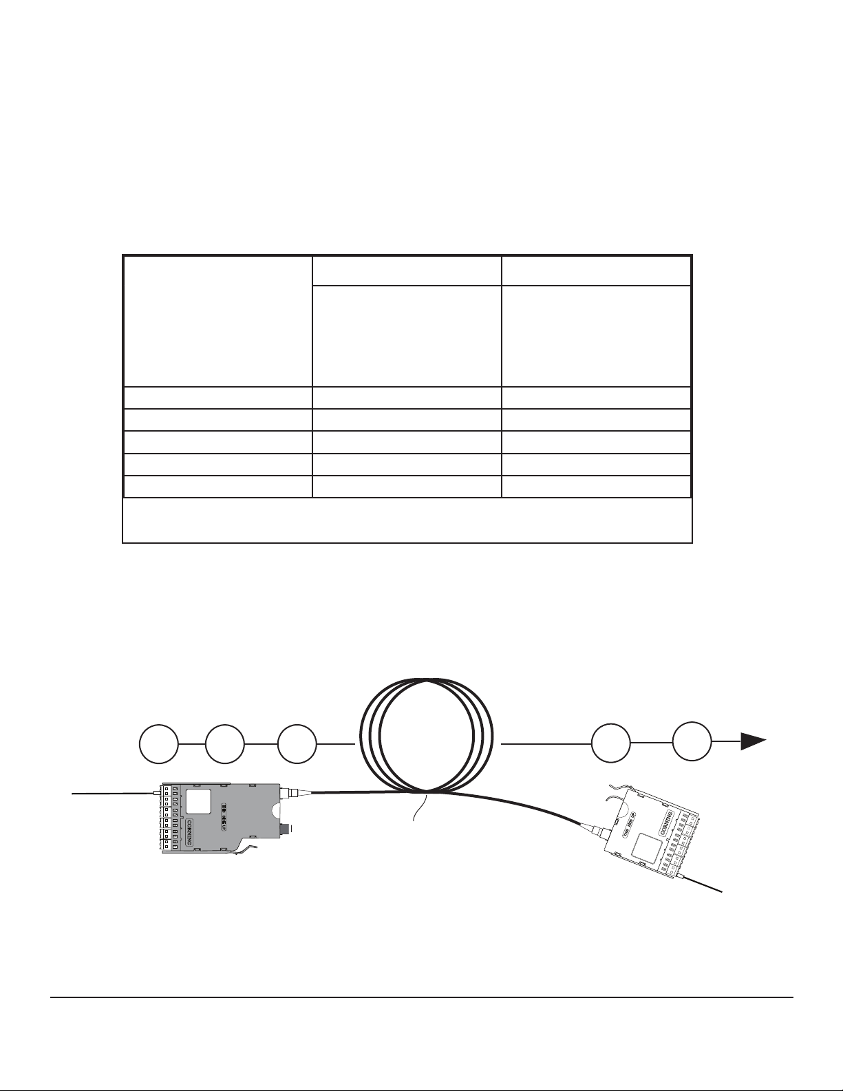
1.2 Themodulecontains12beropticsplitterswhichdividetheincomingopticalsignalsintotwo
outputs,oneforlivelinktrafcandoneformonitoring.Themonitortrafcisroutedviathe“TAP”-labeled
MTPconnectortoamonitoringdevicewhichltersthedataandsendsittovarioussoftwaretoolsfor
analysis, where it is then viewed in application-layer software for security threats, performance issues, or
system optimization.
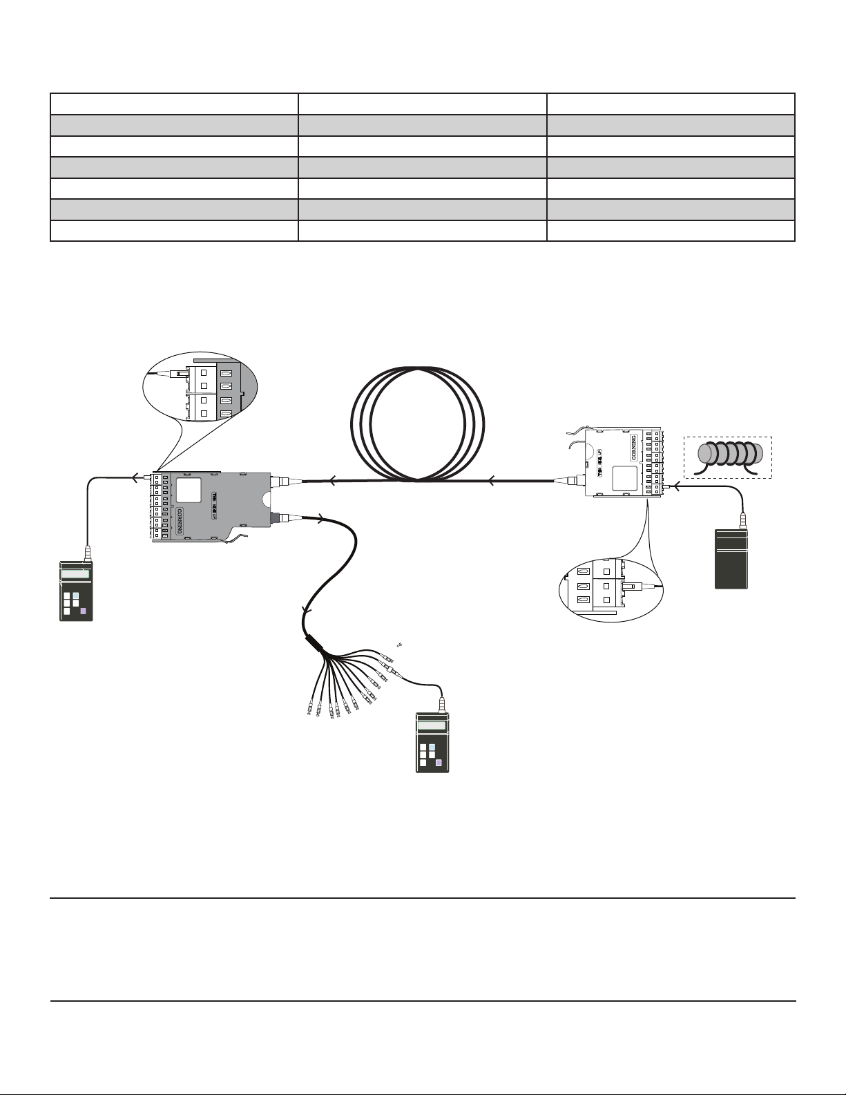
IMPORTANT: Please note that Tap module systems have two outputs for each input, which may
requiretwopowermeters,anddependingonthesystemconguration,possiblyrequireanadditional
craftsperson in another location.
1.4 If this procedure is reissued, a summary of the changes will appear in this paragraph.
2
1
BA
1
4
3
BA
2
6
5
BA
3
8
7
BA
4
10
9
BA
5
12
11
BA
6
VOID
W
A
R
R
A
N
T
Y
Port Tap Module
M
Part Number:
Serial
MADE IN MEXICO
US PATENT NO.
TAP LIVE
Figure 1
HPA-0753
related literature |
SRP-003-794, Pretium EDGE®Solution
SRP-006-136,MultiberConnectorandPortCleaningwiththeTKT-CLEAN-MFC-Mkit
table of contents |
1. General .................................................................................................................................................1
2. Precautions ...........................................................................................................................................2
3. Tools and Materials ...............................................................................................................................2
4. Connector and Adapter Cleaning ..........................................................................................................2
5. Calculating System Loss .Budgets .......................................................................................................3
6. The Functionality of the Tap Module Splitters .......................................................................................5
7. Installing Pretium EDGE Tap Modules ...................................................................................................6
8. Referencing the Test Equipment for a Tap Module ...............................................................................6
9. Testing Pretium EDGETap Modules .....................................................................................................8

STANDARD RECOMMENDED PROCEDURE 003-126 | ISSUE 1 | OCTOBER 2012 | PAGE 2 OF 9
2. Precautions
2.1 Laser Precautions
\WARNING:DONOTusemagniersinthepresenceoflaserlight-diffusedlaserlightcancauseeye
damageoffocusedwithopticalinstruments.Neverlookdirectlyintotheendofaconnectorthatmay
be carrying laser light. Should accidental eye exposure to laser light be suspected, arrange for an eye
examination immediately
2.2 Cable Handling Precautions
NOTE: Fiber optic cable is sensitive to excessive pulling, bending, and crushing forces. Do not bend
cables more sharply than their minimum recommended bend radius. Do not apply more pulling
forcetothecableassemblythanspecied.Donotcrushthecableorallowittokink.Doingsomay
cause damage that can alter the transmission characteristics of the cable; the cable may have to
be replaced.
3. Tools and Materials
3.1 The following tools and materials are required for this procedure:
•Two(2)powermeterswithLCportadapters
•Two(2)LC-LCjumpers
•One(1)SC-LCjumperforthelightsource
•One(1)LC-LCadapter
•Lightsource
•OneMTPtoLCharness
•LCportcleaner(p/nCLEANER-PORT-LC)
•MTPConnectorandPortCleaningTool(p/n2104466-01)
For multimode applications:
•Mandrelwrapsuitableforyourcabletype(availableinp/nOTS-COMBOMAN)
4. Connector and Adapter Cleaning
4.1 Cleaning the LC adapters with an LC port cleaner
before each mating is recommended (Figure 2).
4.2 The use of an MTP Connector and Port Cleaning
Too l to clean MTP connectors and ports before each
mating is recommended (Figure 3).
Figure 2
HPA-0738
Figure 3
HPA-0754

STANDARD RECOMMENDED PROCEDURE 003-126 | ISSUE 1 | OCTOBER 2012 | PAGE 3 OF 9
5. Calculating System Loss Budgets
5.1 This section describes how to calculate the loss budgets of a system using a Pretium EDGE Tap
Module.NotethatyouwillneedtocalculateonelossbudgetfortheLIVEsystem(Figure4)and two different
loss budgets for the Tap output (Figure 5 and 6).
Table 1 indicates the system loss values of the system components:
Table 1
5.2. To calculate the system losses, add the loss values of the components as illustrated in the examples
shown in Figures 4, 5, and 6.
Multimode Fiber Single Mode Fiber
OM4
Ultra-bendable
optimized 50µm
(850 nm)
Bend-improved
single Mode
(1310 nm)
Component Loss, max (dB)1Loss, max (dB)1
MTP® mated pair loss 0.35 0.75
LC mated pair loss 0.15 0.5
Splitter 50/50 (dB) 3.8 3.6
Splitter 30/70 (dB) 6.6 /1.8 6.0 / 2.0
1Insertion loss specifications when mated to other system components of a like
performance specification
B
612
11
A
B
510
9
A
B
48
7
A
B
3
6
Port TapModule
Part Number
Serial
MADEIN MEXICO
TAP LIVE
5
A
B
24
3
A
B
1
2
1
A
W
A
R
R
A
N
T
Y
VOID
Tap Module “A”
Pretium EDGE
Module “B”
HPA-0825
Figure 4
“Near end” “Far end”
Budget loss for a LIVE multimode system using OM4 fiber and 50 /50 splitters:
0.15 0.35 0.35
3.8 0.15
+++
LC mated
pair
LC mated
pair
50/50
splitter
MTP
mated pair
MTP
mated pair
0.15 +3.8 + 0.35 +0.35 + 0.15 = 4.8 dB + fiber loss
Note: Fiber loss
depends on length
of system
B
6
12
11
A
B
5
10
9
A
B
4
8
7
A
B
3
6
PnP Module
Part Number
Serial
MADEIN MEXICO
5
A
B
2
4
3
A
B
1
2
1
A
W
A
R
R
A
N
T
Y
VOID

STANDARD RECOMMENDED PROCEDURE 003-126 | ISSUE 1 | OCTOBER 2012 | PAGE 4 OF 9
B
612
11
A
B
510
9
A
B
48
7
A
B
3
6
Port TapModule
Part Number
Serial
MADEIN MEXICO
TAP LIVE
5
A
B
24
3
A
B
1
2
1
A
W
A
R
R
A
N
T
Y
VOID
Tap port test harness
Tap Module “A”
HPA-0826
Figure 5
“Near end”
Budget loss for a “Near end” Tap port test harness multimode system
using OM4 fiber and 50 /50 splitters:
0.15
0.35
3.8
0.15
+
+
+
LC mated
pair
LC mated
pair
50/50
splitter
MTP
mated pair
0.15 +3.8 + 0.35 + 0.15 = 4.45 dB + fiber loss
Note: Fiber loss
depends on length
of system
B
612
11
A
B
510
9
A
B
48
7
A
B
3
6
Port TapModule
Part Number
Serial
MADEIN MEXICO
TAP LIVE
5
A
B
24
3
A
B
1
2
1
A
W
A
R
R
A
N
T
Y
VOID
Tap Module “A”
Pretium EDGE
Module “B”
HPA-0827 Figure 6
“Far end”
“Near end”
Budget loss for a “Far end” to Tap Port harness multimode system using OM4 fiber and 50 /50 splitters:
0.35 0.35
0.35
3.8 0.15
0.15
+
+
+
++
LC mated
pair
LC mated pair
50/50
splitter
MTP
mated pair
MTP
mated pair
MTP mated pair
Tap port test harenss
0.15 +3.8 + 0.35 + 0.35 + .035 + 0.15 = 5.15 dB + fiber loss
B
6
12
11
A
B
5
10
9
A
B
4
8
7
A
B
3
6
PnP Module
Part Number
Serial
MADEIN MEXICO
5
A
B
2
4
3
A
B
1
2
1
A
W
A
R
R
A
N
T
Y
VOID
Note: Fiber loss
depends on length
of system

STANDARD RECOMMENDED PROCEDURE 003-126 | ISSUE 1 | OCTOBER 2012 | PAGE 5 OF 9
6. The Functionality of the Tap Module Splitters
Directionality
6.1 Insimplestterms,thesplittersinsideaTapmoduleactlikeadividerofaone-waytrafcow–inthis
case, light.
The even-numbered LC connectors in a Tap
module serve only for source inputandtheirtrafcis
splitbetweentheLIVEandTAPoutputs(Figure7,
top).
In the same fashion, the Tap module’s odd-
numbered LC connectors receivelivetrafcfrom
theLIVEMTPinputport.Theinputtrafcfromthe
LIVEinputportissplitbetweentheLIVELCodd
bersandtheMTPTAPport(Figure7,bottom).
Tables 2 and 3 in Section 9 provide a full
representation of the source and output positions
6.2 Tap modules therefore must be tested with directionality in mind. The source must be always connected
to the input of the splitter and the meter must be connected to the output of the splitter. Connecting a source to
the output of a splitter will result in high attenuation.
Wavelength Considerations
6.3 Thesplittersonmultimodemodulesareoptimizedfor850nmVCSEL(Vertical-cavitySurface-emitting
Lasers), thus when testing multimode systems, use only the 850 nm wavelength.
6.4 Single mode systems may be tested at both 1310 and 1550 nm.
B
612
11
A
B
510
9
A
B
48
7
A
B
3
6
TAP LIVE
5
A
B
24
3
A
B
1
2
1
A
W
A
R
R
A
N
T
Y
VOID
Input
into
LC # 2
Live
output
from
LC # 1
LIVE
output
HPA-0755
Tap Output
on MTP Fiber 1 TAP
Output
TAP
Output
B
612
11
A
B
510
9
A
B
48
7
A
B
3
6
TAP LIVE
5
A
B
24
3
A
B
1
2
1
A
W
A
R
R
A
N
T
Y
VOID
LIVE source
Figure 7
Tap Output
on MTP Fiber 2

STANDARD RECOMMENDED PROCEDURE 003-126 | ISSUE 1 | OCTOBER 2012 | PAGE 6 OF 9
7. Installing a Pretium EDGE Tap Module
7.1 PretiumEDGETapmodulesareinstalledjustliketheirnormalPretiumEDGEmodulecounterparts.
Refer to the Installation chapter in SRP-003-794, Pretium EDGE Solution, for complete instructions. This
procedure covers module installation, trouble shooting, and other module-related topics as well.
7.2 Install the Tap module and its Tap MTP harness into your system housing (this procedure illustrates an
MTP to LC harness).
8. Referencing the Test Equipment for a Tap Module
8.1 Start by powering on the source and meter and allowing a minimum of 5 minutes for them to warm up
and stabilize.
For multimode systems: set the unit to the 850 nm wavelength.
For single mode systems: Set the unit to auto-switch between 1310 and 1550 nm wavelengths.
8.2 To reference the source and two meters:
Step 1: Clean and insert the SC-end of the SC
toLCjumper(ReferenceJumperno.1,
or RJ1) into the output of the light
source.
Step 2: Clean and insert the LC end of RJ1
jumperintotheLCportadapterof
Meter no. 1 (M1) (Figure 8).
For multimode only:Wrapthejumper5timesand
secure it in a 25 mm mandrel with tape (standard
50 µm multimode procedure).
Step 3: VerifythatRJ1 is acceptable at your
system’s wavelength(s) and reference
this power to 0.00 dB.
Step 4: Disconnect and move the meter-end LC
of RJ1 to Meter no. 2 (M2) and repeat
step 3. Disconnect M2 after this step.
Step 5: Clean and insert the LC end of RJ1 into an LC adapter.
Light Source
(Tx)
Do NOT
disconnect
Figure 8
HPA-0758
Meter no. 1
(RX)
Meter no. 2
(RX)
M2
0.00
22 mm mandrel wrap for multimode only
Reference
Jumper no.1
RJ1
M1

STANDARD RECOMMENDED PROCEDURE 003-126 | ISSUE 1 | OCTOBER 2012 | PAGE 7 OF 9
Step 6: CleanandinstallanLCtoLCjumper-
ReferenceJumperno.2(RJ2) into M1
and the LC adapter (Figure 9).
Step 7: VerifythattheRJ1/ RJ2 mated pair are
acceptablewithaloss≤0.15dB.
Step 8: Disconnect RJ2’s LC connector from the
LC adapter and protect it with a clean
dust cap until you are ready to start the
system testing.
Step 9: CleanandinstallanLCtoLCjumper-
ReferenceJumperno.3(RJ3) into M2
and the LC adapter (Figure 10).
Step 10: VerifythattheRJ1/RJ3 mated pair are
acceptablewithaloss≤0.15dB.
Step 11: Disconnect RJ1’s LC connector from
the LC adapter and protect it with a
clean dust cap.
Step 12: Leave the LC adapter on the end of RJ3 for the remainder of this procedure since it will be
required for mating to the TAP port test harness.
8.3 Referencing is now complete. Move the Light Source and RJ1 to the front of the Tap module; move
M2, RJ3, and the LC adapter to the end of the Tap harness; and move M1 and RJ2 to the Pretium EDGE
modules at the far end of the system (See Figure 11).
IMPORTANT: Fromthisstepon,doNOTdisconnecttheconnectorsoneithertheLightSourceormeterport
adapters.
Do NOT
disconnect
Do NOT
disconnect
Figure 9
HPA-0759
LC
adapter
0.15 dB
multimode only
RJ1 Reference
Jumper no. 2
RJ2
M1
Light
Source
Do NOT
disconnect
Light Source
M1
Figure 10
HPA-0760
LC
adapter
Dust cap
RJ2
Do NOT
disconnect
0.3 dB
multimode only
RJ 1
RJ3
M2
0.15 dB

STANDARD RECOMMENDED PROCEDURE 003-126 | ISSUE 1 | OCTOBER 2012 | PAGE 8 OF 9
9. Testing Pretium EDGE Tap Modules
9.1 Table 2 provides a complete guide to the testing sequence for testing with the light source at the Tap
module“A”(“Nearend”)andameteratModule“B”,orthe“Farend”ofthesystemshowninFigure11.
Source LC Position at “A' Module “B” LC Position Meter no. 2 -TAP Port Test Harness
A-2 B-1 1
A-4 B-3 3
A-6 B-5 5
A-8 B-7 7
A-10 B-9 9
A-12 B-11 11
Table 2
9.2 To begin testing a Tap module (Figure 11):
Step 1: Install the Light Source/RJ1 LC connector into LC number 2 port of the Tap module.
Step 2: Install RJ2’sLCconnectorintothenumber1portofthePretiumEdgemodule(Module“B”
in Figure 11).
Step 3: Install LC connector number 1 from the Tap port test harness into the LC adapter on the end
of RJ3.
Step 4: Saveorrecordtherstber’smeasurements.Thereadingwillbethetotalsystemloss.
B
612
11
A
B
510
9
A
B
48
7
A
B
3
6
Port TapModule
Part Number
Serial
MADEIN MEXICO
TAP LIVE
5
A
B
24
3
A
B
1
2
1
A
W
A
R
R
A
N
T
Y
VOID
Light
Source
Tap port test harness
Link under test
M1
M2
RJ2
RJ1
Do NOT
disconnect
Do NOT
disconnect
0.00 dB
0.00 dB
Tap Module “A”
Pretium EDGE
Module “B”
B
2
3
B
1
2
1
A
B
24
3
A
B
1
2
1
A
11
1
HPA-0757
Figure 11
multimode only
Do NOT
disconnect
RJ3
“Near end”
“Far end”
B
612
11
A
B
510
9
A
B
48
7
A
B
3
6
PnP Module
Part Number
Serial
MADEIN MEXICO
5
A
B
24
3
A
B
1
2
1
A
W
A
R
R
A
N
T
Y
VOID

STANDARD RECOMMENDED PROCEDURE 003-126 | ISSUE 1 | OCTOBER 2012 | PAGE 9 OF 9
Corning Cable Systems LLC • PO Box 489 • Hickory, NC 28603-0489 USA
1-800-743-2671 • FAX +1-828-325-5060 • International +1-828-901-5000 • http://www.corning.com/cablesystems
CorningCableSystemsreservestherighttoimprove,enhance,andmodifythefeaturesandspecicationsofCorningCableSystems’productswithoutpriornotication.
Pretium EDGE is a registered trademark of Corning Cable Systems Brands, Inc. MTP is a registered trademark of USConec, Ltd. All other trademarks are the properties of
theirrespectiveowners.CorningCableSystemsisISO9001certied.
©2012 Corning Cable Systems. All rights reserved. Published in the USA.
9.3 Table3providesacompleteguidetothetestingsequencefortestingwiththeLightSourceatthe“B”
module(“Farend”)andameteratTapmodule“A”(“Nearend”)ofthesystemasshowninFigure12.
Source LC Position at “B” Meter no.1 LC Position at “A”: Meter no. 2 -TAP Port Test Harness
B-2 A-1 2
B-4 A-3 4
B-6 A-5 6
B-8 A-7 8
B-10 A-9 10
B-12 A-11 12
Table 3
9.4 Totesttheodd-numberedportsatthefrontoftheTapModule,switchthe“Near”and“Far”locationsof
the Light Source/RJ1 and M1/RJ2. At the end of the Tap cable assembly, move the LC adapter on M2/RJ3 to
connector number 2 (Figure 12).
9.5 TocompletethetestingoftherstTapmodule,saveorrecordeachber’smeasurementsasyou
follow the sequence shown in Table 3.
9.6 Repeat the steps in this section on the remaining Tap modules.
B
612
11
A
B
510
9
A
B
48
7
A
B
3
6
Port TapModule
Part Number
Serial
MADEIN MEXICO
TAP LIVE
5
A
B
24
3
A
B
1
2
1
A
W
A
R
R
A
N
T
Y
VOID
Light Source
Tap port test harness
Link under test
RJ2
M1
M2
RJ1
0.00 dB
0.00 dB
B
612
11
A
B
510
9
A
B
48
7
A
B
3
6
PnP Module
Part Number
Serial
MADEIN MEXICO
5
A
B
24
3
A
B
1
2
1
A
W
A
R
R
A
N
T
Y
VOID
Tap Module “A”
Pretium EDGE
Module “B”
B
2
3
B
1
2
1
A
B
24
3
A
B
1
2
1
A
12
RJ3 and adapter
2
HPA-0761
Figure 12
multimode only
“Near end” “Far end”
This manual suits for next models
3
Table of contents
Other CORNING Control Unit manuals
Popular Control Unit manuals by other brands

Acorn Engineering
Acorn Engineering SFST-T-OT-ITG Installation, operation and maintenance instructions

Pololu Corporation
Pololu Corporation A-Star 328PB user guide

HMS
HMS CM CANopen user manual

GF
GF Signet 9950 instruction sheet

GESTRA
GESTRA URS 60 Installation & operating manual

FULLY WIRED ELECTRONICS
FULLY WIRED ELECTRONICS Multi-Logic user manual