manuals.online logo
Brands
  1. Home
  2. •
  3. Brands
  4. •
  5. ADTRAN
  6. •
  7. Control Unit
  8. •
  9. ADTRAN 1200791L1 User manual

ADTRAN 1200791L1 User manual

For more detailed documentation, visit us online at www.adtran.com
NetVanta 950 IAD Octal FXS Access Module P/N 1200791L1
Quick Start Guide
Quick Start Guide, 61200791L1-13C, July 2004 Technical Support 1-888-4ADTRAN (1-888-423-8726) © 2004 ADTRAN, All Rights Reserved
SPECIFICATIONS
Signaling: FXS (Foreign Exchange Station) Loop
Start (LS), Ground Start (GS)
Transmission Level: Transmit Gain: -12dB to +6 dB,
0.1 dB steps
Receive Gain: -12dB to +6 dB,
0.1 dB steps
Loop Statistics: Current: 24mA nominal
Range: 2400ft intra-building
Ringing: 5 REN per port (35 REN maximum for
system), 70 VRMS with 20V DC offset -
open circuit, no load.
Balanced, internal, sinusoidal ring
generation
Impedance: 600Ω, 600Ω+2.16 µF, 9 00Ω,
900Ω+2.16 µF
On-hook battery: 48V nominal
Port Tests: 1 kHz test tone (near-end, far-end
selectable), Ringing, Reverse battery,
Battery, Loopbacks (analog, digital), Tip
open, Transmit signaling bits (0000,
0101, 1010, 1111)
Front Panel LED's: Off: port is on-hook or disabled
Green: port is off-hook
Blinking green: port is ringing
Amber: port is in test
Blinking red: fault condition, port is
disabled for 30 seconds
Environmental: Operating Temperature: 0 ºC to 50 ºC
Storage Temperature: -20 ºC to 70 ºC
Relative Humidity: Up to 95% non-
condensing
Compliance: 60950/UL 60950, Third Edition/CSA
C22.2, No. 60950
FCC Part 15 Class A
INSTALLATION INSTRUCTIONS
1. Remove the locking bar.
2. Remove blank panel if installed.
3. Slide the FXS Module into the access slot until the module is
firmly positioned in the chassis.
Note: Press firmly on the top and bottom of the faceplate to insure
a proper fit.
4. Replace the locking bar and secure with a screwdriver. The
locking bar must be attached at all times.
5. Connect the cables to the associated device(s). Note that the
connections for the voice ports are located on the side of the
chassis.
FXS PINOUT
50-pin female amphenol connectors provide the interconnect wir-
ing for the analog station circuits (FXS ports). Refer to the Net-
vanta 950 IAD Hardware Installation Guide for a detailed
description of the pinout.
COMMANDS
answer-supervision {enable| disable*}
Configures answer supervision for the appropriate voice port(s). Answer supervision
(when the far end answers the call) is indicated by using reverse battery polarity. The
NetVanta responds to LSAS (Line Side Answer Supervision) signaling on the T1 for
FXS answer supervision. LSAS signaling is defined as 0100 (for ESF) or 01/00 (for
D4). The FXS Module reverses battery polarity on tip and ring. The carrier must
configure the network T1 for LSAS (if this is not a point to point T1).
dialtone {enable| disable*}
Configures the FXS Module to provide dialtone to the local FXS interface when
dialtone is not provided by the central office switch. Dialtone is only necessary for
E&M applications and em-conversion must be configured.
* Indicates default values
Quick Start Guide, 61200791L1-13C, July 2004 Technical Support 1-888-4ADTRAN (1-888-423-8726) © 2004 ADTRAN, All Rights Reserved
For more detailed documentation, visit us online at www.adtran.com
NetVanta 950 IAD Octal FXS Access Module P/N 1200791L1
Quick Start Guide
* Indicates default values
COMMANDS (CONTINUED)
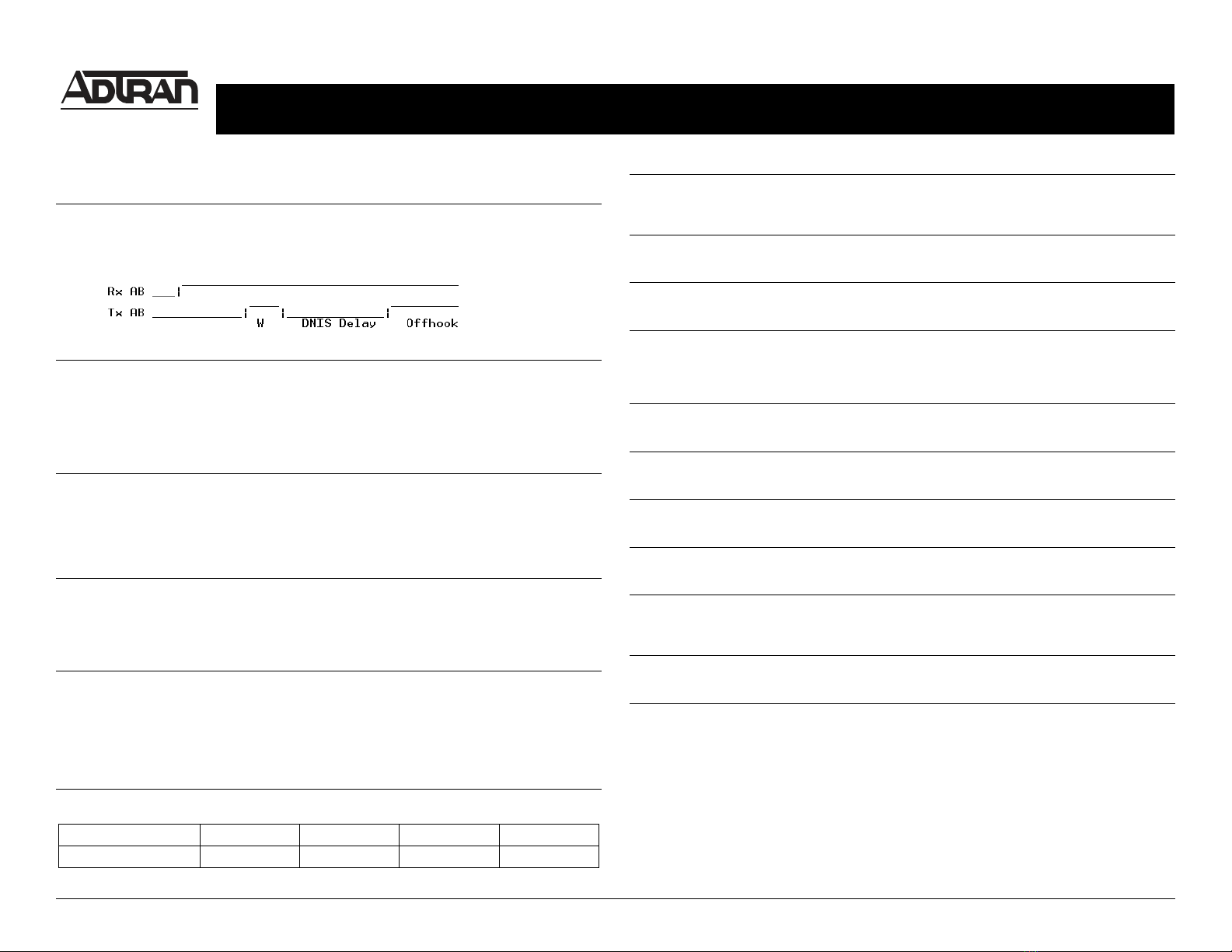
dnis-delay {500 | 1000 | 1500 | 2000 | 2500 | 3000 | 5000}
Defines the time delay after transmitting a wink in response to the 2W going off-hook (after ringing) before
transmitting off-hook towards the T1 interface. The dnis-delay is only valid when em-conversion is
configured for wink. By default, dnis-delay is disabled. The no version of this command disables dnis-
delay.
dnis-wink-timeout {enable*| disable}
When dnis-delay is specified and dnis-wink-timeout is enabled, a wink is returned to the originating
switch after five seconds if the port does not detect an off-hook condition. Disabling this option allows the
FXS port to ring without winking until the call is answered. By default this option is enabled when dnis-delay
is activated.
Note: Trunks can be taken out of service by the central office switch if no wink is received. Use
caution when disabling this option.
em-conversion {immediate | wink}
Specifies the E&M Tandem conversion for the interface. Selecting immediate configures the FXS Module to
transmit digits immediately following an off-hook condition (seizing the line) on an outbound call. Also, no
wink is provided for inbound calls. Selecting wink configures the FXS module to implement a wink process
for inbound calls. When the network seizes the line the FXS module will wink towards the network before
activating the call. For outbound calls the FXS module waits for a wink from the receiving equipment before
activating the call. By default, em-conversion is disabled.
forward-disconnect delay {250 | 500 | 750 | 1000* | 2000}
Specifies the number of milliseconds the FXS Module waits, after initiating a disconnect sequence on the
FXS interface as a result of the remote end terminating the call, before returning to an idle condition. By
default, forward-disconnect delay is 1000 ms. A forward-disconnect delay is only applicable when the
interface is configured for loop start and em-conversion is enabled. The default setting is recommended
initially.
forward-disconnect battery {remove* | reverse}
Specifies the battery behavior during a forward-disconnect situation (where the remote equipment ends the
call). Selecting remove configures the FXS Module to remove battery from the circuit when the remote
equipment ends the call (on-hook condition). Selecting reverse configures the FXS Module to reverse the
battery polarity on the circuit when the remote equipment ends the call. By default, forward-disconnect
battery is set to remove. Setting forward-disconnect battery is only necessary when em-conversion is
configured and a forward-disconnect delay is specified. If configured, the recommended initial setting is
the default.
impedance {600c | 600r* | 900c | 900r}
Sets the AC impedance of the FXS interface.
Option 600c 600r* 900c 900r
Impedance 600Ω + 2.16 µF 600Ω900Ω + 2.16 µF 900Ω
loopback {analog | digital}
Activates a loopback on the FXS Module. Selecting an analog loopback initiates a loop back toward the T1
network side of the connection after passing through analog filters in the voice codec. Selecting a digital
loopback performs the same loopback before passing through analog filters in the voice codec.
ringback {enable | disable*}
Configures the FXS Module to provide ringback to outside callers when not provided by the central office
switch. Ringback is only necessary for E&M applications and em-conversion must be configured.
rx-gain {-12.0 to 6.0} (configure in 0.1 dB increments)
Defines the receive gain characteristics on the FXS interface. Receive gain determines the amplification of
the received signal before transmitting out the FXS interface, By default, the rx-gain is -3.0 dB.
signal {loop-start* | ground-start}
Configures the signaling mode for the FXS interface. Loop-start signaling bridges the tip and ring to
indicate an off-hook (seizing the line) condition. Ground-start signaling applies resistance to the tip
conductor of the circuit to indicate an off-hook condition. This signaling mode must match the configuration
of the network.
test tone {near | far}
Activates a 1 kHz test tone sent towards the FXS interface (near) or out the T1 network interface to the
remote end (far).
test battery
Provides battery on the 2-wire FXS interface. This is helpful when troubleshooting wiring problems with the
FXS equipment.
test reverse-battery
Provides battery with reverse polarity on the 2-wire interface. This is helpful when troubleshooting wiring
problems with the FXS equipment.
test ringing
Activates ringing voltage on the 2-wire interface using a 2 seconds on and 4 seconds off cadence. The no
version of this command removes ringing voltage from the interface.
test signaling-bits {0000 | 0101 | 1010 | 1111}
Sends the specified signaling bits towards the T1. This is helpful when troubleshooting from the far end. Set
the signal bits using this command, then view the status of the line from the remote equipment to verify that
the proper signaling bits are received.
test tip-open
Provides battery on Ring and a high impedance on Tip. This is helpful when troubleshooting problems with
ground start interfaces.
tx-gain {-12.0 to 6.0}
Defines the transmit gain characteristics on the FXS interface. Transmit gain determines the amplification of
the received signal before transmitting from the FXS interface towards the network. By default, the tx-gain
is -6.0 dB.

This manual suits for next models

1

Other ADTRAN Control Unit manuals

ADTRAN Quad E1/PRA User manual

ADTRAN

ADTRAN Quad E1/PRA User manual

ADTRAN Job Aid+ 1442940G1 User manual

ADTRAN

ADTRAN Job Aid+ 1442940G1 User manual

ADTRAN E1 User manual

ADTRAN

ADTRAN E1 User manual

ADTRAN SFP User manual

ADTRAN

ADTRAN SFP User manual

ADTRAN Octal E&M User manual

ADTRAN

ADTRAN Octal E&M User manual

ADTRAN 1200261L1 User manual

ADTRAN

ADTRAN 1200261L1 User manual

ADTRAN jobAid+ SFP+ 11.3 G BIDI 20KM User manual

ADTRAN

ADTRAN jobAid+ SFP+ 11.3 G BIDI 20KM User manual

ADTRAN Total Access 300 Series User manual

ADTRAN

ADTRAN Total Access 300 Series User manual

ADTRAN Total Access 300 Series User manual

ADTRAN

ADTRAN Total Access 300 Series User manual

ADTRAN Total Access 300 User manual

ADTRAN

ADTRAN Total Access 300 User manual

ADTRAN Job Aid+ 1442982G7C User manual

ADTRAN

ADTRAN Job Aid+ 1442982G7C User manual

ADTRAN Job Aid+ 1442971GX User manual

ADTRAN

ADTRAN Job Aid+ 1442971GX User manual

ADTRAN Job Aid+ 1442704PG2 User manual

ADTRAN

ADTRAN Job Aid+ 1442704PG2 User manual

ADTRAN OC-3 User manual

ADTRAN

ADTRAN OC-3 User manual

ADTRAN NetVanta Octal T1/E1 Wide Module User manual

ADTRAN

ADTRAN NetVanta Octal T1/E1 Wide Module User manual

ADTRAN Total Access 351 Series User manual

ADTRAN

ADTRAN Total Access 351 Series User manual

ADTRAN FXS+ Quad User manual

ADTRAN

ADTRAN FXS+ Quad User manual

ADTRAN NetVanta SHDSL User manual

ADTRAN

ADTRAN NetVanta SHDSL User manual

ADTRAN SFP GPON ONU User manual

ADTRAN

ADTRAN SFP GPON ONU User manual

ADTRAN ATLAS 800 Series Module QUAD E1 User manual

ADTRAN

ADTRAN ATLAS 800 Series Module QUAD E1 User manual

ADTRAN Job Aid+ 1442981G8C User manual

ADTRAN

ADTRAN Job Aid+ 1442981G8C User manual

ADTRAN Job Aid+ 1442707G3 User manual

ADTRAN

ADTRAN Job Aid+ 1442707G3 User manual

ADTRAN E220 HFAC HDSL Instruction Manual

ADTRAN

ADTRAN E220 HFAC HDSL Instruction Manual

ADTRAN Total Access 1500 Instruction Manual

ADTRAN

ADTRAN Total Access 1500 Instruction Manual

Popular Control Unit manuals by other brands

Lozar TM73 TWIN user manual

Lozar

Lozar TM73 TWIN user manual

DynaQuip WaterCop Pro WPACT12V quick start guide

DynaQuip

DynaQuip WaterCop Pro WPACT12V quick start guide

Danze D5609 Series installation instructions

Danze

Danze D5609 Series installation instructions

Armstrong A Series instructions

Armstrong

Armstrong A Series instructions

Omron G9SX Series manual

Omron

Omron G9SX Series manual

Allmatic SCOR.AS manual

Allmatic

Allmatic SCOR.AS manual

V2 CITY11 manual

V2

V2 CITY11 manual

Siemens ECOFAST 3RK1911-4AA Series operating instructions

Siemens

Siemens ECOFAST 3RK1911-4AA Series operating instructions

Trumbull 367-1414 Installation, operation and maintenance manual

Trumbull

Trumbull 367-1414 Installation, operation and maintenance manual

Truth Hardware Marvel Programming manual

Truth Hardware

Truth Hardware Marvel Programming manual

KMC Controls HPO-9001 installation guide

KMC Controls

KMC Controls HPO-9001 installation guide

Webasto MultiControl installation instructions

Webasto

Webasto MultiControl installation instructions

Bluewin ACB225 Installation

Bluewin

Bluewin ACB225 Installation

Advanced Energy Thyro-PX Anybus Modbus TCP Guide

Advanced Energy

Advanced Energy Thyro-PX Anybus Modbus TCP Guide

National Instruments PXIe-4340 user manual

National Instruments

National Instruments PXIe-4340 user manual

Honeywell Class 500 installation instructions

Honeywell

Honeywell Class 500 installation instructions

Comelit VEDOGSM4G Technical manual

Comelit

Comelit VEDOGSM4G Technical manual

Numato AD9763 user guide

Numato

Numato AD9763 user guide

manuals.online logo
manuals.online logoBrands
  • About & Mission
  • Contact us
  • Privacy Policy
  • Terms and Conditions

Copyright 2025 Manuals.Online. All Rights Reserved.