Watermark SS-TH1000 User manual

INSTALLTION FOR
THERMOSTATIC VALVES
P a g e | 1
SS-TH1000
½” THERMOSTATIC VALVE
SS-TH3000
¾” THERMOSTATIC VALVE
SS-TH2000
½” THERMOSTATIC VALVE WITH
BUILT IN VOLUME CONTROL
SS-TH4000
¾” THERMOSTATIC VALVE WITH
BUILT IN VOLUME CONTROL
Features:
Ability to pre-select water temperature –thus conserving water
Compensates for water pressure fluctuations preventing scalding
Safety button at 100°F prevents accidental scalding
High flow rates allow for multiple shower applications
Listed by IAPMO, CSA, NSF, and other municipalities
Specifications:
oOperating pressure is 20 PSI to 72 PSI
oWhen pressure is higher than 72 PSI a pressure reducer (fitted before the valve) is required.
oTemperature range is 50°F to 180°F
oRecommended setting is 29 PSI and 149°F
Note:
DO NOT USE PLUMBER’S PUTTY ON ANY OF THE BRASS COMPONENTS
This will cause the finish to tarnish and void the warranty. A non-corrosive Alkoxy Silicone is
recommended.
DURING SWEATING OF LINES DO NOT OVERHEAT CASTING
Overheating may cause damage to internal mechanism and void the manufacturer’s warranty as
well as increase the risk of scalding.
COPPER ADAPTORS MAY BE REQUIRED TO COMPLETE YOUR INSTALLATION
Shipping weight: 4 lb (SS-TH1000/3000) or 5 lb (SS-TH2000/4000)
Shipping dimension: 7”x7”x3.5”(SS-TH1000/3000) or 8”x7.5”x6”(SS-TH2000/4000)
Note:
Separate wall stops/shut off valves/volume controls (SS-TS150 or SS-TS200) may be needed in
conjunction with this valve. A thermostatic valve’s only function is to mix temperature.
Diagram 1: Flow Rate Vs. Pressure
Rev. 10/17

INSTALLTION FOR
THERMOSTATIC VALVES
P a g e | 2
Valve Installation
1. Flush the lines of all dirt and debris. Failure to completely flush the lines will cause valve failure and
will void the manufacturer’s warranty.
2. Fit the valve on the wall without removing the plastic cover on the control spindle. Turning the
control spindle will change the temperature setting which is pre-calibrated at the factory.
3. Connect the hot water supply to the left inlet of the valve (hot marked with red paint) and cold
supply to the right inlet (cold marked with blue paint).
4. Use the Plastic Mudguard (1) (part of the package) to position the Valve (2) in the wall. This is done
by checking the markings on the mudguard for the minimum/ maximum settings which are 1 1/2” to
2 1/8”from the center of the valve inlets to the finished wall.
Diagram 2: Plastic Mudguard
5. Connect the outlet pipe. Install tile stops/volume controls between the thermostatic valve and each
device to be operated. See Diagram 8 for sample installations.
NOTE: Water temperature from the bottom outlet will be slightly colder than water
temperature from the top outlet.
Trim Installation (see Diagram 4)
1. Screw Temperature Control Dome (1) and Volume Control Dome (9) (where applicable) onto valve.
NOTE: Temperature Control Dome (1) has a larger opening than Volume Control Dome (9).
2. Slide the Thermostatic Face Plate (3) onto the valve by sliding over the Temperature Control Dome
(1) and Volume Control Dome (9) (where applicable) and hold in place.
3. Screw Thermostatic Face Plate Lock Ring(s) (4) into Dome Sleeve(s) (2).
4. Lock the Thermostatic Face Plate (3) securely against the wall by screwing Dome Sleeve(s) (2) with
Thermostatic Face Plate Lock Ring(s) (4) onto Temperature Control Dome (1) and Volume Control
Dome (9) (where applicable).
5. Ensure Temperature Limit Stop Ring (5) is installed with red dot at 12 o’clock position.
6. Install Temperature Control Post (6) onto valve with push button at 12 o’clock position and install
Temperature Control Handle (8) onto Temperature Control Post (6). Install Volume Control Post
(10)onto valve and install Volume Control Handle (12) onto Volume Control Post (10).
NOTE: Some heavier lever handles come with friction washers to prevent rotation due to gravity.
The thinner of these washers is for use with this valve when needed (see Diagram 3).

INSTALLTION FOR
THERMOSTATIC VALVES
P a g e | 3
Diagram 3
Diagram 4: Representative Trim
SS-TH1000 or SS-TH3000
SS-TH2000 or SS-TH4000
Parts Checklist –SS-TH1000 or SS-TH3000 (SS-TH2000 or SS-TH4000)
Carefully remove all parts from the box. The following parts should be included.
Item #
Description
Qty.
Item #
Description
Qty.
1
Temperature Control Dome
1
7
Temperature Control Screw
1
2
Dome Sleeve (raw brass)
1 (2)
8
Temperature Control Handle
1
3
Face Plate
1
9
Volume Control Dome
0 (1)
4
Lock Ring
1 (2)
10
Volume Control Post
0 (1)
5
Temperature Limit Stop Ring
1
11
Volume Control Screw
0 (1)
6
Temperature Control Post
1
12
Volume Control Handle
0 (1)

INSTALLTION FOR
THERMOSTATIC VALVES
P a g e | 4
Temperature Setting
The delivered temperature of the valve varies depending on the temperature of the supplied hot water. The
valve is factory set at a supplied temperature of 149°F under balanced pressures. Depending on your
preferred hot water temperature setting, it may be necessary to adjust the calibrations of the valve. The
limit override button is preset at 100°F and can be adjusted as described below.
1. Select 100°F on the control handle.
2. Without turning the handle, remove the handle by unscrewing the screw and pulling off (screw may
be concealed and/or fastened with set screws).
3. Use a thermometer to check the delivered temperature on one of the outlets.
4. Adjust water temperature to 100°F by hand turning the cartridge stem slowly left or right.
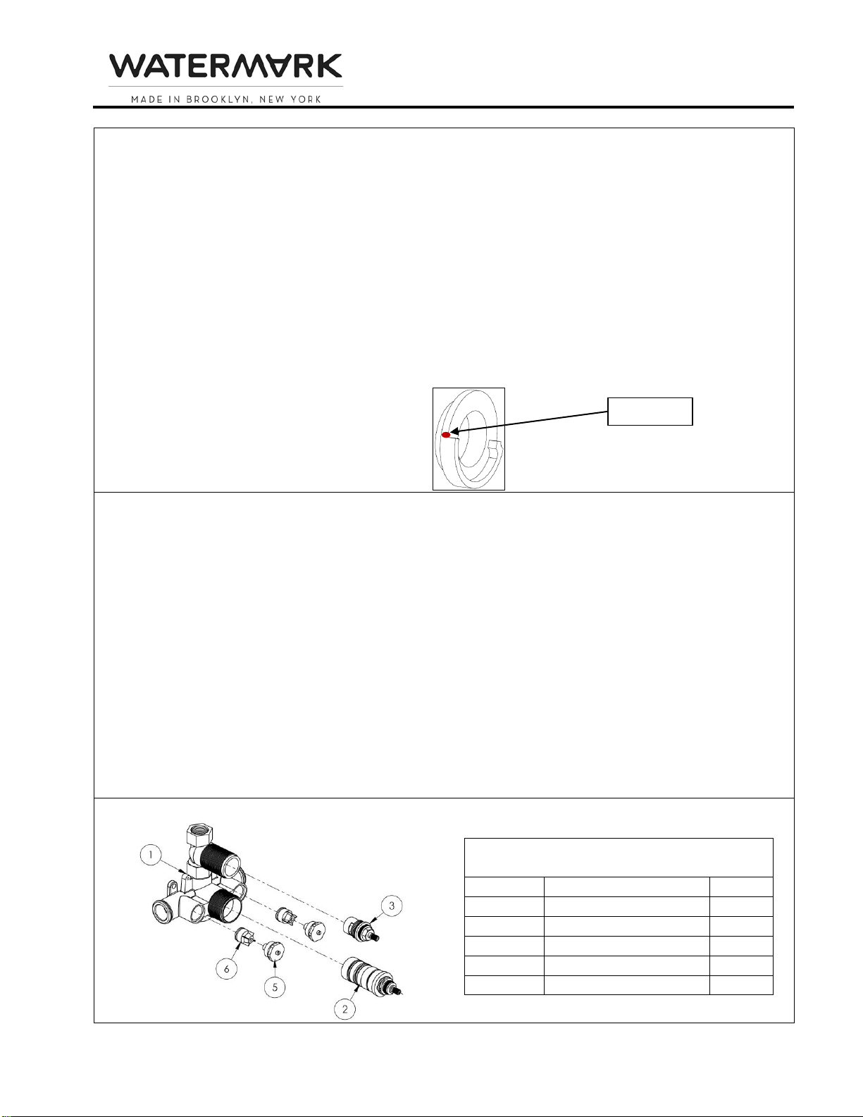
5. Ensure that the temperature limit stop-ring is installed with red dot at 12 o’clock position.
6. Install the handle back on the valve with the push button at the 12 o’clock position.
Diagram 5: Temperature Limit Stop Ring
Removal and Maintenance of Cartridge(s) (see Diagram 6)
This thermostatic cartridge has screens to prevent dirt and unwanted particles from damaging the valve.
Clogged screens can cause reduced flow and inefficient temperature mixture by the valve. You can easily
clean the screens by following the instructions below.
1. Remove the trim by following the Trim Installation steps above in reverse.
2. Shut off the water inlets by tightening the two screws at the two check stop valves.
3. Unscrew Thermostatic Cartridge (2) with a 30mm socket wrench or other adjustable wrench in a
counter-clockwise direction and gently pull out.
4. Clean the screens and rinse with water. If necessary, soak in a 50/50 mix of white vinegar/ water or
a de-scaling agent until all dirt is dissolved. Grease the o-rings with a silicone based grease and wipe
the housing with a wet cloth before reassembling.
5. Reassemble the valve by reversing these instructions. Make sure the red dot on the temperature
limit stop ring and push button on the handle are both aligned in the 12 o’clock position.
NOTE: Temperature may need to be reset as per instructions above.
NOTE: To prevent the handle from accumulating mineral build up which can cause the handle to “lock
up,”the handle must be turned on an occasional basis.
Diagram 6: Cartridge Removal/Check Valve Removal
Parts List SS-TH1000 or SS-TH3000
(SS-TH2000 or SS-TH4000)
Item #
Description
Qty.
1
Valve Body
1
2
Thermostatic Cartridge
1
3
Volume Cartridge
0 (1)
5
Service Stop Nut
2
6
Check Valve
2
RED DOT

INSTALLTION FOR
THERMOSTATIC VALVES
P a g e | 5
Troubleshooting
Malfunction
Cause
Remedy
Cannot regulate temperature
Dirt in check valves
Water supply reversed
Valve installed upside down
Remove and clean check valves
Reverse hot and cold supply lines
Reverse valve
Hot and cold water do not mix
Lack of water pressure at one
of the inlets
Blocked shower head
Correct water pressure at source
Remove shower head and clean debris.
If necessary, soak in a 50/50 mix of
white vinegar/ water or a de-scaling
agent until all dirt is dissolved.
Water not hot enough /
Water too hot
Debris in check valves
Valve not properly calibrated
Water heater setting incorrect
Remove and clean check valves
Calibrate valve following instructions on
page 4
Adjust water heater temperature setting
Temperature selected on
handle is different than actual
water temperature
Debris in check valves
Valve not properly calibrated
Uneven hot & cold water
pressure
Remove and clean check valves
Calibrate valve following instructions on
previous page
Check and adjust water pressure for
both hot & cold supply lines
Handle does not turn
Mineral build up
Remove and clean cartridge following
instructions above
Low water pressure
Low water pressure
Debris in cartridge
Debris in check valves
Blocked shower head
Check and adjust water pressure at
source
Remove and clean cartridge following
instructions above
Remove and clean check valves
Remove shower head and clean debris.
If necessary, soak in a 50/50 mix of
white vinegar/ water or a de-scaling
agent until all dirt is dissolved.
Leaking shower head
Fault cartridge in wall stop/
volume control
Repair or replace cartridge in wall stop/
volume control
Valve body too deep into wall
The measured rough in or
finished wall surface is incorrect
Install an extension kit:
SS-EXT41 for SS-TH1000 or SS-TH3000
SS-EXT51 for SS-TH2000 or SS-TH4000

INSTALLTION FOR
THERMOSTATIC VALVES
Thermostatic Valves P a g e | 6
Diagram 7 –Dimensional Drawings
Diagram 8: Sample Layouts
This manual suits for next models
3
Table of contents
Other Watermark Control Unit manuals
Popular Control Unit manuals by other brands

VAT
VAT 192 Series Installation, operating, & maintenance instructions

BNC
BNC 106C instruction manual

Sharp
Sharp ND-AK270 installation manual

Hirschmann
Hirschmann PRS 80 Operators & service manual

damixa
damixa 48408 Installation instruction

Smitec
Smitec HELCON 10 Series Installation, use & maintenance manual

Danfoss
Danfoss GBC 6s H installation guide

FAAC
FAAC 578D manual

Larson Electronics
Larson Electronics LM-SYM-XX-CTRL-R1 instruction manual

Mouser Electronics
Mouser Electronics TMS320C5515 Quick start installation guide

Becker
Becker Beck-O-Tronic 5 Assembly and operating instructions

ACS
ACS ACM39U-Y user manual