manuals.online logo
Brands
  1. Home
  2. •
  3. Brands
  4. •
  5. Lutron Electronics
  6. •
  7. Control System
  8. •
  9. Lutron Electronics RRD-6CL-WH User manual

Lutron Electronics RRD-6CL-WH User manual

Switch
English
Please read before installing.
Use our mobile friendly self-paced
installation tool:
www.lutron.com/wiringwizard
Find more product information:
www.lutron.com/support
- Videos
- Frequently Asked Questions
- Online Chat (8 am – 5 pm EST)
Call us:
U.S.A. | Canada | Caribbean
1.844.LUTRON1 (588.7661) (24/7)
Mexico
+1.888.235.2910
Others
+1.610.282.3800
www.lutron.com/support
Limited Warranty:
www.lutron.com/TechnicalDocumentLibrary/Warranty.pdf
For FCC/IC information:
Please visit: www.lutron.com/fcc-ic
Lutron, Claro, and Satin Colors are trademarks or registered trademarks of
Lutron Electronics Co., Inc. in the US and/or other countries.
All product names, logos, and brands are property of their
respective owners.
©2021 Lutron Electronics Co., Inc.
ON
OFF
WARNING: ELECTRIC SHOCK HAZARD.
May result in Serious Injury or Death. Turn off
power at circuit breaker or fuse before installing.
1Turn power OFF at circuit breaker 2Determine wiring configuration
Ground wire
(bare or green)
IMPORTANT
Ground wire
(bare or green) Ground wire
(bare or green)
Green wire Green wire
Switch
Brass
Black
Blue
Marked wire Marked
wire
Companion Switch
For lights switched from one location:
2A
OR
For lights switched from two locations:
NOTE: Only one switch can be used per circuit.
NOTE: Switch must be wired on the load side. Connect Neutral to the switch. Up to four companion switches may be used.
For additional wiring assistance go to www.lutron.com/wiringwizard
2B
Fully wrap the wires around the screw and tighten (A), or
strip insulated wires to 1/2 in (13 mm) and insert into the
push-in terminals (B). Solid copper wire only.
1/2 in
(13 mm)
OR
Different-
colored
screw
Ground wire
(bare or green)
IMPORTANT:
Tag or mark the
common wire on both
existing devices. This
is usually connected to
a darker (or different)
colored screw than the
others. This does NOT
include the ground
screw.
(continued on next page)
Switch
120 V~50/60 Hz
Companion Switch (for 3-way wiring)
120 V~50/ 60 Hz 8.3 A
Lighting Load – 8 A
Motor Load – 1/4 HP 5.8 A
1. CAUTION: Use only with permanently installed fixtures with screw-in LED,
self-ballasted compact fluorescent, halogen, or incandescent lamps. Use only to
control the primary side of permanently installed transformer supplied
low-voltage lighting, or in combination with incandescent lamps. To reduce the
risk of overheating and possible damage to other equipment DO NOT use to
control receptacles.
2. Neutral is required for all load types.
3. Install in accordance with all national and local electrical codes.
4. When no “grounding means” exist within the wallbox, the NEC®2011, Article
404.9 allows a switch without a grounding connection to be installed as a
replacement, as long as a plastic, noncombustible wallplate is used. For this
type of installation, twist a wire connector onto the green ground wire or remove
the green ground wire on the switch and use an appropriate wallplate such as
Claro or Satin Colors series wallplates by Lutron.
5. Protect the switch from dust and dirt when painting or spackling the wall.
6. This switch is not compatible with standard 3-way or 4-way switches. Use only
with Lutron companion switches listed above.
7. In any 3-way / 4-way circuit use only one switch with up to
4 companion switches.
8. Maximum wire length between the switch and the farthest companion switch is
150 ft (45 m).
9. Operate between 32 °F and 104 °F (0 °C and 40 °C).
10. It is normal for the switches to feel warm to the touch during operation.
11. Clean the switch with a soft damp cloth only. Do not use any chemical cleaners.
For disinfecting, please refer to App Note #758 (048758), “Cleaning
Recommendations for Lutron Products” at www.lutron.com.
12. For indoor use only.
A
Ground wire
(bare or green)
Brass
Green wire
Switch
Neutral
Load/Light
Line/Hot
Brass
120 V~
50 / 60 Hz
Neutral
Blue
Black
Silver
Green
Ground
Switch
Line / Hot
Load
** For more information please go to www.lutron.com/wiringwizard
Brass
120 V~
50 / 60 Hz
Brass
Blue Blue
Black Black
Silver
Green
Green
Ground
Line / Hot
Ground
Companion Switch
Switch
Load
Neutral
A
English
Help
Line /Hot
To breaker
Load
To Light/Motor
Neutral
Brass
120 V~
50 / 60 Hz
Brass
Blue Blue
Black Black
Silver
Green
Green
Ground
Line / Hot
Ground
Switch
Companion Switch
Load
Neutral
A
NOTE: DO NOT install switch on the line side.
NOTE: Switch MUST be on the load side.
BlueBrass
Black
A
Silver
Black
Silver
Blue
OR
14 AWG ONLY
(1.5 mm2)
B
A
5 in-lbs (0,55 N
•
m)
12 / 14 AWG
(2.5 – 1.5 mm2)
ON
OFF
4Turn power ON at circuit breaker
3Mount all devices using the provided
screws and attach wallplate
For lights switched from three or more locations:
2C
Companion Switch
Brass Blue
Black
Ground wire
(bare or green) Green wire
Different-
colored
screw
Ground wire
(bare or green)
IMPORTANT:
Tag or mark the
common wire on
existing 3-way
devices. This is usually
connected to a darker
(or different) colored
screw than the others.
This does NOT include
the ground screw.
Green wire
Companion Switch
Marked
wire
Ground wire
(bare or green)
NOTE: Only one switch can be used per circuit.
A
B
Hot
A
C
D
B
Switch
Marked
wire
Ground wire
(bare or green) Green wire
Brass
Neutral
Load
To light/motor
Line/Hot
To breaker
B
B
A
A
A
NOTE: Switch must be wired on the load side. Neutral has been excluded from this diagram for clarity. Connect Neutral to the switch.
Up to four companion switches may be used. For additional wiring assistance go to www.lutron.com/wiringwizard
Companion Switch Companion Switch Switch
Blue
Silver
BlueBlue
BlackBlackBlack
Line / Hot
GreenGreenGreen
BrassBrassBrass
GroundGroundGround
Neutral
120 V~
50 / 60 Hz
Load
DC
D
C
Brass Blue
Black
Blue
Black
Silver
This device complies with part 15 of the FCC Rules and Industry Canada license-exempt RSS standard(s). Operation is subject to the following two conditions:
(1) This device may not cause interference, and
(2) This device must accept any interference, including interference that may cause undesired operation. Modifications not expressly approved by Lutron ElectronicsCo., Inc. could void the user’s authority to operate
this equipment.
NOTE: This equipment has been tested and found to comply with the limits for a Class B digital device, pursuant to part 15 of the FCC Rules. These limits are designed to provide reasonable protection against harmful
interference in a residential installation. This equipment generates, uses and can radiate radio frequency energy and, if not installed and used in accordance with the instructions, may cause harmful interference to radio
communications. However, there is no guarantee that interference will not occur in a particular installation. If this equipment does cause harmful interference to radio or television reception, which can be determined by
turning the equipment off and on, the user is encouraged to try to correct the interference by one or more of the following measures:
• Reorient or relocate the receiving antenna
• Increase the separation between the equipment and receiver
• Connect the equipment into an outlet on a circuit different from that to which the receiver is connected
• Consult the dealer or an experienced radio/TV technician for help.
This equipment complies with FCC/ISED radiation exposure limits set forth for an uncontrolled environment. The user should avoid prolonged exposure within 7.9 in (20 cm) of the antenna, which may exceed FCC/ISED
radio frequency exposure limits.
This Class B digital apparatus complies with Canadian ICES-003.
FCC / IC / IFT Information

Other Lutron Electronics Control System manuals

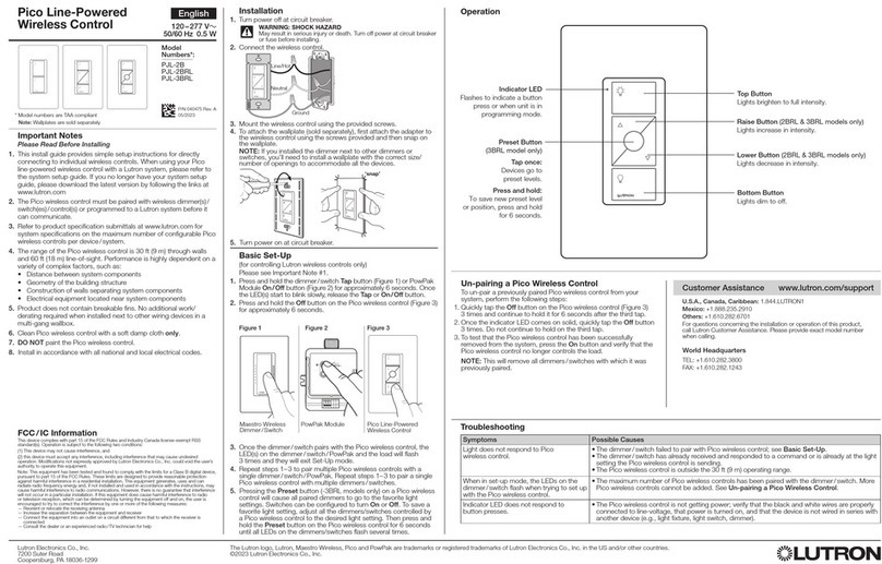
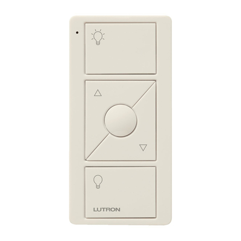
Lutron Electronics Pico PJL-2B User manual

Lutron Electronics

Lutron Electronics Pico PJL-2B User manual

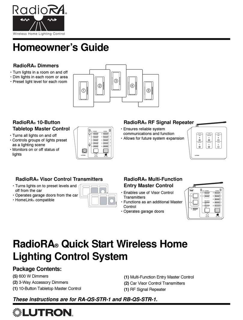
Lutron Electronics RadioRA-SR User manual

Lutron Electronics

Lutron Electronics RadioRA-SR User manual

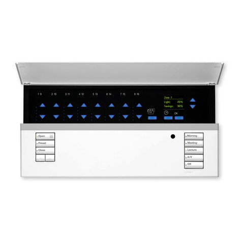
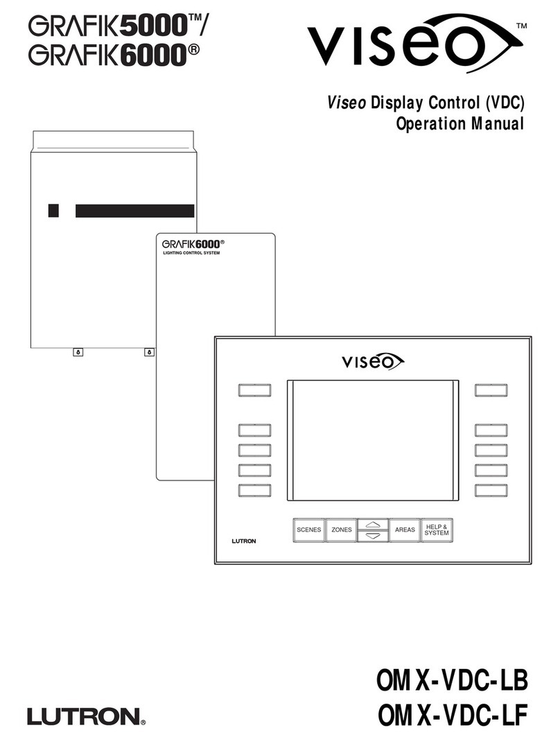
Lutron Electronics VISEO GRAFIK5000 User manual

Lutron Electronics

Lutron Electronics VISEO GRAFIK5000 User manual

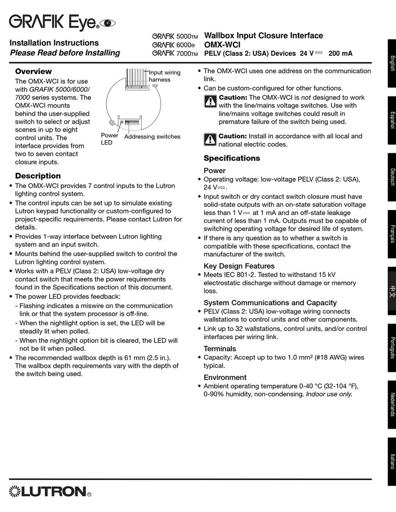
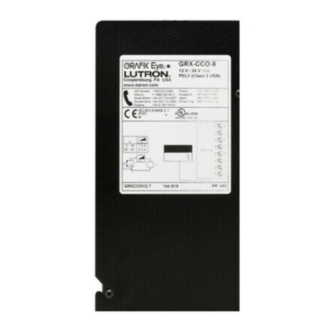
Lutron Electronics Grafik Eye GRX-CCO-8 User manual

Lutron Electronics

Lutron Electronics Grafik Eye GRX-CCO-8 User manual

Lutron Electronics RadioRA 2 User manual

Lutron Electronics

Lutron Electronics RadioRA 2 User manual

Lutron Electronics GRAFIK Eye QSG-3PCE Operating instructions

Lutron Electronics

Lutron Electronics GRAFIK Eye QSG-3PCE Operating instructions

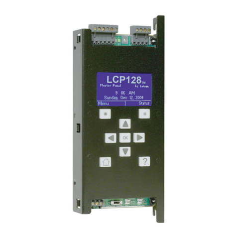
Lutron Electronics LCP128 User manual

Lutron Electronics

Lutron Electronics LCP128 User manual

Lutron Electronics myRoom User manual

Lutron Electronics

Lutron Electronics myRoom User manual

Lutron Electronics RadioRA Assembly instructions

Lutron Electronics

Lutron Electronics RadioRA Assembly instructions

Lutron Electronics GRAFIK 6000 User manual

Lutron Electronics

Lutron Electronics GRAFIK 6000 User manual

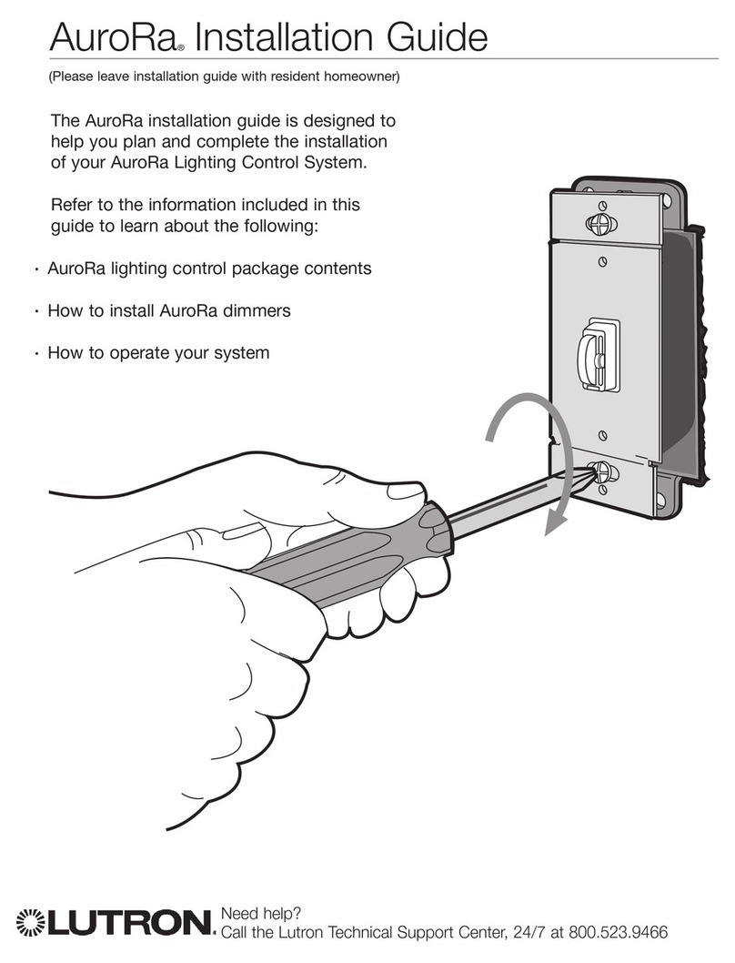
Lutron Electronics AuroRa User manual

Lutron Electronics

Lutron Electronics AuroRa User manual

Lutron Electronics Grafik Eye User manual

Lutron Electronics

Lutron Electronics Grafik Eye User manual

Lutron Electronics RadioRA User manual

Lutron Electronics

Lutron Electronics RadioRA User manual

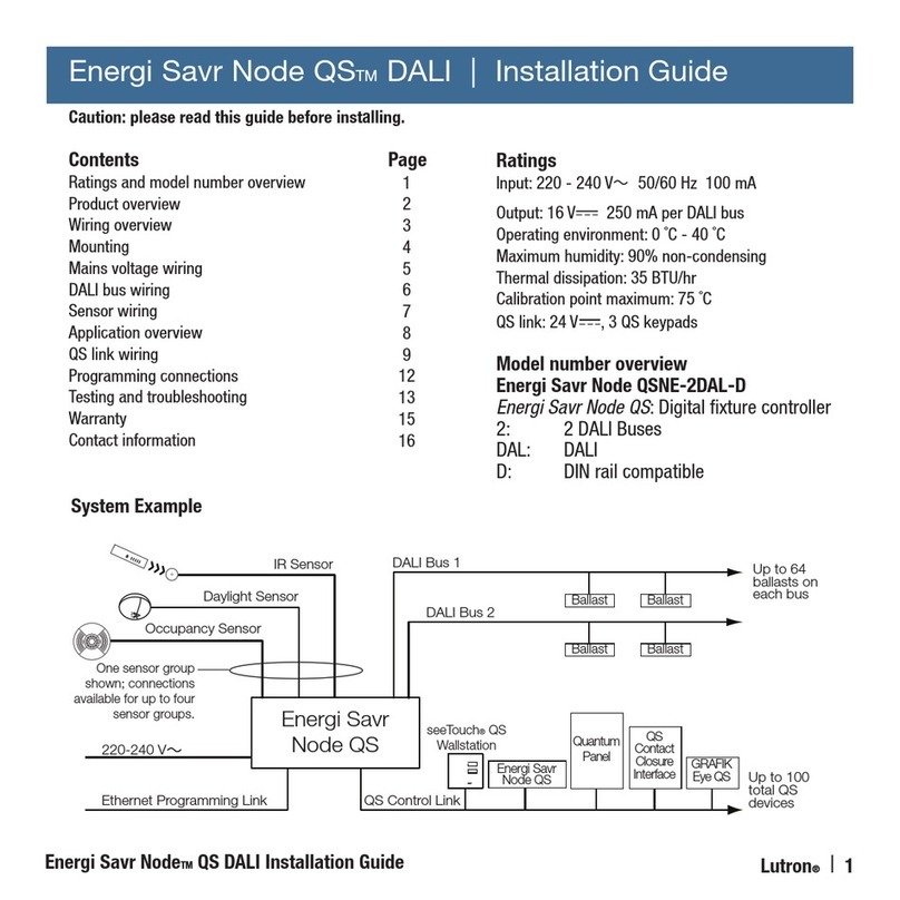
Lutron Electronics Energi Savr Node QS DALI User manual

Lutron Electronics

Lutron Electronics Energi Savr Node QS DALI User manual

Lutron Electronics homeworks qs User manual

Lutron Electronics

Lutron Electronics homeworks qs User manual

Lutron Electronics PJ2-3BRL User manual

Lutron Electronics

Lutron Electronics PJ2-3BRL User manual

Lutron Electronics Architrave GRAFIK5000 User manual

Lutron Electronics

Lutron Electronics Architrave GRAFIK5000 User manual

Lutron Electronics Stanza User manual

Lutron Electronics

Lutron Electronics Stanza User manual

Lutron Electronics RadioRA 2 User manual

Lutron Electronics

Lutron Electronics RadioRA 2 User manual

Lutron Electronics RadioRA 2 User manual

Lutron Electronics

Lutron Electronics RadioRA 2 User manual

Popular Control System manuals by other brands

JEAN LUTZ TARALOG instruction manual

JEAN LUTZ

JEAN LUTZ TARALOG instruction manual

SALUPO MULTIPLUS 1 SA684 Series Instruction and installation manual

SALUPO

SALUPO MULTIPLUS 1 SA684 Series Instruction and installation manual

BFT PHP ADA installation manual

BFT

BFT PHP ADA installation manual

Siemens DMS8000 Connectivity guide

Siemens

Siemens DMS8000 Connectivity guide

LEGRAND QMotion QzHub3 Guide

LEGRAND

LEGRAND QMotion QzHub3 Guide

ProFire PF3100 FARC user guide

ProFire

ProFire PF3100 FARC user guide

Siku CONTROL32 operating instructions

Siku

Siku CONTROL32 operating instructions

Uni-bond E-F291-2 user manual

Uni-bond

Uni-bond E-F291-2 user manual

Crestron FlipTop FT2 Series quick start

Crestron

Crestron FlipTop FT2 Series quick start

Honeywell Tradeline H1008D installation instructions

Honeywell

Honeywell Tradeline H1008D installation instructions

Ruida Technology RDC6445G manual

Ruida Technology

Ruida Technology RDC6445G manual

Veeder-Root TLS-300 Operator's quick guide

Veeder-Root

Veeder-Root TLS-300 Operator's quick guide

Alpha Communications TekTone CM800 Installation & operating instructions

Alpha Communications

Alpha Communications TekTone CM800 Installation & operating instructions

Beninca DA.24V manual

Beninca

Beninca DA.24V manual

Minka Group minkaAire AireControl WC1000 instructions

Minka Group

Minka Group minkaAire AireControl WC1000 instructions

FRC Turbofoam TFC100 user manual

FRC

FRC Turbofoam TFC100 user manual

IAI RCON-LC instruction manual

IAI

IAI RCON-LC instruction manual

JUMO mTRON T operating manual

JUMO

JUMO mTRON T operating manual

manuals.online logo
manuals.online logoBrands
  • About & Mission
  • Contact us
  • Privacy Policy
  • Terms and Conditions

Copyright 2025 Manuals.Online. All Rights Reserved.