Cortex PR-4 Space Saver Folding Squat Power Rack User manual
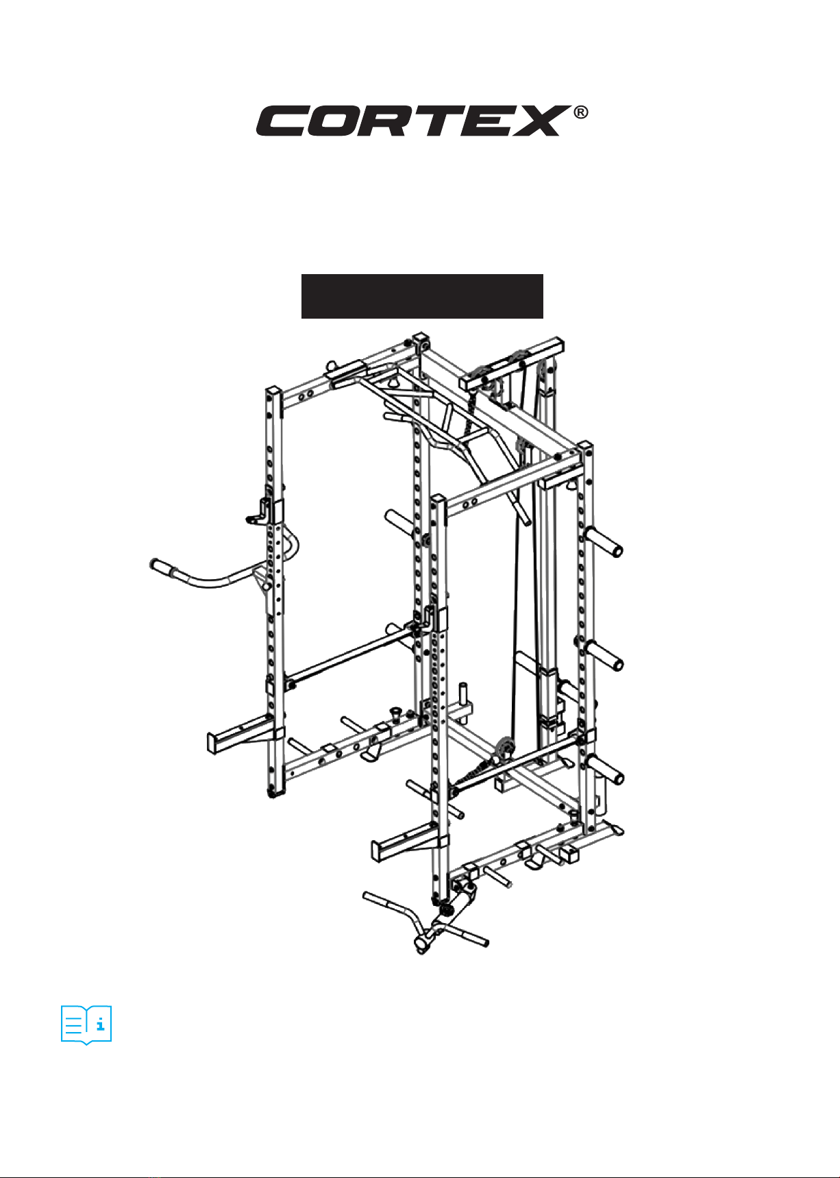
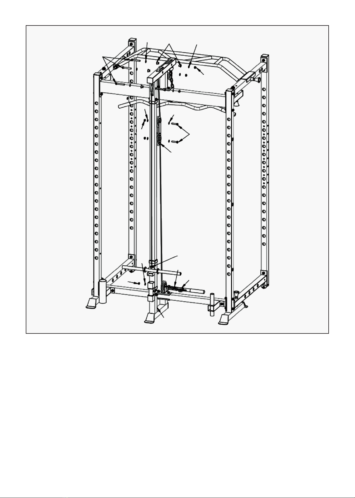
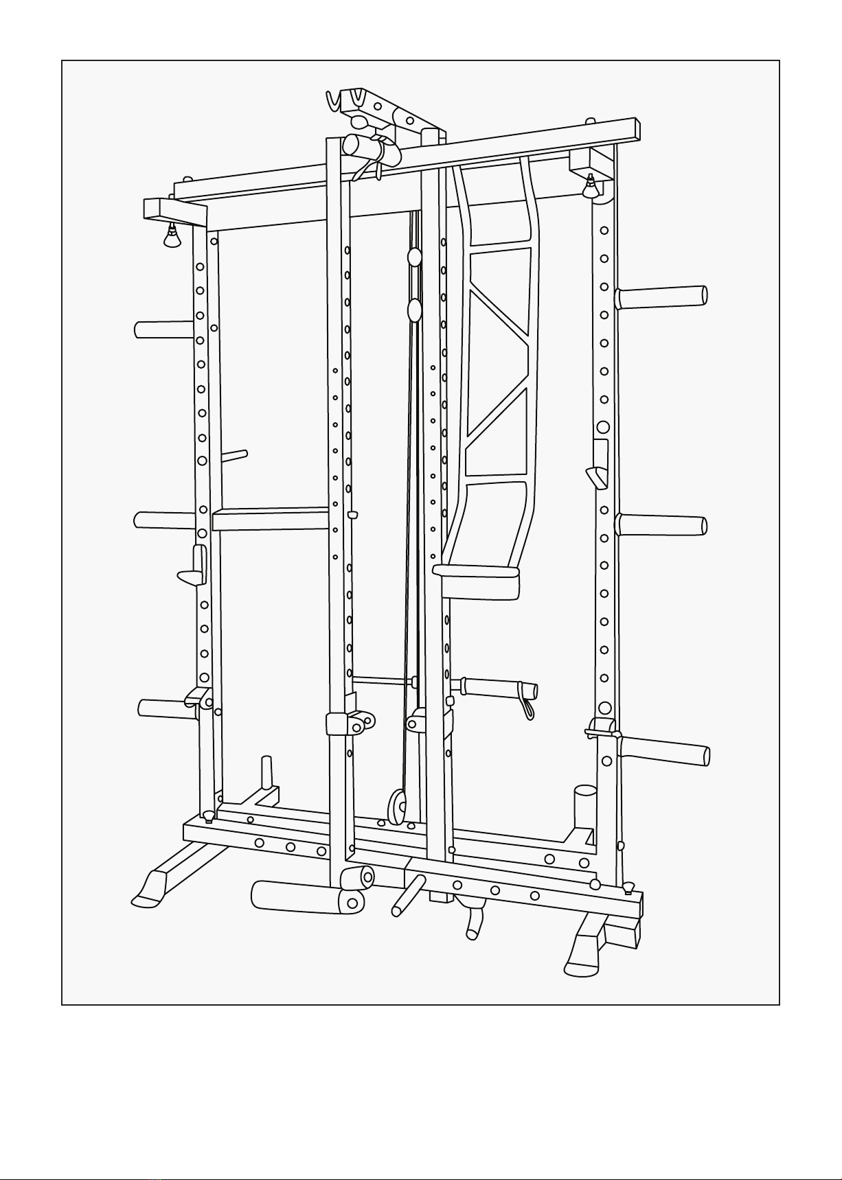
PR-4 Space Saver Folding
Squat Power Rack
USER MANUAL
Product may vary slightly from the item pictured due to model upgrades.
Read all instructions carefully before using this product.
Retain this owner’s manual for future reference.
NOTE:
This manual may be subject to updates or changes. Up to date manuals are available through our
website at www.lifespanfitness.com.au

2
TABLE OF
CONTENTS
I. Important Safety Instructions . . . . . . . . . . . . . . . . . . . . . . . . . . . . . . . . 03
II. Care Instructions . . . . . . . . . . . . . . . . . . . . . . . . . . . . . . . . . . . . . . . . . . . . . 04
III. Parts List . . . . . . . . . . . . . . . . . . . . . . . . . . . . . . . . . . . . . . . . . . . . . . . . . . . . . 05
IV. Assembly Instructions . . . . . . . . . . . . . . . . . . . . . . . . . . . . . . . . . . . . . . . . 08
V. Folding Instructions . . . . . . . . . . . . . . . . . . . . . . . . . . . . . . . . . . . . . . . . . . . 16
VI. Exercise Guide . . . . . . . . . . . . . . . . . . . . . . . . . . . . . . . . . . . . . . . . . . . . . . . . 18
VII. Warranty . . . . . . . . . . . . . . . . . . . . . . . . . . . . . . . . . . . . . . . . . . . . . . . . . . . . . 20
| TABLE OF CONTENTS

3IMPORTANT SAFETY INSTRUCTIONS |
I. IMPORTANT SAFETY
INSTRUCTIONS
WARNING: Read all instructions before using this machine.
To ensure your safety, read the following precautions before using this product
1. Please read, study and understand the instructions and all warning labels before use.
(It is recommended to be familiar with the normal operation and use methods of the device before
using this product. Information is available on this manual and at local retailers).
2. Please keep this manual and ensure that all the warning labels are clear and complete.
3. This product is recommended to install by more than two people.
4. Please consult your doctor’s advice before starting the exercise.
5. Please ensure safety when the children are present.
6. Be careful when using it with children present.
7. Please check any signs of wear of the wire rope regularly. If there is wear, it may cause some danger
to you.
8. Please keep your hands, limbs and clothes stretch to use the device.
9. Please note any signs of machinery that may occur, including part wear, loose hardware, and welding
cracks. Stop using the device with the above signs immediately and contact the after-sales service
department of our company.
10. You can complete the assembly with a wrench, or an inner hexagon wrench.
11. The product is subject to change without notice and the final interpretation belongs to the Division.

4| CARE INSTRUCTIONS
II. CARE INSTRUCTIONS
•Lubricate moving joints with silicon spray after periods of usage.
•Be careful not to damage plastic or metal parts of the machine with heavy or sharp objects.
•The machine can be kept clean by wiping it down using dry cloth.
•Check and adjust the tension of wire rope on a regular basis.
•Regularly check all moving parts and make sure there are signs of wear and damage, if any the use of
the device must be stopped immediately and contact our after-sales department.
•During inspection, it is necessary to make sure that all bolts and nuts are completely fixed. If any bolt
or nut connection is loosened, please re-tighten.
•Check weld for cracks.
•Failure to perform daily maintenance may result in personal injury or equipment damage.

5PARTS LIST |
III. PARTS LIST
No. Name Qty.
1Left Rear Column 1
2Right Rear Column 1
3Front Columns 2
4Rear Top Beam 1
5Rear Lower Beam 1
6Upper Left Connecting Frame 1
7Upper Right Connecting Frame 1
8Lower Left Connecting Frame 1
9Lower Right Connecting Frame 1
10 Chin Up Frame 1
11 Stainless Steel Tube 1
12 Top Pulley Guide 1
13 External Slide Rack 1
14 Post-support Floor Frame 1
15 Dip Bar 1
16 Barbell Holder 50mm 1
17 Barbell Holder 25mm 1
18 J Hooks 2
19 Safety Bar 2
20 Landmine Handle 1
21 Curl Lat Pull Down Bar 1
22 Straight Row Bar 1
23 Landmine Post 1
24 Horizontal Bar Bracket 4
25 Band Holders 4
26 Plate Holder Rods 4
27 Sleeve 8
No. Name Qty.
28 Horizontal Bar 2
29 Filament Axis 1
30 Short Wire Shaft 2
31 Pulley Bracket 1
32 Adjustment Sheet 2
33 Landmine Bracket 1
34 Landmine Steering 1
35 Pulley 6
36 M10 Knob 3
37 Switch Pin 5
38 Pulley Spacer Sleeve 6
39 Type C Buckle 4
40 7 Section Chain 2
41 Φ50 Spring collars 8
42 Short Cable 2940mm
Long Cable 3050mm 2
43 External Hexagon Bolt M12*80 4
44 External Hexagon M10*120 2
45 External Hexagon M10*70 28
46 External Hexagon M10*45 3
47 External Hexagon M10*20 12
48 Φ10 Flat Gasket 54
49 Φ10 Increase the Flat Gasket 8
50 Φ12 Flat Gasket 8
51 M12 Lock Nut 4
52 M10 Lock Nut 37
53 Ball Stud 1

6| PARTS LIST
1 2 3 4 5
6 7 8 9 10
11 12 13 14 15
16 17 18 19 20
21 22 23 24 25
26 27 28 29 30

7PARTS LIST |
31 32 33 34 35
36 37 38 39 40
41 42 43 44 45
46 47 48 49 50
51 52 53

8| ASSEMBLY INSTRUCTIONS
IV. ASSEMBLY INSTRUCTIONS
1. Place the (4#) Rear top beam and (5#) rear lower beam on both sides of (1 #) Left rear column and
(2#) Right rear column according to the figure. Then secure with (45#) bolts and (48#) spacer,
(52#) nut.
2. Place (16#) Barbell holder 50mm and (17#) Barbell holder 25mm on opposite holes on (5#) and secure
with (45#) bolts, flat gasket (48#) and nuts (52#).
STEP 1
IMPORTANT:
1. The gasket shall be placed at both ends of the bolt (against bolt head and nut), unless otherwise
indicated.
2. Preliminary assembly is to tighten all bolts and nuts by hand and tighten with a wrench for
complete assembly.
3. Some parts are pre-assembled in the factory.
4. You may require 2 people for this assembly.
4
52
48
48
45
2
45
45 48
48
52
52
48
48
52
5
48
45
17
1
16

9
1. Connect the (8#) Lower left connecting frame and (1#) with (49#) Φ10 Increase the flat gasket and
(52#) M10 lock nut according to the diagram. Then insert the (37#) Switch pin into (8#) and (1#).
2. Connect the Upper left connection frame (6#) and (1#) according to the figure. Insert the hole into the
(30#) short wire shaft and secure with (47#) External hexagon M10*20, (49#) Increase the flat gasket,
and then lock in (37#) Switch pin.
3. Connect (3#) front column and (6#) and (8#) according to the diagram, and secure with bolts (45#)
External hexagon M10*70, (48#) Φ10 flat gasket and (52#) M10 lock nut.
4. Repeat the same on the other side.
STEP 2
ASSEMBLY INSTRUCTIONS |
7
47
49
49 30
652
48
3
45
37
47
1
2
93
45
48
52
8
37
52
49

10 | ASSEMBLY INSTRUCTIONS
1. Place the (10#) Chin up frame on both sides of (6#) and (7#) according to the diagram, then insert
(29#) long shaft and secure with (49#) Φ10 Increase the flat gasket and (47#) External hexagon
M10*20.
2. Insert (37#) into (7#) and (10#).
STEP 3
47 49
10
37
7
29
49
47
6

11
1. Place (14#) Post-support floor frame to the bottom of (5#) and (31#) Pulley bracket to the top of (5#)
and (14#). Secure the parts with (45#) External hexagon M10*70, (48#) Φ10 flat gasket and (52#)
M10 lock nut.
2. Insert (11#) Stainless steel tube into (13#) External slide rack and then secure it into (14#) with (45#)
External hexagon M10*70, (48#) Φ10 flat gasket, and (52#) M10 lock nut.
3. Connect (12#) Top pulley guide to (4#) Rear top beam and (11#) Stainless steel tube and secure with:
•(44#) External hexagon M10*120
•(45#) External hexagon M10*70
•(48#) Φ10 flat gasket
•(52#) M10 lock nut
STEP 4
ASSEMBLY INSTRUCTIONS |
12
45
48
44
4
48
52
11
13
48
52 45
31
48
45
5
14

12 | ASSEMBLY INSTRUCTIONS
Cable guide.
Refer to step 6 for securing the pulleys.
STEP 5
NOTE:
Be sure to install the wire rope before installing the pulley.
3050mm
2940mm

13
1. Secure the three top pulley sections with (38#) Pulley spacer sleeve on each side and tighten with
(45#) External hexagon M10*70, (48#) Φ10 flat gasket and (52#) M10 lock nut.
2. Secure the two middle pulley to (32#) Adjustment sheet with (46#) External hexagon M10*45, (48#
Φ10 flat gasket and (52 #) M10 lock nut.
3. Secure the long cable (3050mm) to part (13#) External slide rack using (47#) External hexagon
M10*20.
4. Secure the bottom pulley using (46#) External hexagon M10*45, (48#) Φ10 flat gasket and (52#)
M10 lock nut.
5. You can attach the parts (40#) chain, (39#) C Buckle to accessories (21#) Curl lat pulldown bar and
(22#) Straight bar then attach it to the installed cables as pictured.
STEP 6
ASSEMBLY INSTRUCTIONS |
48 48
38
45
52
48
48
52 46
32
48
48
47
46
52
47

14 | ASSEMBLY INSTRUCTIONS
1. Connect (26#) Plate holder rods to (1#) Left rear column as shown and secure with (47#) External
hexagon M10*20 and (48#) Φ10 flat gasket for the Top and Bottom holders. For the middle holder
secure it with (36#) M10 knob. Insert (27#) Sleeve onto (26#) and repeat for the other side.
2. Place (24#) Horizontal bar bracket into the holes on columns (1#) and (3#). Next secure (28#)
Horizontal bar onto (24#) with (43#) External hexagon boltM12*80, (50#) Φ12 flat gasket and (51#)
M12 lock nut. Repeat for the other side.
3. Attach (33#) Landmine bracket onto (9#) Lower right connecting frame with (45#) External hexagon
M10*70, (48#) Φ10 flat gasket and (52#) M10 lock nut. Install (36#) M10 knob onto (23#) Landmine
post. Turn (34#) Landmine steering to connect to (23#) and (33#), and secure with pre-loaded bolt
and nuts.
STEP 7
27 26
31
48
47
43
28
50
50
24
51
51
47
48
50
24
36
2
934
33
45
36
23

15ASSEMBLY INSTRUCTIONS |
1. Fit the (15#) Dip bar onto the post (3#) and lock with (53#) Ball stud to use.
2. Slot the (18#) J hooks and (19#) Safety bar to preferred heights on post.
3. Slot in the (25#) on the bottom beams to use.
4. Part (20#) landmine handle can be secured to a barbell (25mm or 50mm) when using the landmine
post.
Once your equipment installation is complete, lock all the bolts and nuts with a wrench.
STEP 8
18
15
53
25
19
20

16
V. FOLDING INSTRUCTIONS
1. First, loosen and pull the Switch pin to unlock on the Pull up frame and move the frame to the
other side.
2. Loosen and unlock by pulling the Switch pins up on the frame (top and bottom). Once this is unlocked
you can fold the left side frame inwards.
3. Move the pull up frame so it is facing down (to the ground) and repeat the same step 2 for the right
side of the frame. NOTE: When folding in the right side of the frame, you will need to hold the
landmine post so it does not scrap the floor.
4. Un-folding steps will be in reverse. Ensure to fully lock in the pins when un-folding.
| FOLDING INSTRUCTIONS

17
Folded Diagram
FOLDING INSTRUCTIONS |

18
VI. EXERCISE GUIDE
PLEASE NOTE:
Before beginning any exercise program, consult your physician. This is important for individuals over
the age of 45 or with pre-existing health problems.
The pulse sensors are not medical devices. Various factors, including the user’s movement, may
affect the accuracy of heart rate readings. The pulse sensors are intended only as an exercise aid in
determining heart rate trends in general.
Exercising is great way to control your weight, improve your fitness and reduce the effect of aging and
stress. The key to a healthy lifestyle is to make exercise a regular and enjoyable part of your everyday
life.
The condition of your heart and lungs and how efficient they are in delivering oxygen via your blood to
your muscles is an important factor to your fitness. Your muscles use this oxygen to provide enough
energy for daily activity. This is called aerobic activity. When you are fit, your heart will not have to work
so hard. It will pump a lot fewer times per minute, reducing the strain on your heart.
So as you can see, the fitter you are, the healthier and greater you will feel.
WARM UP
Start each workout with 5 to 10 minutes of stretching and some light exercises. A proper warm-up
increases your body temperature, heart rate and circulation in preparation for exercise. Ease into your
exercise.
After warming up, increase the intensity to your desired exercise program. Be sure to maintain your
intensity for maximum performance. Breathe regularly and deeply as you exercise.
| EXERCISE GUIDE

19
COOL DOWN
Finish each workout with a light jog or walk for at least 1 minute. Then complete 5 to 10 minutes of
stretching to cool down. This will increase the flexibility of your muscles and will help prevent post-
exercise problems.
WORKOUT GUIDELINES
This is how your pulse should behave during general fitness exercise. Remember to warm up and
cool down for a few minutes.
TARGET ZONE
MAXIMUM
85%
70%
COOL DOWN
AGE
HEART RATE
200
180
160
140
120
100
80
20 25 30 35 40 45 50 55 60 65 70 75
EXERCISE GUIDE |

20
VII. WARRANTY
AUSTRALIAN CONSUMER LAW
Many of our products come with a guarantee or warranty from the manufacturer. In addition, they come
with guarantees that cannot be excluded under the Australian Consumer Law. You are entitled to a
replacement or refund for a major failure and compensation for any other reasonably foreseeable loss
or damage.
You are entitled to have the goods repaired or replaced if the goods fail to be of acceptable quality and
the failure does not amount to a major failure. Full details of your consumer rights may be found at
www.consumerlaw.gov.au.
Please visit our website to view our full warranty terms and conditions:
http://www.lifespanfitness.com.au/warranty-repairs
WARRANTY AND SUPPORT
Any claim against this warranty must be made through your original place of purchase.
Proof of purchase is required before a warranty claim may be processed.
If you have purchased this product from the Official Lifespan Fitness website, please visit
https://lifespanfitness.com.au/warranty-form
For support outside of warranty, if you wish to purchase replacement parts or request a repair or
service, please visit https://lifespanfitness.com.au/warranty-form and fill in our Repair/Service
Request Form or Parts Purchase Form.
Scan this QR code with your device to go to lifespanfitness.com.au/warranty-form
| WARRANTY
Table of contents
Other Cortex Fitness Equipment manuals

Cortex
Cortex Omega RWP-10 User manual

Cortex
Cortex PR-3 User manual

Cortex
Cortex Omega SRP-10 User manual

Cortex
Cortex LGE-10 User manual

Cortex
Cortex BN-11 User manual

Cortex
Cortex GS7 User manual

Cortex
Cortex BH-8 User manual

Cortex
Cortex LP-1 User manual

Cortex
Cortex GS6 User manual

Cortex
Cortex Omega LGP-10 User manual

Cortex
Cortex Omega Series User manual

Cortex
Cortex SS2 User manual

Cortex
Cortex SM-10 User manual

Cortex
Cortex SM25 User manual

Cortex
Cortex FID11 Alpha Series User manual

Cortex
Cortex SM26 Multi Gym User manual

Cortex
Cortex WTS1 User manual

Cortex
Cortex MF420 User manual

Cortex
Cortex BN-7 User manual

Cortex
Cortex Omega SHM-10 User manual