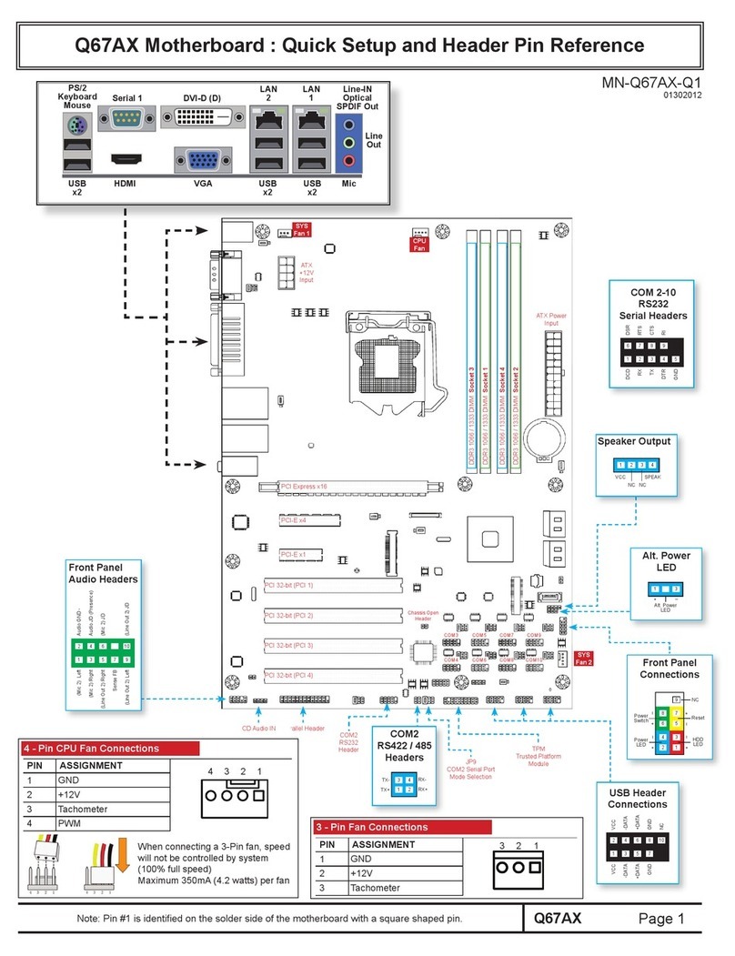
Corvalent Gator 550-G User manual

Gator 550-
G
Motherboard
Installation Guide


Introduction
Table of Contents
Notice........................................................ III
Introduction...........................................IV
Chapter 1 Pre-Configuration...... 1
Step 1 Setting the Jumpers 3
Jumper Locations ............................................................. 4
CMOS Reset....................................................................... 5
ATA-Disk Connector Voltage Selection.......................... 5
LCD Power Voltage Selection.......................................... 5
Step 2 DRAM and Cables Installation 6
Gator 550-G Memory Configuration................................ 6
Installing Cables ............................................................... 7
Power and Control Panel Cables .................................... 7
Installing Peripheral Cables............................................. 7
Index of Connectors ......................................................... 9
Chapter 2 HIFLEX BIOS Setup .
........................................... 11
Standard Setup ............................................................... 12
Advanced CMOS Setup .................................................. 13
Advanced Chipset Setup................................................ 17
Power Management Setup ............................................. 18
PCI/Plug and Play Setup ................................................ 20
Peripheral Setup ............................................................. 23
Auto Detect Hard Disk .................................................... 25
Change User Password.................................................. 26
Change Supervisor Password ....................................... 26
Auto Configuration with Optimal Settings ................... 26
Auto Configuration with Fail-Safe Settings.................. 27
Save Settings and Exit ................................................... 27
Exit without Saving......................................................... 27
Post Codes ...................................................................... 27
I

Gator 550-G – Installation Guide
Chapter 3 Upgrading.................... 37
Upgrading the System Memory..................................... 37
Appendix A Technical
Specifications ..................................... 39
Chipset ............................................................................. 39
Bios .................................................................................. 40
Embedded I/O.................................................................. 40
Miscellaneous ................................................................. 42
Memory Map .................................................................... 43
DMA Channels................................................................. 43
I/O Map ............................................................................. 44
PCI Configuration Space Map........................................ 45
Interrupts ......................................................................... 46
PCI Interrupt Routing Map ............................................. 46
SMBUS ............................................................................. 47
Connectors Pin-out......................................................... 47
Appendix B Flash BIOS
programming ........... 59
Appendix C On-board Video .... 61
Appendix D On-Board Industrial
Devices........................ 63
On-board Ethernet .......................................................... 63
Serial Ports ...................................................................... 65
II

Introduction
Notice
The company reserves the right to revise this publication or to change
its contents without notice. Information contained herein is for
reference only and does not constitute a commitment on the part of the
manufacturer or any subsequent vendor. They are in no way
responsible for any loss or damage resulting from the use (or misuse) of
this publication.
This publication and any accompanying software may not, in whole or
in part, be copied, photocopied, translated or reduced to any machine
readable form without prior consent from the vendor, manufacturer or
creators of this publication, except for copies kept by the user for
backup purposes.
Brand and product names mentioned in this publication may or may not
be copyrights and/or registered trademarks of their respective
companies. They are mentioned for identification purposes only and are
not intended as an endorsement of that product or its manufacturer.
First Edition.
January, 2005
III

Gator 550-G – Installation Guide
Introduction
Thank you for your purchase of the Gator 550-G industrial embedded
motherboard. The Gator 550-G design was based on the SiS550 SoC
(System on Chip) providing the ideal platform to industrial low power
applications.
With proper installation and maintenance, your Gator 550-G will
provide years of high performance and trouble free operation.
This manual provides a detailed explanation into the installation and
use of the Gator 550-G industrial embedded motherboard. This manual
is written for the novice PC user/installer. However, as with any major
computer component installation, previous experience is helpful and
should you not have prior experience, it would be prudent to have
someone assist you in the installation. This manual is broken down into
3 chapters and 4 appendixes.
Chapter 1 - System Board Pre-Configuration
This chapter provides all the necessary information for
installing the Gator 550-G. Topics discussed include:
installing the DRAM, jumper settings and connecting all the
cables from the system board to the chassis and peripherals.
Chapter 2 - BIOS Configuration
This chapter shows the final step in getting your system
firmware setup.
Chapter 3 - Upgrading
The Gator 550-G provides expansion options for the memory.
All aspects of the upgrade possibilities are covered.
Appendix A - Technical Specifications
A complete listing of all the major technical specifications of
the Gator 550-G is provided.
IV

Introduction
Appendix B - Flash BIOS Programming (optional)
Provides all the information necessary to program your
optional AMIBIOS Flash BIOS.
Appendix C – On-board Video Controller
On-board CRT, LCD and LVDS (optional) video controller.
Appendix D - On-Board Industrial Devices
One on-board 10/100 Ethernet and four serial ports (one
optional RS422/485).
Static Electricity Warning!
The Gator 550-G has been designed as rugged as possible but can still
be damaged if jarred sharply or struck. Handle the motherboard with
care.
The Gator 550-G also contains delicate electronic circuits that can be
damaged or weakened by static electricity. Before removing the Gator
550-G from its protective packaging, it is strongly recommended that
you use a grounding wrist strap. The grounding strap will safely
discharge any static electricity build up in your body and will avoid
damaging the motherboard. Do not walk across a carpet or linoleum
floor with the bare board in hand.
Warranty
This product is warranted against material and manufacturing defects
for two years from the date of delivery. Buyer agrees that if this
product proves defective the manufacturer is only obligated to repair,
replace or refund the purchase price of this product at manufacturer's
discretion. The warranty is void if the product has been subjected to
alteration, misuse or abuse; if any repairs have been attempted by
anyone other than the manufacturer; or if failure is caused by accident,
acts of God, or other causes beyond the manufacturer's control.
V

Gator 550-G – Installation Guide
Gator 550-G - An Overview
The Gator 550-G represents the ultimate in industrial embedded
motherboard technology. No other system board available today
provides such impressive list of features:
SiS550 Overview
• The single chipset, SiS550 family, provides a high
performance/low cost SoC (System on Chip) solution by integrating
an x86 compatible processor (200MHz), high performance North
Bridge, advanced hardware GUI engine and Super-South bridge.
Memory
• One µDIMM socket up to 256MB SDRAM, PC100/133.
On-Board I/O
• 1 Floppy up to 2.88 MB.
• Single channel PCI 32-bit EIDE controller - UDMA
33/66/100 supported.
• Four high speed RS-232 serial ports 16 Bytes FIFO (16550)
(COM3 optional RS422/485) (COM2 optional RS-232 IrDA).
• One bidirectional parallel port. SPP mode compatible.
• One mouse and one keyboard interface.
• Two Universal Serial Bus interfaces.
• One PC104+ interface.
• One Ethernet interface.
• Power Button – advanced management support.
• Audio AC97 compliant. Microphone In, Stereo Line In, CD
In, headphone Out.
ROM BIOS
• AMI BIOS™ BIOS HIFLEX with optional FLASH ROM
VI

Introduction
On-Board CRT & LVDS video controller
• Standard CRT video controller .
• Standard LCD interface.
• Dedicated Local Flat Panel (LFP) LVDS interface (optional).
On-Board Ethernet
• On-board 10/100 Ethernet.
Conventions Used in this Manual
Notes - Such as a brief discussion of memory types.
Important Information - such as static warnings, o
r
very important instructions.
8
When instructed to enter keyboard keystrokes, the
text will be noted by this graphic.
VII

Chapter 1: Pre-Configuration
Chapter 1 Pre-Configuration
This chapter provides all the necessary information for installing the
Gator 550-G. Topics discussed include: installing the DRAM and
jumper settings.
Handling Precautions
The Gator 550-G has been designed to be as rugged as possible but it
can be damaged if dropped, jarred sharply or struck. Damage may also
occur by using excessive force in performing certain installation
procedures such as forcing the system board into the chassis or placing
too much torque on a mounting screw.
Take special care when installing or removing the system memory
DIMM. Never force a DIMM into a socket. Screwdrivers slipping off a
screw and scraping the board can break a trace or component leads,
rendering the board unusable. Always handle the Gator 550-G with
care.
Special Warranty Note:
Products returned for warranty repair will be
inspected for damage caused by imprope
r
installation and misuse as described in the
p
revious section and the static warning below.
Should the board show signs of abuse, the
warranty will become void and the customer wil
l
be billed for all repairs and shipping an
d
handling costs.
Static Warning
The Gator 550-G contains delicate electronic semiconductors that are
highly sensitive to static electricity. These components, if subjected to a
static electricity discharge, can be weakened thereby reducing the
serviceable life of the system board. BEFORE THE BOARD IS
REMOVED FROM ITS PROTECTIVE ANTISTATIC PACKAGING,
1

Gator 550-G – Installation Guide
TAKE PROPER PRECAUTIONS! Work on a conductive surface that
is connected to the ground. Before touching any electronic device,
ground yourself by touching an unpainted metal object or, and highly
recommended, use a grounding strap.
2

Chapter 1: Pre-Configuration
Step 1 Setting the Jumpers
Your Gator 550-G is equipped with a large number of peripherals and
has the ability to run at a variety of speeds without the need to change
any crystals or oscillators (Speeds can be set in the BIOS, the
maximum core speed is determined by the SoC installed). As such,
there are a large number of configuration jumpers on the board. Taken
step by step, setting these jumpers is easy. We suggest you review each
section and follow the instructions.
Jumper Types
Jumpers are small copper pins attached to the system board. Covering
two pins with a shunt closes the connection between them. The Gator
550-G examines these jumpers to determine specific configuration
information. There are three different categories of jumpers on the
Gator 550-G.
A. Two pin jumpers are used for binary selections such as enable,
disable. Instructions for this type of jumper are open, for no shunt over
the pins or closed, when the shunt covers the pins.
B. Three or four pin jumpers are used for multiple selections.
Instructions for these jumpers will indicate which two pins to cover.
For example: for JPx2-3 the shunt will be covering pins 2 and 3
leaving pins 1 and 4 exposed.
C. Grouped jumpers are used when a certain function has multiple
selections. There are two grouped jumpers on the board and careful
attention should be given when setting these jumpers. Instructions for
grouped jumpers are similar to those above.
How to identify pin number 1 on Figure 1-1: Looking to the solder side
(The board side without components) of the PCB (Printed Circuit
Board), pin number 1 will have a squared pad J. Other pins will have
a circular pad Q. They are numbered sequentially.
Double row jumpers are numbered alternately, i.e. pin number 2 is in
the other row, but in the same column of pin number 1. Pin number 3 is
in the same row of pin 1, but in the next column and so forth.
3

Gator 550-G – Installation Guide
Jumper Locations
Use the diagram below and the tables on the following pages to locate
and set the on-board configuration jumpers.
Figure 1-1 Jumper Locations
4

Chapter 1: Pre-Configuration
CMOS Reset
This option is provided as a convenience for those who need to reset
the CMOS registers. It should always be set to "Normal" for standard
operation. If the CMOS needs to be reset, turn off the system, move
JP33 to 2-3, turn the system on, move jumper to 1-2 and press reset.
Table 1-1 CMOS Reset
Reset CMOS Normal Clear CMOS
JP33 1-2* 2-3
* Manufacturer's Settings.
ATA-Disk Connector Voltage Selection
The ATA-Disk Connector J22 can provide either 5Vcc or 3.3Vcc. The
jumper JP1 selects the voltage.
Table 1-2 ATA-Disk Connector Voltage Select
ATA-Disk
Voltage 5Vcc 3.3Vcc
JP1 1-2* 2-3
*Manufacturer's Settings.
LCD Power Voltage Selection
The LCD Connector J14 can provide either 5Vcc or 3.3Vcc to the LCD
panel. The jumper J15 selects the voltage.
Table 1-3 LCD VDD Power Voltage Select
LCD Voltage 3.3Vcc 5Vcc
J15 1-2* 2-3
*Manufacturer's Settings.
5

Gator 550-G – Installation Guide
Step 2 DRAM and Cables Installation
Depending upon how your Gator 550-G is configured you may need to
install the µDIMM.
Gator 550-G Memory Configuration
The Gator 550-G offers 1 µDIMM memory socket (Location J12 -
Back side or solder side– Figure 1-2). It can be configured with 3.3V
unbuffered SDRAM module. It is very important that the quality of the
DIMM is good. Unreliable operation of the system may result if poor
quality DIMMs are used. Always purchase your memory from a
reliable source. Please, refer to chapter 3 for memory details.
Figure 1-2 µDIMM Location (Solder Side)
6

Chapter 1: Pre-Configuration
Installing Cables
Power and Control Panel Cables
The Gator 550-G gets power from the power connector J34 (Figure 1-
3).
Installing Peripheral Cables
Connect the combined flat cables to their connectors and to the other
end. This concludes the hardware installation of your Gator 550-G
system. Now it is a good time to re-check all of the cable connections
to make sure they are correct.
7

Gator 550-G – Installation Guide
Figure 1-3 Location of Components and Connectors
8

Chapter 1: Pre-Configuration
Index of Connectors
Please refer to Appendix A for pin-out descriptions.
Table 1-4 Connectors descriptions
Connector Description
J11 Reset
J12 µDIMM Slot (Back side)
J14 LCD Panel
J20 LVDS Panel
J21 PC104+
J22 IDE 44pin
J25 Combined FDD/USB/COM4/IrDA
J26 Combined COM1/COM2/COM3/Audio
J27 Ethernet 10/100
J30 Combined VGA/Keyboard/Mouse/LPT
J31 Power Button
J34 Power +12Vcc
J35 RTC Battery
J36 LVDS Backlight
J37 LPC
U14 BIOS Socket
User's Notes:
9

Gator 550-G – Installation Guide
User's Notes:
10

Chapter 2: BIOS Configuration
Chapter 2 HIFLEX BIOS
Setup
Your Gator 550-G features AMI BIOS. The system configuration
parameters are set via the HIFLEX AMIBIOS setup. Since HIFLEX
BIOS Setup resides in the ROM BIOS, it is available each time the
computer is turned on.
Starting BIOS Setup
As POST executes, the following appears:
Hit <DEL> if you want to run SETUP
Using the Keyboard with BIOS Setup
The BIOS Setup has a built-in keyboard driver that uses simple
keystroke combinations:
Keystroke Function
<Tab> Move to the next window or field.
, , , Move to the next field to the right, left, above, or below.
<Enter> Select in the current field.
+ Increments a value.
- Decrements a value.
<Esc> Closes the current operation and return to previous level.
<PgUp> Returns to the previous page.
<PgDn> Advances to the next page.
<Home> Returns to the beginning of the text.
<End> Advances to the end of the text.
<Alt> <H> Access a help window.
<Alt> <Spacebar> Exit WINBIOS Setup.
Alphabetic keys A to Z are used in the Virtual Keyboard, and are not case-
sensitive.
Numeric keys 0 to 9 are used in the Virtual Keyboard and Numeric Keypad.
BIOS Setup Main Menu
The BIOS Setup main menu is organized into 13 windows. Each
window is discussed in this chapter.
Each window contains several options. Clicking on each option
activates a specific function. The BIOS Setup options and
11
Table of contents
Other Corvalent Motherboard manuals

Corvalent
Corvalent Gator Mini-ITX User manual

Corvalent
Corvalent C246AX User manual

Corvalent
Corvalent H61SB User manual

Corvalent
Corvalent ATX User manual

Corvalent
Corvalent Q35SBC User manual

Corvalent
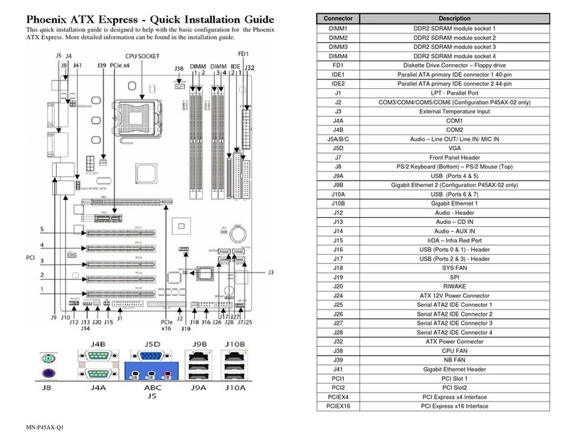
Corvalent Phoenix ATX Express User manual

Corvalent
Corvalent Q67AX Specification sheet

Corvalent
Corvalent C23AX User manual

Corvalent
Corvalent Q77AX User manual