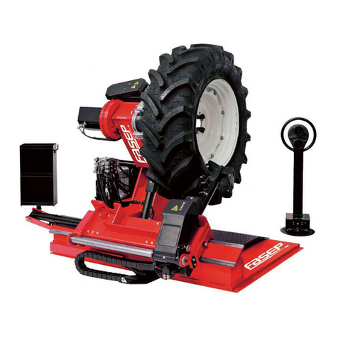
Fasep TOP AUTOMATIC 4.0 Operating instructions

OPERATING AND MAINTENANCE MANUAL
TYRE CHANGER
TOP AUTOMATIC 4.0
Serial no.: ___________
Manual version: UM TOP AUTOMATIC 4.0
FASEP 2000 Srl
Via Faentina, 96
50032 Ronta (Fi) ITALIA
Sede legale: Piazza d'Azeglio, 39 - 50121 Firenze
Tel: +39-055-8403126
Email: [email protected]
Skype: fasep2000
orario ufficio (8-12, 13-18, GMT+1). solo chiamate.
This manual is an integral part of the product and must always be available to the users of the product.

OPERATING AND MAINTENANCE MANUAL
RASE.TOP.4028
Code DOC. UM TOP AUTOMATIC 4.0
Rev. 6
Page 2 of 86
2
Blank page

OPERATING AND MAINTENANCE MANUAL
RASE.TOP.4028
Code DOC. UM TOP AUTOMATIC 4.0
Rev. 6
Page 3 of 86
3
TABLE OF CONTENTS
TABLE OF CONTENTS - FIGURES...........................................................................................................5
1 GENERAL INFORMATION................................................................................................................7
1.1 Layout of the manual...............................................................................................................7
1.1.1 Purpose and intended recipients ......................................................................................7
1.1.2 - Storing ................................................................................................................................7
1.1.3 Symbols used within the manual ......................................................................................8
1.2 - Manufacturer............................................................................................................................8
1.3 Service centres.........................................................................................................................8
1.4 - Certification and CE Marking....................................................................................................9
1.5 WDK CERTIFICATION..............................................................................................................10
1.6 - Warranty.................................................................................................................................11
2 DESCRIPTION OF THE MACHINE...................................................................................................12
2.1 - Main units...............................................................................................................................13
2.1.1 - Machine frame.................................................................................................................14
2.1.2 Control panel...................................................................................................................15
2.1.3 Rear cabinet and electric panel.......................................................................................16
2.1.4 Electric panel compartment............................................................................................17
2.1.5 - Self-centring unit..............................................................................................................18
2.1.6 - Upper tool unit.................................................................................................................18
2.1.7 - Lower tool unit.................................................................................................................19
2.1.8 - Tecnoservice unit .............................................................................................................19
2.1.9 Lifter.................................................................................................................................20
2.1.10 Pedals ............................................................................................................................21
2.2 CE plate ..................................................................................................................................22
2.3 - Specifications..........................................................................................................................23
3 SAFETY..........................................................................................................................................25
3.1 General warnings...................................................................................................................25
3.2 - Danger zones ..........................................................................................................................26
3.3 - Safety guards ..........................................................................................................................26
3.4 - Emergency button ..................................................................................................................27
3.5 - Residual risks ..........................................................................................................................28
3.6 Personal protective equipment.............................................................................................29
3.7 Safe work procedures............................................................................................................29
3.7.1 Safety rules for the operator...........................................................................................29
Safety rules for the mechanical maintenance engineer .................................................30
3.7.3 Safety rules for the electrical maintenance engineer.....................................................30
4 HANDLING AND INSTALLATION ...................................................................................................31
4.1 Preparations the customer is responsible for .......................................................................31
4.2 Handling.................................................................................................................................35
4.3 Positioning .............................................................................................................................36
4.4 Preliminary operations at the first startup............................................................................37
4.5 Long periods of inactivity.......................................................................................................37
5 OPERATING THE MACHINE ..........................................................................................................40

OPERATING AND MAINTENANCE MANUAL
RASE.TOP.4028
Code DOC. UM TOP AUTOMATIC 4.0
Rev. 6
Page 4 of 86
4
5.1 INTENDED USE .......................................................................................................................40
5.2 Inappropriate use ..................................................................................................................40

5.3 Starting the machine..............................................................................................................41
5.4 Operating modes ...................................................................................................................44
5.4.1 Automatic mode..............................................................................................................44
5.4.2 Manual mode ..................................................................................................................55
5.5 Diagnostics.............................................................................................................................65
5.5.1 Finished work cycle reports.............................................................................................65
5.5.2 Rim geometry diagnostics ...............................................................................................69
.................................................................69
6 MAINTENANCE.............................................................................................................................73
6.1 Safety precautions .................................................................................................................74
6.2 Disconnecting and putting out of service..............................................................................74
6.3 Ordinary maintenance...........................................................................................................75
6.4 Extraordinary maintenance ...................................................................................................76
7 TROUBLESHOOTING.....................................................................................................................78
8 DISMANTLING AND DISASSEMBLY...............................................................................................80
9 DISPOSAL AND DEMOLITION .......................................................................................................82
10 ATTACHMENTS...........................................................................................................................84
10.1 Pneumatic diagram / layout ................................................................................................85
10.2 Hydraulic diagram / layout ..................................................................................................86
10.3 Spare parts list .....................................................................................................................86

OPERATING AND MAINTENANCE MANUAL
RASE.TOP.4028
Code DOC. UM TOP AUTOMATIC 4.0
Rev. 6
Page 5 of 86
5
TABLE OF CONTENTS - FIGURES
Figure 1 Facsimile of EC Declaration of Conformity .......................................................................10
Figure 2 Overall view of the machine .............................................................................................13
Figure 3 Locking cones ....................................................................................................................14
Figure 4 Machine frame..................................................................................................................14
Figure 5 Control panel.....................................................................................................................15
Figure 6 Rear cabinet ......................................................................................................................16
Figure 7 Electric panel compartment..............................................................................................17
Figure 8 Self-centring unit...............................................................................................................18
Figure 9 Upper tool unit..................................................................................................................18
Figure 10 Lower tool .......................................................................................................................19
Figure 11 Tecnoservice unit ............................................................................................................19
Figure 12 Lifter ................................................................................................................................20
Figure 13 Pedals...............................................................................................................................21
Figure 14 CE plate ...........................................................................................................................22
Figure 15 CE plate location .............................................................................................................23
Figure 16 Emergency button (a) and main power switch (b) .........................................................27
Figure 17 Position of pictograms showing residual risks................................................................28
Figure 18 .....................................................................................................32
Figure 19 Connection points to power sources ..............................................................................33
Figure 20 Machine hoisting.............................................................................................................35
Figure 21 Adjustable leg..................................................................................................................36
Figure 22 Touch-screen for work cycle monitoring ........................................................................43
Figure 23 Key..........................................................................................................65
Figure 24 ..................................................................................................65
Figure 25 .............................................................................................................66
Figure 26 .............................................................................................66
Figure 27 Key.........................................................................................67
Figure 28 ......................................................................................................67
Figure 29 .....................................................................................................68
Figure 30 ...............................................................................................68
Figure 31 .......................................................................................................69
Figure 32 Ethernet port...................................................................................................................69
Figure 33 Machine connection to company network.....................................................................70
Figure 34 Machine-company network connection interface .........................................................70
Figure 35 Remote machine operation control window..................................................................71
Figure 36 Remote machine maintenance window.........................................................................71
Figura 37 ....................................................................................73
Figura 38 window.............................................................................73
Figure 39 Self-centring unit pin.......................................................................................................76

OPERATING AND MAINTENANCE MANUAL
RASE.TOP.4028
Code DOC. UM TOP AUTOMATIC 4.0
Rev. 6
Page 6 of 86
6
Blank page

OPERATING AND MAINTENANCE MANUAL
RASE.TOP.4028
Code DOC. UM TOP AUTOMATIC 4.0
Rev. 6
Page 7 of 86
7
1 GENERAL INFORMATION
1.1 LAYOUT OF THE MANUAL
This manual is an integral part of the official documentation of the tyre changer machine,
ade available to
users and servicemen.
The user and serviceman must carefully read the information in this manual in order to properly
install and operate the machine.
FASEP ny
damage caused during the operation of the machine due to the incorrect application of the safety
concepts in this manual.
1.1.1 Purpose and intended recipients
The purpose of this manual is to provide the information required to operate and service the
machine.
Any work on the machine must be performed by a specially trained operator. Servicemen and
operating personnel must read and understand the instructions in this manual.
The employer is responsible for training operators on risks due to injury and the regulations to
prevent them which are in force in the country where the machine has been installed.
In the event of any doubts concerning the proper interpretation of these instructions, please
contact the Manufacturer for any explanations necessary.
This manual is intended for the operator and the technicians appointed with servicing the
machine.
1.1.2 - Storing
The User Manual must be stored close to the machine in a specific container and protected from
liquids and anything else which may make it illegible.

OPERATING AND MAINTENANCE MANUAL
RASE.TOP.4028
Code DOC. UM TOP AUTOMATIC 4.0
Rev. 6
Page 8 of 86
8
1.1.3 Symbols used within the manual
SYMBOL
MEANING
Warning
This symbol is used in the safety messages in the following two
cases:
to highlight important information for the servicemen and
operating personnel;
to point out safety measures to be implemented to avoid
damaging the machine.
This symbol is used in the safety messages (rules) in the manual
when potentially hazardous situations exist or it is probable for
persons using the machine to be injured.
1.2 - MANUFACTURER
FASEP 2000 Srl
Via Faentina, 96
50032 Ronta (Fi) ITALIA
Tel: +39-055-8403126
Email: [email protected]
Skype: fasep2000
1.3 SERVICE CENTRES
The Manufacturer assembles the machine. Specialized FASEP personnel or an authorized FASEP
Service Centre must be contacted for any servicing required on the machine.

OPERATING AND MAINTENANCE MANUAL
RASE.TOP.4028
Code DOC. UM TOP AUTOMATIC 4.0
Rev. 6
Page 9 of 86
9
1.4 - CERTIFICATION AND CE MARKING
The machine was manufactured in compliance with Directive 2006/42/EC and with the pertinent
and applicable EU Community Directives at the time it was put on the market (Fig. 1).
DECLARATION OF CONFORMITY
(Encl. II A, Part I, Selection A- Machinery Directive 2006/42/EC)
Declares under the sole resposability of its legal representative that the machine:
Name: Tyre Changer
Model RASE.TOP.4028
Year:
Serial No:
Absorbed power: 3.5 kW
Weight: 780Kg
Conforms with the safety requirements set forth by:
Machinaru Directive 2006/42/EC
Electromagnetic Compatibility Directive 2004/108/EC
Name and Surname.............................

OPERATING AND MAINTENANCE MANUAL
RASE.TOP.4028
Code DOC. UM TOP AUTOMATIC 4.0
Rev. 6
Page 10 of 86
10
Figure 1 Facsimile of EC Declaration of Conformity
1.5 WDK CERTIFICATION
RASE.TOP 4028 tyre changer complies with the requirements of the German Rubber
Wirtschaftsverband der deutschen Kautschukindustrie) WDK directive, 2016 edition
(Test report K170853 dated 29 June 2017), with reference to the properties tested.

OPERATING AND MAINTENANCE MANUAL
RASE.TOP.4028
Code DOC. UM TOP AUTOMATIC 4.0
Rev. 6
Page 11 of 86
11
1.6 - WARRANTY
The warranty covers the machine for 24 months starting from the date the Manufacturer ships the
machine to the customer.

OPERATING AND MAINTENANCE MANUAL
RASE.TOP.4028
Code DOC. UM TOP AUTOMATIC 4.0
Rev. 6
Page 12 of 86
12
2DESCRIPTION OF THE MACHINE
The tyre changer machine (the subject of this Operating and Maintenance Manual) allows a tyre to
be changed on different types of wheels, in an easy and safe manner for the operator.
Its innovative tilting system of the self-centring unit (where the wheel is positioned) facilitates
bead-breaking operations while decreasing the need for the operator to intervene on the tyre
using manual tools.
The “RASE.TOP 4028”machine is completed by a PLC control system and by a dedicated electric
panel.

OPERATING AND MAINTENANCE MANUAL
RASE.TOP.4028
Code DOC. UM TOP AUTOMATIC 4.0
Rev. 6
Page 13 of 86
13
2.1 - MAIN UNITS
The tyre changer consists of the following units (figure 2):
Figure 2 Overall view of the machine
7
5
3
1
4
8
2
6
1. Machine frame.
2. Control panel.
3. Rear cabinet.
4. Electric panel
compartment.
5. Self-centring unit.
6. Upper tool unit.
7. Lower tool.
8. Tecnoservice unit.
9. Lifter.
10. Pedals.
9
10

OPERATING AND MAINTENANCE MANUAL
RASE.TOP.4028
Code DOC. UM TOP AUTOMATIC 4.0
Rev. 6
Page 14 of 86
14
Depending on the tyre and related wheel rim, it is possible to select from three types of locking
cones (Fig. 3):
Figure 3 Locking cones
The average life (under normal operating conditions) of the tyre changer is estimated at 20 years.
Once this period is over, the machine may undergo a complete overhaul/check by contacting the
Department.
2.1.1 - Machine frame
The machine framework consists of an extremely compact tubular monobloc which is easy to
handle (Fig. 4).
Figure 4 Machine frame

OPERATING AND MAINTENANCE MANUAL
RASE.TOP.4028
Code DOC. UM TOP AUTOMATIC 4.0
Rev. 6
Page 15 of 86
15
2.1.2 Control panel
The operator controls the automatic pneumatic removal/fitting cycle using the touch screen unit
that is incorporated into the control panel, which includes the selectors to activate machine tool
movements in manual mode, the start and emergency buttons, and lifter selectors (Fig. 5):
Figure 5 Control panel
1) Touch-screen unit.
2) UPPER TOOL UNIT RAISE/LOWER lever
and LH/RH TRANSLATION LEVER FOR
THE SELF-CENTRING UNIT.
3) TECNOSERVICE UNIT RAISE/LOWER
lever.
4) Self-centring unit axis VERTICAL/TILTED
positioning lever.
5) LOWER TOOL RAISE/LOWER lever.
6) WHEEL LOCK/UNLOCK selector switch.
7) MANUAL/AUTOMATIC mode selector.
8) UPPER TOOL SELECTOR.
9) LIFTER vertical translation selector.
10) LIFTER rotation selector.
11) EMERGENCY button.
12) START button.
1
2
3
4
5
7
6
9
8
10
1
2 3 4
5 6 7
8 9 10
11 12

OPERATING AND MAINTENANCE MANUAL
RASE.TOP.4028
Code DOC. UM TOP AUTOMATIC 4.0
Rev. 6
Page 16 of 86
16
2.1.3 Rear cabinet and electric panel
The cabinet in the back of the machine (Fig. 6) holds the hydrauliccontrol unit (a), the upper tool
rotation unit (b) and the solenoid valve unit (c).
Figure 6 Rear cabinet
a
b
c

OPERATING AND MAINTENANCE MANUAL
RASE.TOP.4028
Code DOC. UM TOP AUTOMATIC 4.0
Rev. 6
Page 17 of 86
17
2.1.4 Electric panel compartment
The electric panel compartment (Fig. 7) holds the PLC (a), power supply unit (b), and inverters (c).
Figure 7 Electric panel compartment
a
b
c

OPERATING AND MAINTENANCE MANUAL
RASE.TOP.4028
Code DOC. UM TOP AUTOMATIC 4.0
Rev. 6
Page 18 of 86
18
2.1.5 - Self-centring unit
In addition to translating in the direction parallel to the machine base, the self-centring unit (Fig.
8) may be tilted during the tyre extraction step in order to reduce the stress applied to the bead of
the tyre during removal.
Figure 8 Self-centring unit
2.1.6 - Upper tool unit
The upper tool unit is used by the operator to break and extract the upper bead of the tyre. The
unit consists of three components (Fig. 9):
Bead-breaker disc.
Extraction tool.
Fitting tool.
Figure 9 Upper tool unit
1
2
3

OPERATING AND MAINTENANCE MANUAL
RASE.TOP.4028
Code DOC. UM TOP AUTOMATIC 4.0
Rev. 6
Page 19 of 86
19
2.1.7 - Lower tool unit
The lower tool is used by the operator to break the lower bead of the tyre (Fig. 10):
Figure 10 Lower tool
2.1.8 - Tecnoservice unit
The Tecnoservice unit is used during the tyre fitting step. Three tools are used to set the tyre bead
(Fig. 11):
1) Bead-press roller.
2) First bead-setting wedge.
3) Second bead-setting wedge.
Figure 11 Tecnoservice unit
2
1
3

OPERATING AND MAINTENANCE MANUAL
RASE.TOP.4028
Code DOC. UM TOP AUTOMATIC 4.0
Rev. 6
Page 20 of 86
20
2.1.9 Lifter
The lifter is pneumatically operated and used by the operator to load and unload the tyres for
removal and fitting operations (Fig. 12).
Figure 12 Lifter
Table of contents
Other Fasep Tyre Changer manuals

Fasep
Fasep RAE.2108 User manual

Fasep
Fasep BALATRON 331.G3 User manual

Fasep
Fasep RGU300.ECO User manual

Fasep
Fasep RASE.2234 User manual

Fasep
Fasep V548.G4.U User manual

Fasep
Fasep RGU588E Installation and operating instructions

Fasep
Fasep RASE.2247 User manual

Fasep
Fasep RASE.2131.T User manual

Fasep
Fasep V585.2.U User manual

Fasep
Fasep RGU600E User manual