Cotes CR200 Quick guide

INSTALLATION AND INSTRUCTION MANUAL
FOR CR200 DEHUMIDIFIER.
PRODUCTION NUMBER :
STOCK NUMBER: 100062
DOCUMENT NO.: 200-06E
PAGE CONTENTS :
1 1. Principle of operation
3 2. Applications
4 3. Dimensions, in and outlet connections
5 4. Technical data, specifications
6 5. Components diagram, main components
8 6. Capacity diagram
7. Electric features :
9 7.1 Scematic electrical diagram
10 7.2 Wiring in cabinet
11 7.4 Electric components
11 7.5 Connection of humidistat
12 7.6 Electric connection, energy consumption
& air flows.
12 8. Installation
13 9. Fan curves, airflow/pressure
14 10. Start-up procedure
15 11. Maintenance
16 12. Trouble shooting
17 13. Service/repair
18 14. Sound level
19 15. Reg.duct system (option)
01.11.00
C TES HB COTES A S
HB DEHUMIDIFICATION SYSTEMS
Postgiro: 466-0722
CVR-nr./VAT-no.: 15 20 03 32
Bank: Danske Bank
Caspar Brands Plads 9, 4220 Korsør
Konto/Acc: 3212 3212298972
Swift: DABADKKK
Internet: www.hbcotes.com
E-mail: [email protected]
Værkstedsvej
DK- Skælskør
Tel +
Fax +
5
4230
45 58 19 63 22
45 58 19 58 44

Page 1
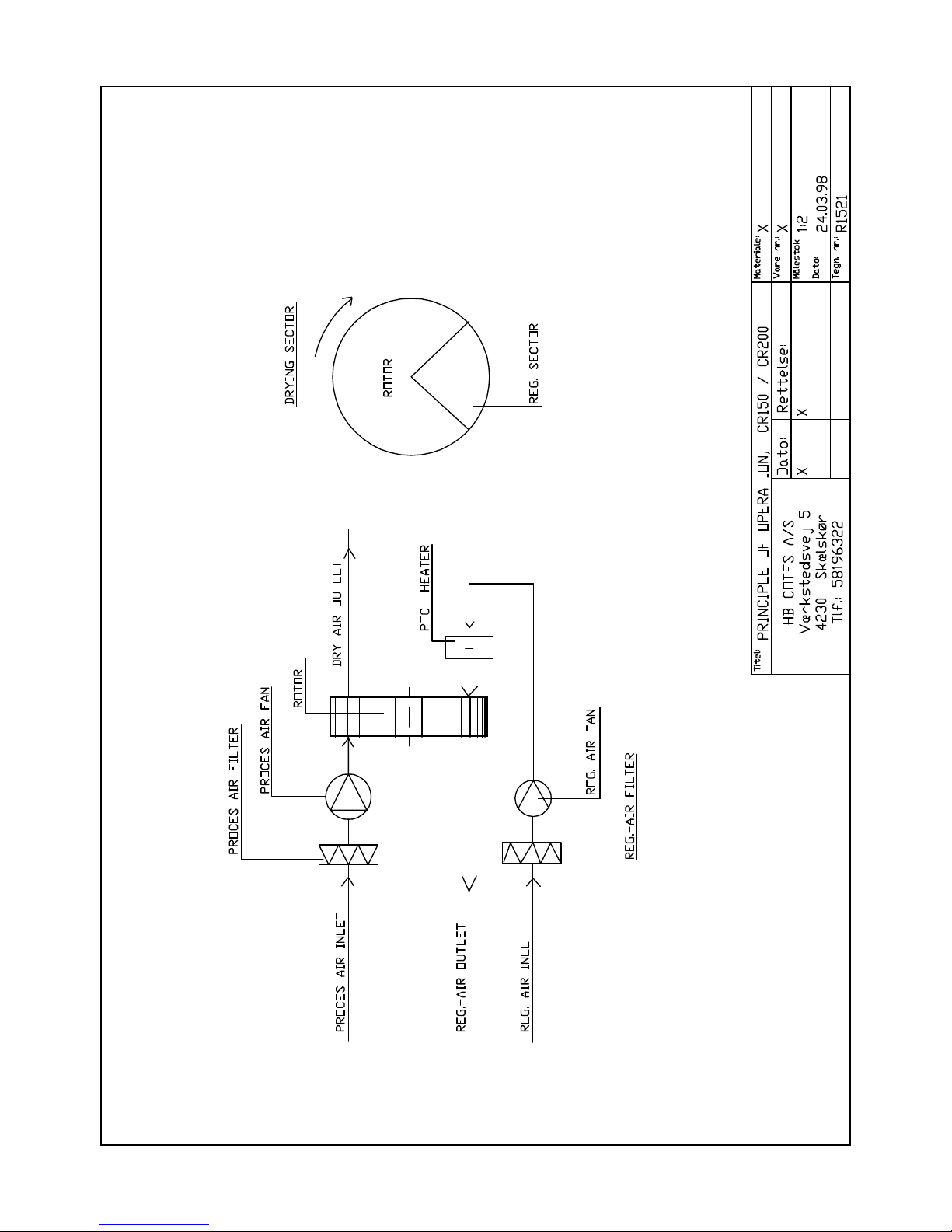
The dehumidifier removes water from an airflow through, and
the removed water is carried away from the dehumidifier with
the regeneration air (henceforward called reg.-air).
Water adsorption and -extraction takes place in an rotor made
of water resistant silica gel.
The air flows in the dehumidifier divides the rotor in two
parts : drying part and reg.-part.
Two separate air flows goes through the rotor as this:
- the main air (moist air inlet) goes through the drying
part, and leaves the dehumidifier as dry air
- the reg.-air coming from the outside to the reg.air fan,
through the internal hose to the electric PTC- heater and
will be heated to 130C (at 20C inlet).
Going through the reg.-part this energy will be used for
evaporation of the adsorbed water. The water vapours and
the reg.- air now leaves the dehumidifier through the reg.
- air outlet (see page 2, fig. 2).
The two air flows are fixed and the rotor turns - this gives
an automatic process of simultaneous water adsorption and wa-
ter extraction.
The inlet conditions of the air to be dried, determines how
much water the dehumidifier will remove.
On page 8 the capacity diagram shows how much water will be
removed per kg air going through.
(shown in the diagram R617)
- inlet air conditions 20C, 60 %RH, gives water content 8,7
g/kg
- the diagram shows then dry air condition of X= 3,7 g/kg
- removed per kg air is then: 8,7 - 3,7 = 5,0 g/kg
Dry air flow is nominal 200 m3/h = (x 1,2) = 240 kg/h
Capacity, removed water per hour = 240 x 5,0 = 1200 g/h
= 28,8kg/day
- at 230V.
The temperature of the dry air is higher than for the inlet
air. This is caused by the evaporation heat release and heat
gain from the rotor. The temperature is shown to be 41C.
1. PRINCIPLE OF OPERATION.
CAPACITY DIAGRAM R617 (page 8 ):
Example:
Capacity CR200 at this condition:


Page 3
Dehumidifiers in the CR range are used for dehumidification
of ambient air at normal atmospheric pressure. This can be
an installation for moisture control in an unheated store
room, in a water work building, production room for hygro-
scopic materials... - with the dehumidifier in a separate
installation.
The dehumidifier also can be used as a part of a bigger air
treatment system. Here the dehumidifier often will be placed
in a by-pass to the main system.
In this case the pressure in the main system wil influence
the dehumidifier - and your supplier must be contacted, as
this can influence the capacity of the dehumidifier.
Normally the dehumidifier will be placed in a wall bracket
1-1,5 m above the floor. The dehumidifier should always be
placed horizontal, resting on the four pcs. rubber supports.
The air to the dehumidifier and the air in the room in which
the dehumidifier is installed must be free from oil vapours,
exhaust gases, solvents or other explosive components and
should be free from pollution from solid particles.
- max. humidity ...................... 100 %RH
- max. temperature ................... 35C
- max./min. pressure ................. ambient +/- 300Pa
2. APPLICATIONS.
For air to the dehumidifier the following limit values
must be respected :
The CR range is for indoor, stationary installations.
Should not be placed in rooms with possibility for free wa-
ter on the cabinet.


Page 5
Dry air, free blowing ............ : 290 m3/h
Dry air, nominal ................ : 200 m3/h
Reg.-air, nominal ................ : 65 m3/h
External pressure, dry air (at 160): 160 Pa
External pressure, reg.-air (at 50): 150 Pa
Capacity at 20C, 60%RH ........... : 28 kg/day
(see capacity diagram, page 8) at 230V
Electric heater .................. : 2200 W
Power consumption, electric heater
at nominal conditions, 8,0A....... : 1840 W (230V)
Process air fan................... : 130 W (230V)
Reg.-air fan ................... : 84 W (230V)
Motor for gear ................... : 5 W (230V)
Nominal power consumption ........ : 2059 W
Voltage .......................... : 220-230V (1N+PE)
External fuses ................... : 10 A
Rotor ............................ : Silica gel, Ø300/50
Rotations of rotor ............... : 21 rph
Gear, (Saia) ..................... : J30S
Drive belt ....................... : Ø6/1070
Pulley ........................... : SPZ 63-1
L x W x H ........................ : 615x440x420 mm.
(see drawing R2126)
Weight ........................... : 29 kg
4. TECHNICAL DATA, SPECIFICATIONS CR200.
FURTHER SPECIFICATIONS:
DIMENSIONS:


Page 7
1 1 121109 Connection for reg.outlet, ø80
3 1 123001 Cabinet back plate
4 1 123003 Filter & fan Box
5 1 Cover for filter
6 1 123002 Cabinet, top plate
7 1 127004 Pulley SPZ63-1
8 1 132103 Drive belt Ø6/1050
9 1 110412 Gear, Saia J30S
10 1 110400 Motor for gear
11 1 111833 relay for 11p socket
12 1 Internal terminals
13 1 110000 Am-meter 10/50A
14 1 External terminals
15 1 112003 Hour-counter
16 1 110215 Selector switch, man/0/auto
17 1 112300 Power line filter
18 1 121183 Internal dividing plate
19 1 122605 Cover for heating elements
20 1 111454 PTC-heating element 6/22, first
22 1 111451 PTC-heating element 9/22, second
23 1 121183 Base for electric heaters
24 4 120051 Distance bolt ø12/70,4
25 1 124055 Rotor PPS ø300/50
27 1 123000 Cabinet
28 1 130601 Flex. hose ø80
29 4 132000 Shock absorbers
30 1 13o217 Filter cassette for process air*)
31 1 111660 Process air fan
32 1 130217 Filter Cassette for reg. air*)
33 1 111773 Reg.- air fan
34 1 110600 El-box
36 1 120712 connection for dry air ø100
37 1 121150 Dividing plate, fixed
38 2 131001 Teflon ring ø306
40 1 120050 Rotor shaft ø20/70,2
41 1 121100 Dividing plate, back, removable
42 2 131005 Teflon disc ø60
* filter Cassette AM-AIR-300, 180x180x48 EU4
4. COMPONENTS DIAGRAM, CR200.
(ref. to drawing R2127)
POS PCS. STOCK.NO DESCRIPTION.


Page 11
R2223 .. : Electric diagram
R2224 .. : Wiring in cabinet
SA1 110215: Selector switch, Manual, 0, Automatic.
Sälzer P220-61025E219M. 20A.
KT1 111833: Relay, Finder 60.13, 230V/50, 10A (AC1)
111851: Finder socket 90.73 for relay and timer
111822: Finder timer 86.60, delay 30S
M3 110400: Motor for gear, Saia UFR40.230
110412 Gear, Saia J30S
110430 Cap. 0,22 MYF
M1 111661: Process air fan, EBM G2E140-PL40-17, 230V/50
130W
111621 Cap. 2 MYF
M2 111773: Reg. air fan, GE120-2b, 230V/50, 84W
111620 Cap. 1,5 MYF
E1 111451: Electric heater, PTC-type. 9/22, 220-240V
E2 111455: Electric heater, PTC type, 6/22, 220-240V
E3 111460: Electric heater, 230V, 10W
KT2 111850: Relay on delay (gear motor and reg.air fan)
set for 1 min., Saia KOL312H7MRVPNOO
P3 110000: Am.meter, 230V, 10/50A. Deif type EQ48.
P2 112003: Hour counter, 230V. Müller type BW4028
P1 112300: Power line filter, 10VV1, 10A/230V
ST1 111205: Thermostat, EGO 75-10K, manual reset. (75C).
The PTC type electric heater is only functioning when air
flows through. This is the reason why no thermostats or
thermostatic switch is installed, as the function of these
components will be regulation of the energy for the electric
heater.
The dehumidifier is prepared for external regulation by a
humidistat. Therefore terminals for this connection is pla-
ced into the connection box placed on the front plate of
the dehumidifier, next to the dry air outlet. The terminals
is 6 & 7. In the connection box the terminals for power-
connection is placed too (U1,N,PE).
7.4 Electric components CR200.
7.5 Regulation by a humidistat.
Refers to electric diagrams:
THE INSTALLED ELECTRIC HEATER :
WARNING : DO NOT TOUCH THE ELECTRIC HEATER WHEN SWITCHED
ON, AS IT IS AN UNINSULATED LIVE WIRE.

Page 12
The terminals 6 & 7 are shunted at delivery. This shunt is
to be removed and the terminals for the humidistat connec-
ted.
At operating with connected humidistat, the selector switch
should be in position "automatic".
The humidistat should be approved for 230V/10A (ex. our
Jumo Compact spec., stock no. 140510).
The dehumidifier CR200 is connected 230V, 1N+PE. Connection
to the terminals U1,N,PE, placed into the outside connec-
tion box on the front of the dehumidifier.
Power consumption is 2,05 KW - to be fused by 10A.
The electric heater is 230V, 2200W and the external instal-
lation should be made for this.
The energy consumption of the PTC-heater is depending of the
air passing through.
At the nominal reg.- air flow of 65 m3/h the energy consump-
tion of the heater is 1840W, (= indication of 8,0A on the
am-meter at 230V).
The airflow and the energy consumption is regulated on the
damper delivered in our standard reg.- duct system (option,
see page 19, drawing R2232).
NOTICE: the energy consumption of the electric heater starts
up in to steps, second step after 30Sec.
Electric connection of humidistat, see 7.5 above.
The dehumidifier should be installed indoor, placed on a
wall bracket or some other horizontal basis. It should be
placed on the four pcs rubber supports underneath the ca-
binet.
8.1 The main air to be dried is normally taken from the
room, and through the main air filter on the back pla-
te.
As standard the dehumidifier is delivered with filter /
filter frame, but optional plate with Ø160 connection
for inlet air can be supplied.
As standard the dehumidifier is delivered with filter
for the reg.air, and a connector for Ø125 ducting.
7.6 Electric connection.
SUBJECT : POWER CONSUMPTION & AIRFLOWS.
CONNECTION OF DUCTS :
FREQUENT START/STOP ON THE SELECTOR SWITCH SHOULD BE
AVOIDED, AS IT CAN DAMAGE THE IN BUILD RELAY, OR THE
EXTERNAL FUSES.
8. INSTALLATION.


Page 14
Reg.-air inlet should be fitted with duct Ø80 or bigger.
Reg.-air outlet should be fitted with duct Ø80 and
damper - installed draining away from the dehumidifier
to allow the water to run free.
If this is not possible, a hole Ø4 mm should be drilled
underneath at the lowest part of the duct.
Reg.air ducts (option), see drawing page 19.
Dry air outlet can be connected Ø100mm ducts.
In general ducts of the same size as placed on the dehumidi-
fier should be used - or bigger.
If the dehumidifier should be connected to another air
treatment system, the air pressure of this system will
influence the dehumidifier. You should then contact
your supplier before installation for advice.
See fan curves, page 13.
Before starting-up the dehumidifier, check that all
electric connections are made correctly.
If this is OK, just connect the plug into the electric
switch, and switch on.
- manual = continuous operation
- 0 = switched off
- automatic = operation with connected humidistat
At starting up, select the position for the chosen
operation mode.
If it does not start-up, it can be caused by the humidi-
stat. If the actual %RH is lower than wanted, the humi-
distat is broken.
This can be checked like this:
- adjust the humidistat to 20 %RH, and the dehumidifier
should then be operating
- adjust the humidistat to 90 %RH, and the dehumidifier
should stop operating.
The two PTC electric heaters starts in two steps. At
switching on the dehumidifier the heater E1 starts up
immidiately. This is visible on the am-meter which in-
dicates up to 10A in the first seconds, and stabilise
at app. 5A.
30 sec. later the second heater, E2, is switched on. On
the am-meter is then indicated up to 16A and should
stabilise on 8A in 6-8 sec.
NB :
10. COMMISIONING CR200,
10.1 ELECTRIC.
The selector switch has three positions:
Especially at "automatic":
10.2 ELECTRONIC TIMER, KT1.

Page 15
The amps is adjusted on the damper in the reg.air inlet
ducts (see drawing R2232, page 19). Adjusted value must
be 8,0A.
If stabilised at a higher value, the damper must be clo-
sed until 8A is indicated.
If stabilised at a lower value, the damper must be ope-
ned until 8A is indicated.
The relay KT2 (on delay, 1 min.,) controls the gear motor
and the reg.air fan. This means that they will continue
operating even that the dehumidifier is stopped by a
connected hygrostat or on the selector switch.
This continued operation cools the electric heater and
at the same time the evaporated moisture from the warm
rotor material in the reg.section is ventilated out of the
dehumidifier.
It is important that the dehumidifier is stopped as de-
scribed above and this delay for the gear motor and reg.-
air fan is active. If not, the moisture might cause
short circuit in the PTC heater at restart.
Air flows should be adjusted.
The dry air flow should be adjusted for the nominal 200
m3/h for obtaining data from the capacity diagram.
If the installation is normal dehumidification of a
room for 50 - 100 %RF it is acceptable that the dehumi-
fier is free blowing (without adjustment).
If lower dew points are wanted, you need to adjust the
dry air flow.
- the dry air flow can be adjusted by the optional dam-
per in the dry air outlet. If only a short duct is
installed, the airflow should be reduced on the
damper to obtain the nominal 200 m3/h.
- the reg.- air flow can be adjusted on the damper in
the reg.-air outlet (option). Start-up with the damper
in the closed position, opening until the Am.meter
indicates 8,0A (Switch-on current is 16A, 6 sec., see
above, 10.2, electronic timer KST1).
Reg.-air flow always has to be controlled. Check the
reg.-duct for allowing free blowing of the reg.-air.
Check that the reg.-air duct is installed draining from
the dehumidifier.
With the electrical settings and air flows adjusted, the
dehumidifier will then operate automatically by means of
the internal control- and safety functions - controlled
by an external humidistat.
10.3 STOP OF DEHUMIDIFIER.
10.4 Air flows.
How to adjust the air flows:
IMPORTANT :
Am-meter reading below 7,0A might damage the rotor and
the PTC heater.

Page 16
Dehumidifier CR200 only needs a minimum of maintenance.
All components are service free, which means no lubrication
or adjustment.
Only three things should be checked under normal operati-
on:
- air filters should be checked or replaced at least every
3 mth.- depending on the pollution of the air.
2 x cassette 180x180x48mm, stock no. 130217
- the rotation of the rotor should be checked once a
month.
- the power consumption of the electric heater should be
checked often (reading 8,0A on the Am.meter).
If the rotor rotates during operation, and the energy con-
sumption of the electric heater shows app. 8,0A, you ca be
almost sure that the dehumidifier is operating at an opti-
mum.
We nevertheless recommend some periodic verification of
the entire dehumidifier, to see if all internal functions
are ok and checking of gaskets and moving parts for wear
and tear, capacity of the rotor and so on.
The periodic check once a year.
This will ensure that the capacity is on its maximum, and
thus wont waste any energy.
12.1 If the dehumidifier does not start when electric con-
nected, control the external fuse.
12.2 If the dehumidifier is not operating it is probably the
external humidistat which has broken.
This is a normal situation when the desired humidity is
obtained.
To check : adjust the humidistat for 20 %RH, and the
dehumidifier should start operating. Adjust again for
the desired humidity.
12.3 If the Am-reading is 0 (zero) during operation, the ther-
mostat ST1 might have broken. Check that the reg. air fan
is operating. Check that the after cooling function is ok.
If this is ok, push the button for manual resetting of
the thermostat (red button in front of the cabinet) and
the Am-reading should indicate the normal 8A.
11. MAINTENANCE.
12. TROUBLE SHOOTING.
Filters:
Rotation of the rotor can be checked through the hole in
the cabinet plate when the grey rubber plug is removed.
The rotor should then turn downwards.

Page 17
12.4 If the desired humidity is not obtained, the problem
can be the dehumidifier - or the other parts in the
total installation ( room tightness, humidistat...).
To verify this, check:
- rotation of rotor ?
- the dry air should be 15-20C warmer than the inlet
main air. If it is cold it could indicate that the
rotor is not turning caused by broken drive belt or
the motor has stopped.
- by hand feel the temperature of the reg. outlet air,
and feel the airflow. The temperature is depending on
the inlet conditions, but should be 40-60C.
The am-meter should indicate 8,0A - if less check the
filters.
If it is cold and Am.meter shows 0A, the electric
heater might need replacement.
Before opening the dehumidifier, make sure that the
electric power is switched off on the main switch.
When the top plate is removed these components are ac-
cessible for replacement (placed in the cabinet front
cover).
Remove the cabinet top plate, and the gear is visible on
the dividing plate.
The cabinet front cover must be removed too for easy
access to the motor and the gear. Notice that motor and
gear can be separated - by fault one motor or gear
has to be replaced.
Remove the cabinet top plate, and the fans are visible,
placed on the cabinet back cover.
Remove the screws of the fans through the filter frame
from the outside, and disconnect the wiring (power
supply to the fans9 at the connector placed close to
the fans.
Remove the small cover in the front of the dehumidi-
fier (drawing R2127, pos 19, page 6).
When the cover is removed, the PTC heaters are visible
and accessible for replacing.
13. SERVICE/REPAIR.
13.1 SAFETY INSTRUCTION.
13.2 REPLACING OF AM-METER, SELECTOR SWITCH, HOURCOUNTER.
13.3 REPLACING OF THE MOTOR FOR GEAR/GEAR.
13.4 REPLACING OF THE FANS.
13.5 REPLACING THE ELECTRIC HEATERS (PTC).

Page 18
Remove the top plate and the back cabinet plate.
For removing the back cabinet plate, at first unscrew
the reg.-connection from the plate. It is fixed by
4 pcs M5 screws each.
For removing the rotor, the rear dividing plate must be
removed at first. This is fixed by 4 pcs screws M5 for
distance bolts, one pcs M8 screw in the middle for the
shaft.
When the back dividing plate is removed, rotor, ga-
skets, shaft and timing belt can be removed if necessa-
ry.
The sound level is measured according to EN292-2, annex A.
" if the working is not specified, or cannot be specified,
the sound level should be measured in a distance of 1m
from the surface of the unit, and in a distance of 1,6m
from the floor or the frame"
The dehumidifier is during the measuring of the sound level
placed with the top plate 1m above the floor. Ducts for reg.
air is installed and led out of the room, and 2m dry air
duct Ø100 is installed too. The sound level is then measured
1m outside the cabinet, and 1,6m above the floor, and a
sound level of 58 dB(A) is measured.
13.6 REPLACING OF ROTOR, ROTORGASKETS, ROTORSHAFT, DRIVE-
BELT.
14. SOUND LEVEL.
MANUFACTURED BY :
HB COTES A/S
Værkstedsvej 5
DK-4230 Skælskør.
Phone +45 58 19 63 22
Fax +45 58 19 58 44
www.hbcotes.com

Table of contents
Other Cotes Dehumidifier manuals
Popular Dehumidifier manuals by other brands

Frigidaire
Frigidaire FFAD6022W1 user manual

emerio
emerio DH-122845.2 instruction manual

CKD
CKD GT9000WV Series instruction manual

Puredry
Puredry DESIGN SERIES PD 130LA instruction manual

Demargo
Demargo DM240NF Instructions for installation and operation

Polario
Polario MP20 Owner's manual & installation manual