Count Dyna-Cut User manual

DYNA-CUT
MANUAL
Martin Yale Industries, LLC.
251 Wedcor Avenue, Wabash, Indiana 46992
226600--563-0621 | Fax: 260-563
www.martinyale.com

DYNA-CUT 2
TABLE OF CONTENTS
Specifications
3
Safety
Procedures
4
Care and Maintenance
5
Component
Identification
6
Touch Screen Controller
7
Setting
Up Your Dyna-Cut
10
-Installing a Flexible Die
10
-Removing a Flexible Die
10
-Delivery Tray Installation
11
-Delivery Tray Sensor Setup
12
Setting Up the Automatic Feeder
13
-Loading the Feeder
13
-Setting the Air Channels
14
-Setting Table Height and Setting
14
Setting
Up the Paper Path
15
Setting Pressure on the Cylinder
16
Setting
Up Scrap Separator
17
Setting Delivery
Table
18

DYNA-CUT 3
SPECIFICATIONS
Net
Weight: 1000
*
Min.
Sheet Size
8 ½” x 11”*
Max
Sheet Size
14” x 20”
Max Sheet
Thickness
400 GSM*
Min Sheet Thickness
100 GSM*
Max
Speed 6000 Sheets an
Hour
Electrical Requirements and Specifications
Power Requirement: 110v, 50-60HZ, AC
Circuit Protection: 20 AMP Circuit Breaker
NOTE: Older buildings, overloaded lines, and bad grounds can
affect the operation of your Dyna-Cut. A dedicated line is best.
*NOTE: The Dyna-Cut is capable of handling many types of applications
above and beyond the standard specifications. It is possible to feed quite
a variety of jobs. However, the performance of the Dyna-Cut on these
special applications is directly related to the experience of the operator.

DYNA-CUT 4
SAFETY PROCEDURES
BEFORE USE:
•Read through the owner’s manual. Follow instructions CAREFULLY.
•NEVER use a wet area. Electric shock could occur.
•Use a GROUNDED outlet and a GROUNDED circuit. Do not use
undergrounded equipment on the same circuit.
•Always use a dedicated line. DO NOT use with line splitting surge
protector.
DURING USE:
•Keep fingers and hands away from all rotating parts.
•Keep cords clear of moving parts.
AFTER USE:
•Turn off machine at the power switch, then unplug the main
power cord. This will prevent damage to your machine by
power/voltage spikes.
•To unplug cords, always grasp the plug body, never pull on cords
to disconnect. Wire fatigue and possible shock could results from
improper disconnect procedures.
BE ALERT! BE CAREFUL!

DYNA-CUT 5
CARE AND MAINTENANCE
The Dyna-Cut is a precision machine. It is very important to keep it free of
excessive dust, dirt, and foreign matter. We recommend that you keep the
machine covered when not in use.
BEARINGS: The Dyna-Cut uses 2 different style bearings sealed roller
bearing and bronze bushings. Sealed roller bearings and are designed to
be self-lubricating, however dirt and dust can get into them causing
clogging and dirt build up. Bronze bushings need to be oiled on a regular
basis. The bronze bushings on this machine are located on the operator
side frame and have the perf shaft and exit shaft through them. There are
also 2 bushings located on the feed drive shaft. To oil these bronze
bushings run the machine in feed mode and add a few drops of oil just
inside the shaft collar that hold the shaft in place. Also add a few drops to
the inside of the machine so both sides of the bushing gets oil. It is
recommended to occasionally oil the sealed roller bearings under heavy
use.
REMOVEABLE SCREWS: When these show signs of wear or stripping,
replace as soon as possible. If these strip or hollow out they can be costly
to remove. If you do keep your FC114 AIR clean and in top condition, it
will give you years of service.
DYNA-CUT 6
COMPONENT IDENTIFICATION

DYNA-CUT 7
TOUCH SCREEN CONTROLLER
TOUCH SCREEN OPERATION
When the machine is turned on, the display may take up to 7 seconds for
the home screen to display. There is a screen saver that will turn the display
off if the machine is not touched within 30 minutes. The power light will
stay illuminated letting you know the machine is still on.
COUNT LOGO AND SERVICE ACCESS
If the logo is pressed a password screen is displayed. This is for factory and
service access only. This screen is for manufacturer use only. The password
is not given out.
DYNA-CUT 8
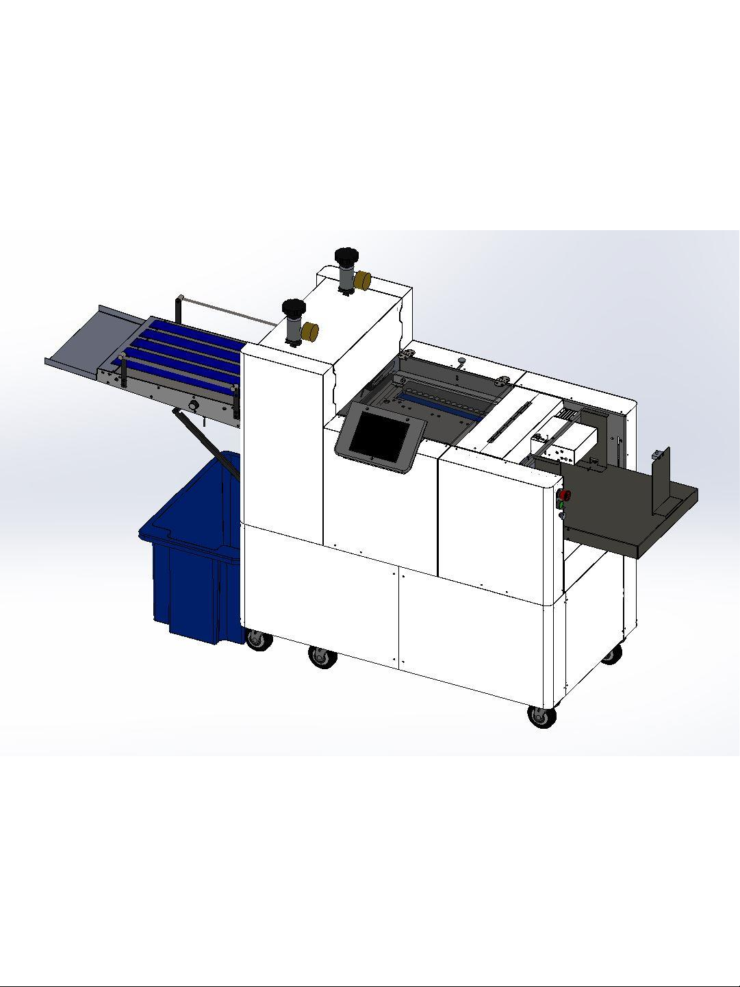
ELEVATOR CONTROLS
These control the feed platform where the paper is loaded. Auto up will raise the Elevator until
height sensor located in the Vacuum system is triggered. Up and Down arrows will raise and
lower the elevator while the button is pushed. Elevator Stop will stop the elevator if auto up has
been pushed.
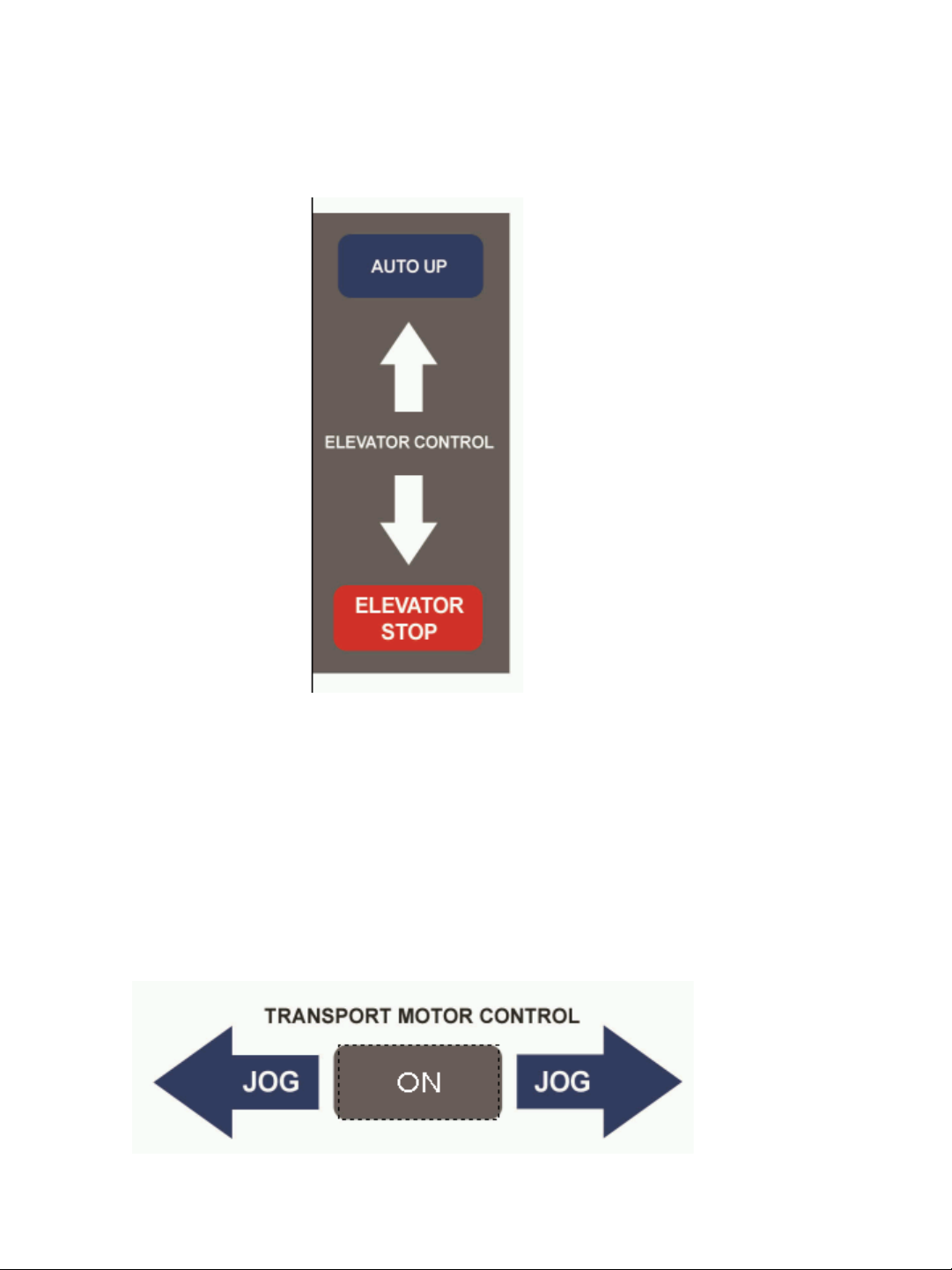
TRANSPORT MOTOR CONTROLS
Pressing the ON button will turn on the transport motor which will sync speed with the cylinders.
Jog will move paper forward or backwards on the Registration Table.

DYNA-CUT 9
CUT ADJUST CONTROLS
Use these controls to vertically shift cut on the paper. Each unit on the cut adjust is
a 0.10”. To shift the cut towards the top of the page use the “-” in order to shift the
cut towards the bottom of the page use “+”.
To adjust the side margins of the paper use the margin adjust knob. This will
horizontally shift the paper on the registration table. Turning the knob in the
decrease margin direction will make the margin on the page smaller while increase
margin direction will make the margin on the page larger.
In order to adjust the skew on the sheet use the knob located directly in front of
the marble rack.
Margin Adjust Knob
Skew Adjust Knob

DYNA-CUT 10
SETTING UP YOUR DYNA-CUT
INSTALLING A FLEXABLE DIE
1. Take the pressure off of the dies using the hydra jacks this
will make the cylinder easier to spin.
2. Rotate the cylinder so that the 3 threaded guide holes are
facing you.
3. Install the guild pins these will help line up the die.
4. Place die one evenly until the leading edge is flat against
the magnetic cylinder.
5. Remove the guild pins you may need to use an Allen tool in
order to remove.
6. Rotate the cylinder forward by hand this will pull the die
onto the magnetic cylinder once it is fully on the cylinder in
sure that the lines on the front and rear of the die line up
this will show if there is any skew on the die install.
REMOVING A FLEXABLE DIE
1. Take the pressure off of the dies using the hydra jacks this
will make the cylinder easier to spin.
2. Rotate the cylinder so that the seam of the die is facing you
3. Use the die removal tool. Slide it under one corner of the
die pull the die off of the magnetic cylinder. Carefully begin
to pull the die off of the cylinder. Note that the sides and
knife edges of the die are very sharp handle with care
always move slowly and make sure you have steady grip.
Table of contents
Popular Cutter manuals by other brands

Milwaukee
Milwaukee HEAVY DUTY M12 FCOT Original instructions

Makita
Makita DCS552 instruction manual

SignWarehouse.com
SignWarehouse.com Bobcat BA-60 user manual

Makita
Makita 4112HS instruction manual

GEISMAR STUMEC
GEISMAR STUMEC MTZ 350S manual

Hitachi
Hitachi CM 4SB2 Safety instructions and instruction manual


