Courtyard TCS46GL User manual

PAGE 1 OF 7
ASSEMBLY INSTRUCTIONS
ATTENTION: THIS PRODUCT IS NOT FOR COMMERCIAL USE INTENDED FOR RESIDENTIAL USE ONLY.
TCS46GL
COURTYARD CREATIONS INC.
Use the correct bolts as indicated. Do not tighten any of the bolts until is completely assembled.
Do not sit or stand on this table.
Keep children away during assembly. This item contains small parts which can be swallowed by children.
Do not use indoors or inside any enclosure.
Retain these assembly instructions for future reference.
Installer - Please leave these instructions with the owner.
Quote the following FQC NO. when contacting the service center.
SERVICE CENTER TOLL FREE NO.
TEL: 1-877-539-7436
FAX: 1-877-539-7439
!
!
!
!
!
!
!
WARNING: For Outdoor Use Only
!
Warning: If the information in this manual is not followed exactly, a fire or explosion may
result causing property damage, personal injury, or loss of life.
• Do not store or use gasoline or other flammable vapors and liquids in the vicinity
of this or any other appliance.
• An LP-cylinder not connected for use shall not be stored in the vicinity of this or
any other appliance.
DANGER: If you smell gas:
1. Shut off gas to the appliance .
2. Extinguish any open flame.
3. If odor continues, keep away from the appliance and immediately call your gas
supplier or fire department.
• Installation and service must be performed by a qualified installer, service agent,
or gas supplier.
Warning: Improper installation, adjustment, alteration, service, or maintenance can cause
injury or property damage. Read the installation, operating, and maintenance
instructions thoroughly before installing or servicing this equipment.
DANGER CARBON MONOXIDE HAZARD
This appliance can produce carbon monoxide
which has no odor.
Using it in an enclosed space can kill you.
Never use this appliance in an enclosed space
such as a camper, tent, car, or home.
!
!
!
!

PAGE 2 OF 7
This appliance has been tested to and complies
with the ANSIZ21.97 - 2010 and CGA CR97-003.
The installation must conform to local codes or in
the absence of local codes to the National Fuel
Gas Code, ANSIZ223.1 and CAN/CGA-B149.2.
Keep the appliance area clear and free from
combustible materials, gasoline, and other
flammable vapors and liquids.
Solid Fuels should not be burned in this Gas
Fireplace.
Inspect the hose before each use of the appliance.
The hose assembly must be replaced prior to the
appliance being put into operation if there is
evidence of excessive abrasion, wear, or if the
hose is damaged. The replacement hose assembly
is specified in this manual.
The burner must be inspected before each use.
The burner must be replaced prior to the appliance
being put into operation if it is evident that the
burner is damaged. The replacement burner is
specified in this manual.
The burner should always be cleaned:
Disconnect it from the appliance, use a cleaner to
remove blockages attached on the ports and drain
the blockages from the gas inlet. A high pressured
stream of water may also be used.
Do not use this appliance if any part has been
under water. Immediately call a qualified service
technician to inspect the appliance and to replace
any part of the control system and any gas
control which has been under water.
This appliance is for outdoor use only in a
well-ventilated space and should not be used in
a building, garage, or any other enclosed area.
other cylinders may be acceptable for use with the
appliance provided they are compatible with the
appliance retention means and accompanied by
illustration(s) depicting the cylinder mounted to the
appliance utilizing the cylinder retention means and
the point of contact between the cylinder and the
retention means.The cylinder should be 12 inches
in diameter and 18 inches high. The capacity is
20lbs of propane.
If the appliance is not in use, the gas must be turned
off at the supply cylinder.
Storage of an appliance indoors is permissible only
if the cylinder is disconnected and removed from the
appliance.
Cylinders must be stored outdoors in a well-ventilated
area out of children’s reach.
Disconnected cylinders must have a dust cap
secured at the end of the valve and can not be stored
in a building, garage, or any other enclosed area.
The pressure regulator and hose assembly supplied
with this appliance must be used. Replacement
pressure regulators and hose assemblies must be
the ones specified in this manual.
The cylinder supply system must be arranged for
vapor withdrawal.
The cylinder used must include a collar to protect
the cylinder valve.
The Procedure for Checking for Gas Leaks:
Never test for leaks with a flame. Prior to first use, at
the beginning of each season, or every time your LP
gas tank is changed, you must check for gas leaks.
Follow these three steps:
1. Make a soap solution by mixing one part liquid
detergent and one part water.
2. Make sure the burner is off and then turn gas on at
source.
3. Apply the soap solution to all gas connections,
especially to the inlet/manifold pressure tap on the
gas valve after reading the pressure. Bubbles will
appear in the soap solution if the gas connections
are not properly sealed. If you have a gas leak,
tighten gas connections, turn off the gas at the
source, disconnect the fuel line from your fireplace
and call 1-877-539-7436 for repair assistance.
WARNING
!
WARNING
!
WARNING
!
WARNING
!
The LP-gas supply cylinder to be used must be:
1. Constructed and marked in accordance with the
U.S. Department of Transportation (D.O.T.)
Specifications for LP-Gas Cylinders, or the
Standard for Cylinders, Spheres and Tubes for
Transportation of Dangerous Goods; and
Commission, CAN/CSA-B339 as applicable;
2. Provided with a listed overfilling prevention device;
and;
3. Provided with a cylinder connection device
compatible with the connection for the appliance.

PAGE 3 OF 7
#14 BOLT M6*40
40
3
2
22
14
17
1
FIGURE 1
Note:
The labels marked “2” and “3” on the frames should
coincide with Figure 1 to ensure proper assembly.
Attention:
Make sure that each bolt needed for all steps matches
the corresponding figure to ensure proper assembly.
Step 1:
Fasten the right frame (#2) and the left frame (#3) to the
rear frame (#1) by using bolts (#14) and washers (#17).
Keep the bolts loose. See Figure 1.
Note: Parts come in more than one carton.
Before assembly, open all of the packaged cartons.
Lay out all of the parts on a level, non-abrasive
surface. Open the hardware kit for all of the nuts,
bolts, and washers. Make sure that you have all of
the parts listed. If any parts are missing or damaged,
call the help line at 1-877-539-7436 before returning
this item to the store.
LAVA ROCKS
HEX.KEY WRENCH 10MM
HEX.KEY WRENCH 4MM
BOLT CAP
NUT M6
NUT M6
WASHER d6.5*D10*1.6
WASHER d6.5*D13*1.0
WASHER d6.5*D13*1.0
HANDLE
BOLT M6*14
BOLT M6*40
COVER
FUEL SUPPLY HOSE
TILE
UPPER CONNECTOR
LOWER CONNECTOR
TANK FASTENER
TANK SUPPORT
ASSEMBLY
TABLE TOP
FRONT DOOR
CROSS BRACE
LEFT FRAME
RIGHT FRAME
REAR FRAME
TGS46GT-CS05
17KAA0101----Y4
17KAC3101----Y3
18000337004
17D02A030301-Y6
17D02D030302-Y5
17FD05040301-Y5
17FD05020601-Y5
17FA05040301-Y4
17C33A0722001Y4
17XD8303-----Y5
17C33A0714001Y4
17XA4907
17XY9701
13C??B30008001
17XAA103
17TAN00030
17XA0486-----Y6
TCS46GY-CS07
TCS46GL-CS04
TCS46GW-CS05
62TGS46GTQ101
TCS46GL-CS03
TCS46GL-CS02
TCS46GL-CS01
1
1
1
16
2
1
1
2
18
12
1
4
1
24
25
23
22
20
21
19
18
17
16
15
14
13
1
16
1
1
1
1
1
1
1
1
1
1
12
11
9
10
8
7
6
5
4
3
2
Q’TY
1
PARTMATERIAL CODE
PART
NO.
PARTS LIST

#15 BOLT M6*14
5
2
3
5
10
17
15
22
5
10
FIGURE 5
Note:
1) Please close the front door to
ensure proper assembly.
See Illustration A.
2) When moving the fire pit, please
ensure that the front door is
closed.
PAGE 4 OF 7
Step 5:
Insert the upper connector (#10) marked “F”, into the
top holes of the front door (#5). Fasten the upper
connector (#10) to the left frame (#3) by using bolt
(#15) and washer (#17). See Figure 5.
Note:
The lower connector (#9) is marked with an “E”.
#15 BOLT M6*14
23
9
5
5
3
E
9
17
15
22
3
2
FIGURE 4
Step 4:
Fasten the lower connector (#9) to the corner of the
bottom rim of the left frame (#3) by using bolt (#15)
and washer (#17). Then, insert the front door (#5) in
to the connector tab of the lower connector (#9).
See Figure 4.
Note:
The wheels attached on the tank support assembly (#7)
should be facing towards the outside.
Step 3:
Fasten the tank support assembly (#7) to the front door
(#5) by using bolts (#15) and washers (#17). Insert the
tank fastener (#8) in to the tabs on the front door (#5)
and fasten them together by using washers (#17) and
nuts (#20). See Figure 3.
Step 2:
Insert both ends of the cross brace (#4) into the bottom
grooves of the right and left frames (#2 and #3) from top
to bottom. Fasten them together by using bolts (#15)
and washers (#17). Completely tighten all of the bolts.
See Figure 2.
#15 BOLT M6*14
7
22 22
17
15 15
17
7
8
5
20
17
The tab
8
FIGURE 3
22 15 17
3
4
3
4
2
1
FIGURE 2
14 14
14
14
#15 BOLT M6*14
Note:
The labeled arrow marks on the cross brace (#4) should
coincide with Figure 2 to ensure proper assembly.

PAGE 5 OF 7
Step 9:
Attach the fuel supply hose (#12) to the tank by
rotating clockwise to its connector. See Figure 9.
Step 8:
Open the front door (#5), place the tank into the tank
support assembly (#7) and through the tank fastener
(#8). See Figure 8.
Caution:
Tank must
face this way.
FIGURE 9
7
8
5
FIGURE 8
Step 7:
Place the tiles (#11) on to the table top (#6).
See Figure 7.
Note:
The igniter valve should be facing the front left side
of the fire pit.
Note:
If any EVA foams on the table top (#6) are missing, there
are extra EVA foams in the hardware kit. See Illustration B.
Step 6:
Place the table top (#6) on to the frame assembly.
Fasten them together by using bolts (#15) and
washers (#17). Completely tighten all of the bolts
and cover them with bolt caps (#22). See Figure 6.
6
11
FIGURE 7
25
Igniter
Valve
3
6
17
15
22
FIGURE 6
14
#15 BOLT M6*14
B
rotate
clockwise
12

FIGURE 10
FIGURE 12
burner system
hose
Note:
When closing the door,
ensure that the distance
between the hose and
the burner system is
more than 2 inches.
FIGURE 11
Step 10:
Attach the other end of the fuel supply hose (#12) to
the igniter valve. See Fig 10-1, Fig 10-2, Fig 10-3, and
Fig 10-4.
Fig 10-1 Fig 10-2 Fig 10-3 Fig 10-4
fire shield
Note:
The fire shield on the
burner system must be
exposed.
Note:
The lava rocks can not be
exposed over top of the
steel cover surface.
Step 11:
Place the lava rocks (#25) into the steel cover.
See Figure 11.
Step 12:
Fasten the handle (#16) to the cover (#13) by using
washers (#18 and #19) and nut (#21). Place the
assembled cover (#13) on to the table top (#6) to
cover the lava rock set. See Figure 12.
Note:
In order to protect the burner system, when
the fire is not in use and on rainy days, the
cover should be used to protect the fire bowl.
PAGE 6 OF 7
613
16
18
18
19
21
SPECIFIC WARNINGS:
1) Both children and adults should be aware of the hazards of high surface temperatures and should keep their
distance in order to avoid burns and ignition of clothing.
2) Children should be under adult supervision when in the vicinity of this appliance.
3) Clothing or any other flammable materials should not be hung from or near this appliance.
4) Any guard or protective device removed for servicing the appliance must be replaced prior to use.
5) Installation and repair should be done by a qualified person. The appliance should be inspected before use
and at least annually by a qualified service technician. Frequent cleaning may be required. It is imperative that
the control compartment, burners, and circulating air passageways of the appliance be kept clean at all times.
25
The store where you made your purchase
does not stock parts for this item.
If you need parts,
whether they are missing or damaged,
STOP!
MissingAPart?
No Need To Go Back To
The Store
Call us between 9:00 AM and 4:30 PM
Eastern Time Monday through Friday
Call Toll Free:
TEL: 1-877-539-7436
FAX: 1-877-539-7439
READ THESE INSTRUCTIONS COMPLETELY BEFORE STARTING ASSEMBLY
SEPARATE AND IDENTIFY ALL PARTS, MAKING SURE THAT YOU
HAVE ALL OF THEPARTSLISTED.
IF YOU DO NOTLOCATE ALL OF THE PARTS LISTED, INSPECT THE
PACKING MATERIAL FOR SMALL PARTSTHAT MAYHAVEBECOME
SEPARATED DURING SHIPMENT.
IF YOU EXPERIENCEANYDIFFICULTYDURING ASSEMBLYOR IF ANY
PARTS ARE MISSING OR DAMAGED,CALL THE HELP LINE AT
1-877-539-7436 BEFORERETURNING THIS ITEM TO THESTORE.
PROVIDE THEFOLLOWING INFORMATION WHEN CALLING:
1-MODEL NUMBER OF THEPRODUCT.
2-PARTNUMBER AND MATERIAL CODE OF THE PARTFROM THE PARTS
LIST.
MOST PROBLEMSCAN BERESOLVED WITHOUT RETURNING THIS
PRODUCT TO THERETAILER.

PAGE 7 OF 7
Please read the following switch usage instruction for lighting and to
extinguish:
Switch Usage Instruction
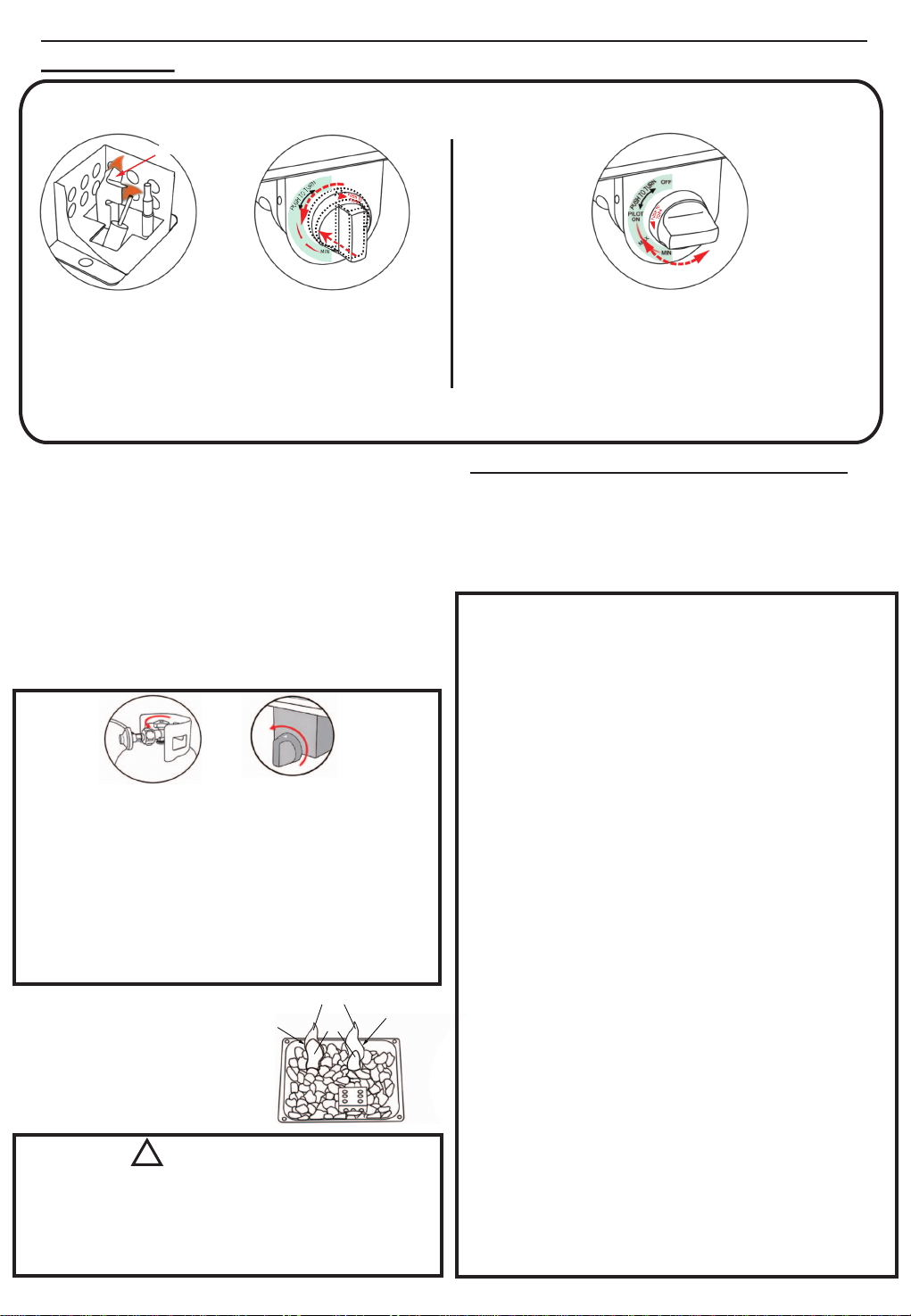
Step 1: Lighting :
To ignite, push the “T” shaped switch in and rotate
counterclockwise. Release the switch after lighting
and when the flame is stable.
Step 2: Adjusting :
When lit, let the “T” shaped switch pop up, wait 5
seconds, and rotate the switch counter-clockwise
to adjust the flame size.
Note: To extinguish the flame, push the “T” shaped switch in and rotate clockwise.
OFF
PILOT
ON
MAX
MIN
Main Flame
Yellow
Blue Incorrect
Flame
correct
Flame
Very hot while in operation!
Never lean over the fireplace while in use.
Do not touch tile of spark guard while the fire pit is in operation, wait until
the fire pit has cooled down after use.
Failure to comply with these instructions may result in
serious bodily injury.
Instructions for lighting and shutting down
appliance:
1. Read the instructions before lighting and shutting down the appliance.
2. Turn the Tee handle to OFF position.
3. Fully open the gas control valve.
4. Push and rotate the tee handle counter-clockwise, hold it at the pilot
position for at least 20 seconds until the thermocouple is hot. Do not
stand with your head or arms over the fire pit.
5. If ignition of the pilot does not occur in 5 seconds, turn off the tee handle,
wait for 5 minutes, and then repeat the lighting procedure.
6. Keep rotating the tee handle slowly to open the burner.
7. Rotate the tee handle clockwise to shut down the fire pit.
Step 3 Step 4
CARE AND MAITENANCE:
1. Do not use aerosol polish or any other flammable material to clean the
burner while it is in use.
2. Inspect and clean the burner regularly. Use a wire bristle brush to clean
the burner surface. A straightened paper clip is useful to remove debris or
rust from the small burner ports.
3. Wash frame parts with mild soap and water, rinse thoroughly, and dry
frame completely. Do not use bleach, acid, or any other solvents on the
frame parts.
4. Please inspect and tighten all of the bolts and fasteners on a regular basis
to ensure proper performance and safety of your outdoor firepit.
5. When not in use, we recommend that it be stored in a dry and secure area.
Always disconnect the LP gas tank first and store it safely outside.
6. The minimum clearance from the sides and rear of unit to adjacent
combustible construction: 2 feet from sides and 2 feet from rear.
WARNING
!
Use of your fire pit causes carbon
residue to build up on the lava rocks
inhibiting the airflow and leading to
a more yellow flame. Stir up the lava
rocks regularly to remove these
deposits and maintain a blue flame.
LP GAS SAFETY INSTRUCTIONS
This outdoor fire pit is not intended to be installed in or on
recreational vehicles and/or boats.
1. Never connect an unregulated LP gas tank to your fire pit. The
gas regulator assembly supplied with your fire pit is adjusted to
have an outlet pressure of 11’’ water column (W.C.) for
connection to an LP gas tank.
2. Only use the regulator with hose assembly supplied with your
fire pit. A replacement regulator with hose assembly must be the
one specified in this manual.
3. Have your LP gas tank filled by a reputable propane gas dealer
and visually inspected and re-qualified at each filling.
4. Never fill the gas tank beyond 80 percent full. Have your
propane gas dealer check the release valve after every filling to
ensure that it remains free of defects.
5. Always keep LP gas tanks in an upright position. Do not store
(or use) gasoline or other flammable vapors and liquids in the
vicinity of this appliance.
6. LP gas tanks not connected for use must NOT be stored inside
of the fire pit or in the vicinity of this or any other gas appliance.
7. Do not subject the LP gas tank to excessive heat. Never store
an LP gas tank in a garage or any other indoor location.Always
disconnect the LP gas tank first and store it safely outside.
8. LP gas tanks must be stored outdoors in a well-ventilated area
and out of children’s reach. Disconnected LP gas tanks must not
be stored in a building, garage, or any other enclosed area.
9. When your fire pit is not in use, the gas must be turned off at the
gas tank.
10. The regulator with hose assembly should be inspected before
each use of the fire pit. If there is excessive wear, any abrasions,
or if the hose is cut, it must be replaced prior to use of the fire
pit.
11. Keep the gas regulator hose away from hot surfaces. Avoid
unnecessary twisting of the hose. Visually inspect the hose for
cuts, cracks, excessive wear, or damage prior to each use of
the fire pit. If the hose is damaged DO NOT use the fire pit.
Call 1-877-539-7436 for an authorized replacement hose.
12. Never allow children to play near your fire pit.
Maximum Inlet Pressure 250 psig
Minimum Inlet Pressure 25 psig
Manifold Pressure 11 inches W.C.
Gas Rating 37,000 BTU/hr
TYPES OF GAS LIQUID PROPANE

FIGURE C
FIGURE B
Step C:
Remove the tank from the tank support assembly
and through the tank fastener. See Figure C.
Note:
To replace the tank, repeat Step 8, Step 9, and
Step 10 in the assembly instructions.
FIGURE A
Step A:
Loosen the fuel supply hose from the igniter valve.
See Figure A.
Step B:
To remove the fuel supply hose from the tank,
rotate counterclockwise. See Figure B.
INSTRUCTIONS FOR REMOVING THE TANK
counterclockwise
Note:
You must make periodic checks to ensure that
all connections are secured.
CARE INSTRUCTIONS
Note:
Close the valve tightly before removing the tank.
Table of contents
Other Courtyard Outdoor Furnishing manuals
Popular Outdoor Furnishing manuals by other brands

Mercia Garden Products
Mercia Garden Products 0619LOG017-V4 General instructions

Nice Planter
Nice Planter Corten Trough T4 quick start guide

deVRIES
deVRIES TRENDY Woodie 66103 Assembly & care instructions

Argos
Argos 790/4312 Assembly instructions

toolport
toolport 300171 Assembly instructions

NEXCAM
NEXCAM 650 owner's manual