coval lemax Series User manual

ZA des Petits Champs 26120 Montélier France
tel +33 (0)4 75 59 91 91 - www.coval.com
4.5/7 bar
P=4.5/7 bar
3.5 bar
Vmax=85%
%V
L2=75%
L1=65%
0
0
c
t
t
A
1
Air Saving Control "ASC"
c
%V
0
L1=65%
L2=75%
Vmax=85%
t
CYCLE 1
Air Saving Control (ASC) no ASC
"ASC alarm"
ASC
CYCLE 2 CYCLE 3
2 3
B
LEMAX
modules
- 1 -
I - WORKING PROCEDURE
The LEMAX vacuum pumps operate with “ASC”: Air Saving Control.
Once vacuum is established, no more air consumption to hold the
product. The resulting energy saving is a key progress. Here is how
it is obtained.
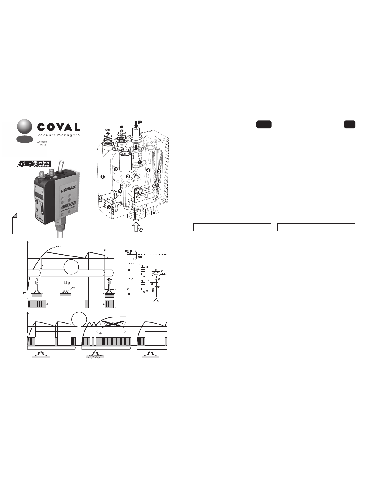
A- The "Air Saving Control" automatic cycle
Example with a LEMAX--X--Smodule; On this module, the solenoid
valve ➋is normally closed (NC).
The Adiagram presents the 3 steps of the cycle:
1- Product gripping
Pressure regulator* ➊supplies 3.5 bar to the "vacuum" solenoid
valve ➋. Vacuum signal vstarts the cycle by piloting valve ➋that
feeds venturi ➌. The generated vacuum grips the product. At 65%
vac., vacuum sensor ➏generates the "product gripped" rsignal
that authorizes next step.
2- Operations on vacuum gripped product
The operations on the product (transfer, machining…) will start.
When vacuum reaches threshold L2 (75%), the pressure supply
to the venturi is automatically stopped by solenoid valve ➋no
more consumption. The product remains gripped by vacuum Vthat
is preserved, due to the closing of poppet ➎. Micro-leaks may lead
to the decrease in vacuum level. Each time it goes below L2-h2
(65%), the vacuum level is regenerated to L2 (75%) thanks to a
brief pressure supply to the venturi.
3- Product release
At the end of operations, release is ordered. "Blow-off" solenoid
valve ➑, piloted by blow-off signal b, generates an air jet that
closes isolation valve ➓and, through flow regulator ➒, blows off
the product for a quick release.
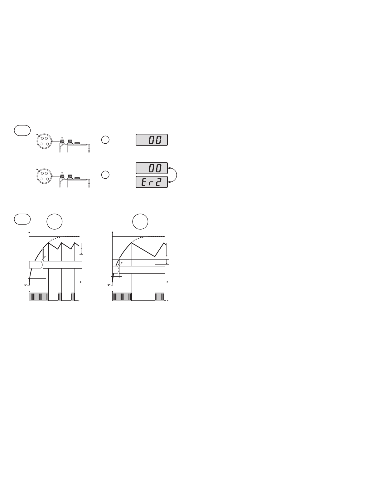
B- "Air Saving Control" cycle self-adaptation
The Bdiagram shows how the module adapts the cycle to fit to the
production realities: leaks due to products, to vacuum pads…
- Here, cycle 1 deals with an air tight product under the influence of
"ASC", resulting in optimum energy savings.
- At cycle 2 however, the porous product generates leaks that
provoke repeated intermittent vacuum regeneration. The anomaly is
automatically detected, and the cycle goes on but without "ASC. A
"ASC missing" signal is then emitted and displayed, and production
goes on.
- Cycle 3 illustrates the automatic return to the "ASC" cycle as
soon as leaks are eliminated: air tight products, vacuum circuit
maintenance…
The LEMAX module thus provides the maximum energy saving,
without any limitations to the performance and functioning of the
overall production system.
integrated compact
vacuum pumps
Operating instruction
ENG
LEMAX
modules
This document is intended for users of LEMAX vacuum pumps in the
following versions:
- LEMAX90X--S - LEMAX90X--SC14
- LEMAX90X--V - LEMAX90X--W
* The pressure regulator ➊is included on standalone modules only.
V4.0.1 software
h2=10%
I - BETRIEB
Die LEMAX-Vakuumpumpen funktionieren in „ASC“: Air Saving Control.
Sobald das Vakuum hergestellt ist, verbraucht das Modul nicht weiter, um
das Vakuum aufrecht zu erhalten. Die derart erzielte Energieeinsparung
ist ein wesentlicher Fortschritt. Und so wird sie erzielt.
A- Der automatische Air Saving Control-Zyklus
Beispiel mit einem Modul LEMAX--X--S; bei diesem Modul ist das
Elektromagnetventil ➋normal geschlossen (NC).
Das Nomogramm Azeigt die 3 Schritte des Zyklus.
1- Werkstückaufnahme
Der Druckregler* ➊versorgt das „Vakuum“-Magnetventil ➋. Das
Signal vzum Steuern des Vakuums startet den Zyklus unter Steuern
von ➋, das das Venturi ➌ versorgt. Das dabei erzeugte Vakuum erfasst
das Werkstück. Bei 65 % Vakuum erzeugt der Vakuumschalter ➏das
Signal r„Werkstückaufnahme“, das den nächsten Schritt erlaubt.
2- Vorgänge an den vom Vakuum gehaltenen Werkstücken
Die Vorgänge an dem Werkstück (Transfer, Bearbeitung,…) finden
jetzt statt. Wenn das Vakuum den Schaltwert L2 (75%) erreicht, wird
die Versorgung der Venturidüse vom Magnetventil ➋unterbrochen.
Der Druckluftverbrauch sinkt auf null. Das Werkstück wird weiterhin,
durch das Schließen der Klappe ➎, vom Vakuum Vgehalten. Das
Vakuumniveau wird hierdurch aufrechterhalten. Mikroleckagen
können das Niveau des Vakuums langsam absinken lassen.
Immer, wenn das Vakuum auf L2-h2 (65%) sinkt, wird eine kurze
Vakuumerzeugung ausgelöst, um auf L2 (75 %) zurückzukehren.
3- Werkstückablegen
Am Ende des Vorgangs wird das Ablegen angesteuert. Das
Magnetventil „Abblasen“ ➑, das vom Signal bder Abblassteuerung
gesteuert wird, erzeugt einen Luftstrahl, der das Absperrventil ➓
schließt und bläst das Werkstück für ein schnelles Ablegen über die
Durchflusseinstellung ➒.
B- Automatische Anpassung des Air Saving Control-Zyklus
Das Nomogramm Bzeigt, wie das Modul den Zyklus in Abhängigkeit
von den Produktionsgegebenheiten anpasst: Lecks auf Grund der
Werkstücke, der Saugnäpfe,…
- Hier verarbeitet der Zyklus 1 ein dichtes Werkstück und läuft in
„ASC“ mit optimaler Energieeinsparung ab.
- Im Zyklus 2 hingegen, kommt ein poröses Werkstück an, dessen Lecks
aufeinander folgende „schlagende“ Verbesserungen des Vakuums
auslösen. Diese Anomalie wird automatisch erkannt und der Betrieb
wird fortgesetzt, allerdings ohne „ASC“. Ein Signal „Ohne ASC“ wird
ausgegeben und angezeigt, die Produktion wird fortgesetzt.
- Der 3. Zyklus veranschaulicht die automatische Rückkehr zum
„ASC“-Betrieb, sobald die Lecks eliminiert sind: das Werkstück ist
dicht, der Vakuumkreislauf wird aufrecht erhalten, …
Das LEMAX-Modul stellt daher die maximale Energieeinsparung sicher,
ohne irgendwelche Zwänge aufzuerlegen und ohne den Betrieb jemals
zu unterbrechen.
Diese Dokument richtet sich an Nutzer der LEMAX Vakuumpumpen,
folgender Versionen:
- LEMAX90X--S - LEMAX90X--SC14
- LEMAX90X--V - LEMAX90X--W
* Der Druckregler ➊ist nur für die autonomen Module verfügbar.
V4.0.1 Software
Kompakte integrierte
Vakuumpumpen
Bedienungsanleitung
D
LEMAX
modules
1

1LEMAX90X--S2LEMAX90X--V
P=4.5/7 bar
3.5 bar
NC
NF
P=4.5/7 bar
3.5 bar
NO
3LEMAX90X--W
P=4.5/7 bar
3.5 bar
NO
II
1
LEMFIXA
LEMFIXB
LEMFIXB
2
DIN
35
3
Ø 4
LEMFIXA
Ø 4
64
13.5
Ø 4.2
32.510
64.5
18.5
G1/4"-F
75
85
25
15
76
29.9
6.7 64.5
71.2
35
DIN
LEMFIXA
LEMFIXB
III
- 2 -
II - AUSWAHL DES RICHTIGEN MODULS
Um jede Art von Bedarf zu decken, weist die Produktreihe von LEMAX
autonome und Inselmodule auf, die jeweils eine Steuerung des Vakuums
mit Normalerweise Geschlossenem (NF) und Normalerweise Offenem
(NO) Magnetventil haben. Um Ihr Modul anhand der vorliegenden
Anweisungen effizient zu nutzen, müssen Sie in der Produktreihe anhand
seiner Bezeichnung das passende Modul ausfindig machen.
A- AUTONOME MODULE
1- LEMAX90X--S und LEMAX90X--SC14
Bei diesem Modul ist das Magnetventil ➋ Normalerweise Geschlossen
(NC). Bei Stromausfall wird kein Vakuum mehr erzeugt.
2- LEMAX90X--V
Bei diesem Modul ist das Magnetventil ➋ Normalerweise offen
(NO). Bei Stromausfall wird das Vakuum weiterhin erzeugt, um das
Werkstück zu halten: Sicherheitshalten.
Diese Module werden von ein und demselben Signal vgesteuert,
das von der Steuerung der Anlage kommt. Für das NO-Modell erfolgt
die Umkehrung des Signals in v
–
produktintern.
3- LEMAX90X--W
Bei diesem Modul ist das Magnetventil ➋ normalerweise offen NO. Bei
Stromausfall wird das Vakuum weiterhin erzeugt: Sicherheitsfunktion.
In dieser Version NO, steuert das Signal v"Vakuum aus"
B- INSELMODULE
Alle oben beschriebenen autonomen Module gibt es auch in einer
Inselversion: LEMAX90X---B.
Wenn alle Inselmodule identisch sind, wird die Insel zusammengebaut
geliefert: Gegenüberstehend das Modul LEMAX90X---B3, eine Insel,
die aus 3 identischen Modulen besteht.
Gehören die Module zu unterschiedlichen Typen, werden sie einzeln
geliefert, jedes mit einem Satz von Endteilen, die für ihr Zusammenbauen
vor Ort in Abhängigkeit von den Erfordernissen der Anlage nötig sind.
Jedes Inselmodul wird von der gemeinsamen Druckversorgung, die die
ganze Insel durchquert, versorgt (siehe Skizze).
III - ANORDNUNG
A- AUTONOME MODULE
Auswahl aus 3 Anordnungstypen:
1- Befestigung von der Seite
2 durchgehende Schrauben Ø 4 mm mit breiten Unterlegscheiben
unter den Köpfen.
2- Befestigung von vorn
- Das Modul mit den 4 mitgelieferten Schrauben ➊auf die LEMFIXA
Platte schrauben.
- Befestigung mit 2 Schrauben Ø 4 mm.
3- Befestigung auf DIN-Schiene
- Das Modul mit den 4 mitgelieferten Schrauben ➊auf die LEMFIXB
Platte schrauben.
- Das Modul mit dem Clip der Platte LEMFIXB auf die Schiene zu 35
mm clipsen.
Wichtig
Für kurze Reaktionszeiten und einen minimalen Verbrauch, ordnet
man das Modul möglichst nahe an den Saugnäpfen an.
III - MOUNTING
A- STAND-ALONE MODULES
Mounting options: 3 types
1- Mounting from side
2 protruding screws Ø 4mm with large washers.
2- Mounting from front
- install the fixing plate LEMFIXA with 4 screws ➊ furnished with
product.
- Mount with 2 screws Ø 4mm .
3- Mounting over a DIN rail
- Fix the plate LEMFIXB on the module with the 4 screws ➊furnished
with the product.
- Clip on the module over the 35 mm DIN rail, with the plate LEMFIXB clip.
Important
For short response times and minimum consumption install the
module close to suction pads.
II - IDENTIFYING YOUR MODULE
In order to answer ta all needs, the LEMAX range includes stand-alone
and island modules, each of them with a vacuum solenoid valve either
NC or NO. For an efficient installation of your LEM module with the
current operating instructions, it is necessary to identify your module
with the help of its specific reference.
A- STAND-ALONE MODULES
1- LEMAX90X--S and LEMAX90X--SC14
On this module, solenoid valve ➋ is Normally Closed (NC). In case
of electrical cut-off, the vacuum generation stops.
2- LEMAX90X--V
On this module, solenoid valve ➋ is Normally Open (NO). In case
of electrical cut-off, the vacuum generation goes on to hold the
product: positive security.
These modules are controlled by the same v signal provided by
the installation control. In fact, for the NO version, the inversion of
the signal to v
–
is internal to the product.
3- LEMAX90X--W
On this module, solenoid valve ➋ is normally open (NO). In the
event of an electrical failure, vacuum continues to be generated,
thus holding the part: product safety.
In this NO version, the signal vcontrols the vacuum shutdown.
B- ISLAND MODULES
All stand-alone modules described above also have a version to be
island assembled : LEMAX90X---B.
If all modules in an island are identical, this island is supplied all
assembled : see example LEMAX90X---B3,3 identical modules
island.
If modules are different, they are supplied separately, together with the
island end set to complete the assembling on site in accordance to the
requirements of the application.
In the island, each module is fed by common pressure covering the
whole island (see figure).
The switching type of the inputs / outputs can be set to PNP (by
default) or NPN (see IX-4).
Der Schaltmodus der Ein- / Ausgänge ist in PNP (Standard) oder
NPN (siehe IX-4) konfigurierbar.

Ø4.2
Ø4.2
Ø4.2
Ø4.2
25 2020
LEMAX90X---B3
Torx T8
25 x n LEMAX + 20
25 x n LEMAX + 40
2
3 4
20 25 25
25 x n LEMAX + 40
25
1
64.5
25
10
24.515
37
0.5
64.5
26
G1/4"-F
64.5
7.5 2235
65.5
DIN
71
clip
33.5
10
G1/4"-F
B
L
A
A
A
B
P4.5/7 bar Ø6
1.0 mm
1.2 mm
1.4 mm
2 3 4 5 6 7 8 9
Simultaneously active module number
Anzahl der gleichzeitig aktiven Module
nozzle ID
Düse ID
G1/8"-F
P= 4 bar
BB
d
D
G1/4"-F
IV - TUBE CONNECTIONS
A- CONNECTION FOR PRESSURE SUPPLY
- 5µ filtered, non-lubricated air relevant to standard ISO 8573-1:2010
[4:5:4].
1- Stand-alone modules
- Push fitting for 6 mm OD tube (A).
- Network pressure P= 4.5 to 7 bar.
2- Islands
- Side connection on threaded port G1/8"-F (A), on one or both island
ends, depending upon simultaneously active number and size of
units: nozzle ID 1.0 mm, 1.2 mm or 1.4 mm.
Follow table recommendations.
- Pressure preferably regulated to 4 bar for energy savings and noise free
performance (island stacked modules have no integrated regulator).
B- VACUUM CIRCUIT CONNECTION
For an optimum performance with "Air saving control" it's a must to
maintain the airtightness of the vacuum network at all times. If there is
movement of the vacuum tube with respect to the module, a compresssion
fitting (illustration) is recommended to assure an air-tight connection.
see COVAL catalogue, fittings choice for tubes dxD= 4x6 mm, 6x8
mm, 8x10 mm.
Important: for short response times and minimum consumption it
is advised to reduce the volume to be evacuated.
While doing this, the module is installed closed to the suction pads
and the length L of the tube connecting the suction pads is as short
as possible.
Note : module's protection
- Vacuum entry sieve
A 200 µ sieve, integrated in port B, protects the module by stopping
any abrasive particle (sand…).
- Possible additional filter on vacuum circuit
In the rare cases of thin dust in wet environment, an adequate filter
will prevent any clogging:
see COVAL catalog, "vacuum circuit filters".
IV - ANSCHLÜSSE
A- ANSCHLUSS DER DRUCKVERSORGUNG
- Gefilterte, nicht geölte Luft, 5 µm gemäß Norm ISO 8573-1:2010
[4:5:4].
1- Autonome Module
- Schnellkupplung für Schlauch Ø 6 mm (A).
- Druck des Netzes: P= 4.5 bis 7 bar.
2- Inseln
- Anschluss an Gewindeöffnung G1/8"-F (A), auf einer oder auf beiden
Seiten der Insel, in Abhängigkeit von der Anzahl der gleichzeitig aktiven
Module und von ihrer Leistung : Düsen Ø 1 mm, 1,2 mm oder 1,4 mm.
Die Anweisungen der links stehenden Tabelle einhalten.
- Druck vorzugsweise zum Energiesparen und für ruhigen Betrieb auf
4 bar entspannt (die vereinten Module haben keinen integrierten
Druckminderer).
B- ANSCHLUSS AN VAKUUMKREISLAUF
Für einen zufriedenstellenden „Air Saving Control“, muss der Vakuumkreis-
lauf dauerhaft dicht sein. Wenn sich der Schlauch in Bezug zum Modul
bewegt, wird ein Anschluss mit geschraubter Kappe (Abbildung) empfohlen.
Siehe COVAL-Katalog, Auswahl der Schlauchanschlüsse dxD =
4x6 mm, 6x8 mm und 8x10 mm.
Wichtig: für kurze Reaktionszeiten und einen minimalen Verbrauch,
ordnet man das Modul möglichst nahe an den Saugnäpfen an. Dazu
und weil das Modul möglichst nahe an den Saugnäpfen angeordnet
wird, muss dafür gesorgt werden, dass die Länge L des Schlauches,
das sie mit dem Modul verbindet, möglichst kurz gehalten wird.
Hinweis: Schutz des Moduls
- Siebfilter am Eingang des Vakuums
In die Öffnung B ist ein Siebfilter zu 200 µ eingebaut, um das Modul
zu schützen und scheuernde Partikel aufzufangen (Sand usw.).
- Eventuell zusätzlicher Filter auf dem Vakuumkreislauf
In seltenen Fällen, wenn feiner Staub in feuchter Umgebung vorliegt,
vermeidet ein entsprechender Filter ein internes Verstopfen:
siehe Katalog COVAL „Filter für Vakuumkreisläufe“.
IV
- 3 -
B- INSELMODULE
1- Zusammengebaute Inseln
Wenn es sich um Module des gleichen Typs handelt, wird die
Insel zusammengebaut geliefert, zum Einbauen, Verbinden und
Anschließen bereit.
2- Zusammenbauen einer Insel
Die Module sind unterschiedlichen Typs und werden in Abhängigkeit
von den Erfordernissen der Anlage in Inseln angeordnet. Das
Zusammenbauen erfolgt durch einfaches Schrauben eines Moduls
auf das andere, mit einem Schraubendreher Torx T8 (Abbildung).
3- Befestigen einer Insel von vorn
mit 2 durchgehenden Schrauben Ø 4 mm.
4- Befestigung einer Insel auf DIN-Schiene
Der Befestigungsbausatz LEMFIXC besteht aus 2 Schrauben und 2
Clips, um jedes der Enden der Insel auszustatten. Die Insel wird auf
das DIN-Profil geclipst.
Anmerkung: Alle Maßangaben in mm.
B- ISLAND MODULES
1- Pre-assembled island
With all identical modules, the island is supplied all assembled,
ready for fixation and connections.
2- Island assembly
When different, the modules may be positionned into the island
according to the installation needs.
Assembly is easily made by screwing each module on the other,
using a T8 Torx screw driver (illustration).
3- Island mounting from front
2 protruding screws Ø 4mm.
4- Island mounting over a DIN rail
Fixing set LEMFIXC provides 2 screws and 2 clips to equip each
island end. The island may then be clipped over the DIN rail.
Note: All dimensions are in mm.

OUT IN
(LEMAX90X--S / LEMAX90X--V / LEMAX90X--W)
B1 A1
2
1
4
3
2
1
4
3
OUT
24 V
5 V
0 V0 V
IN
CDM8
OUT IN
CCM8
B2
B3
A2
(LEMAX90X--S)
2
1
4
3
2
1
4
3
24 V
1➝ 5 V
0 V
0 V
V
VI
PNP
NPN
V - ELECTRICAL CONNECTIONS
The LEMAX vacuum pump must be used with power supply units
that provide a Protective Extra Low Voltage (PELV) and with an
isolation of the supply voltage according to EN60204.
The electrical connections to be made depend of the module use,
which will also correspond to a specific configuration illustrated in
chapter IX.
A- IN connections
PIN 3 (blue wire) ➞0V permanent.
PIN 2 (white wire):
- LEMAX90X version --S/ LEMAX90X version --V ➞vacuum
command v .
- Version LEMAX90X--W ➞command v = vacuum stop.
A1- Connection for blow-off controlled by specific signal
PIN 4 (black wire) ➞blow-off command b.
A2- Connection for automatic-timed blow-off (see VIII-3)
PIN 4 (black wire) ➞no connection.
note : automatic-timed blow-off only on LEMAX90X--S.
B- OUT connections
Permanent supplies:
PIN 3 (blue wire) ➞ 0V PIN 1 (brown wire) ➞ 24V
PIN 4 (black wire) ➞switching output r
B1- Connection for "ASC missing" signal (see VIII-2)
PIN 2 (white wire) ➞output “ASC missing” signal + 5V DC output NO.
B2- Connection for "vacuum level" signal (see VIII-2)
PIN 2 (white wire) ➞output analogic signal 1 to 5V DC.
B3-Connection version LEMAX90X--SC14
PIN 2 (white wire) ➞vacuum control v
VI - DIALOGUE PANEL
A- Dialogue
Visual indicator v signal vacuum command (green).
Visual indicator bsignal blow-off command (orange).
Vacuum manual override.
Blow-off manual override.
Operation indicator "vacuum" (green).
Operation indicator "blow-off"(orange).
3 digit digital display.
Visual indicator "gripped product" (green).
Keyboard: configurations and settings.
Blow-off flow regulator.
B- Configuration
3 digit digital display :
- configuration and diagnostics interface
- production follow-up.
Keyboard :
- M: mode selection.a
- +& −: value selection.
V - ELEKTROANSCHLÜSSE
Die LEMAX-Vakuumpumpe erfordert die Verwendung von
Schutzkleinspannung (= PELV - Protective Extra Low Voltage)
und eine sichere Trennung von der Versorgungsspannung nach
EN60204.
Die herzustellenden elektrischen Anschlüsse hängen vom
Gebrauch des Moduls ab, von dem auch ein Parametrieren, in
Kapitel IX angegeben, abhängt.
A- Anschlüsse IN
PIN 3 (blauer Leiter) ➞0V permanent.
PIN 2 (weißer Leiter):
- Version LEMAX90X--S/ LEMAX90X--V ➞Vakuumsteuerung v .
- Version LEMAX90X--W ➞command v = Vakuumstopp.
A1- Anschluss für durch spezifisches Signal gesteuertes Abblasen
PIN 4 (schwarzer Leiter) ➞Abblassteuerung b.
A2-Anschluss für Self-Timed Abblasen (siehe VIII-3)
PIN 4 (schwarzer Leiter) ➞kein Anschluss.
Hinweis: Das Self-Timed Abblasen ist nur auf LEMAX90X--S
verfügbar.
B- Anschlüsse OUT
Ständige Versorgungen:
PIN 3 (blauer Leiter) ➞0V PIN 1 (brauner Leiter) ➞24V
PIN 4 (schwarzer Leiter) ➞Signalausgang r
B1- Anschluss für das Signal „ohne ASC“ (siehe VIII-2)
PIN 2 (weißer Leiter) ➞Signalausgang „ohne ASC“ + 5 V DC NO.
B2- Anschluss für das Signal „Vakuumlevel“ (siehe VIII-2)
PIN 2 (weißer Leiter) ➞Ausgang für Analogsignal 1 bis 5 V DC.
B3- Anschlussversion LEMAX90X--SC14
PIN 2 (weißer Draht) ➞Vakuumkontrolle v
VI - ANZEIGE UND BEDIENFELD
A- Zustand und Bedienfeld
Anzeigelampe Steuersignal des Vakuums v (grün).
Anzeigelampe Steuersignal des Abblasens b(orange).
Manuelles Steuern des Vakuums.
Manuelles Steuern des Abblasens.
Statusanzeige „Vakuums“ (grün).
Statusanzeige „Abblasen“ (orange).
Anzeige 3-Stellig 7 Ziffern.
Anzeige „Objekt angesaugt“ (grün).
Tastatur: Parametrierung und Einstellung.
Einstellung des Abblas-Volumenstroms.
B- Konfiguration
Anzeige 3-Stellig 7 Ziffern :
- Bedienfeld für Parametrierung und Einstellung.
- Betriebsüberwachung.
Bedientastatur :
- M: Auswahl der Betriebsart.
- +& −: Auswahl des Werts.
BN: brown
BK: black
BU: blue
WH: white
The switching type of the inputs / outputs can be set to PNP ( by
default) or NPN (see IX-4).
Der Schaltmodus der Ein- / Ausgänge ist in PNP (Standard) oder
NPN (siehe IX-4) konfigurierbar.
+ 24V DC
v
b
0V DC
LEMAX PNP IN
2 WH
4 BK
3 BU
LEMAX NPN IN
v
b
0V DC
2 WH
4 BK
3 BU
RL
1 BN + 24V DC
5 V DC / 1➞5V
r
0V DC
LEMAX PNP OUT
2 WH
4 BK
3 BU
RL
1 BN + 24V DC
r
5 V DC / 1➞5V
0V DC
LEMAX NPN OUT
4 BR
2 WH
3 BU
2
1
4
3
24 V 0 V
- 4 -

Factory Setting
COUNTER CMD
FW Version
AUTO BLOWOFF
L1/h1
L2/h2
UNIT
DIAG ECO
VII - FUNCTIONS SYNOPTIC
Keypad locking/unlocking: UnL/ Loc
(see IX-B)
Electronic manual controls
(see chap. VIII)
Back to “factory” settings: FAC (see XII-4)
Cycle number display: ct1/ct2/ct3
(see X-A)
Firmware version: Fir (see X-B)
Threshold 1 setting: L-1/ h-1 (see XII-1)
Threshold 2 setting: L-2/ h-2 (see XII-2)
Choice of vacuum level display unit: uni
(see IX-1)
Pct (%), -ba (mbar), -iH (inHg).
Activation of "anti-pulsation" DIAG ECO: Eco
(see XII-3) or auxiliary output setting AnA/
dEF(see IX-2)
Activation and setting of timed
automatic blow-off: Abl (see IX-3)
Input/Output switching type. Can be set to
PnP (by default) or nPn (see IX-4).
Factory Setting
COUNTER CMD
FW Version
AUTO BLOWOFF
L1/h1
L2/h2
UNIT
DIAG ECO
VII - MENÜ-ÜBERSICHT
Tastaturverriegelung/-entriegelung:
UnL/ Loc (siehe IX-B)
Manuelle elektronische Steuerung
(siehe VIII)
Rücksetzung auf werkseitige Einstellung:
FAC (siehe XII-4)
Anzahl der Zyklenzahl: ct1/ct2/ct3
(siehe X-A)
Firmware-Version: Fir (siehe X-B)
Einstellung des Grenzwerts 1: L-1/ h-1
(siehe XII-1)
Einstellung des Grenzwerts 2: L-2/ h-2
(siehe XII-2)
Auswahl der Anzeigeeinheit für das Vakuum-
niveau: uni (siehe IX-1)
Pct (%), -ba (mbar), -iH (inHg).
Aktivierung der „Anti-Pulsierung“ DIAG ECO:
Eco (siehe XII-3) oder Parametrierung des
Hilfsausgangs AnA/ dEF(siehe IX-2)
Aktivierung und Parametrierung des automa-
tischen zeitverzögerten Abblasens: Abl
(siehe IX-3)
Der Schaltmodus der Ein- / Ausgänge ist
in PnP (Standard) oder nPn (siehe IX-4)
konfigurierbar.
VII
2s3s CTR
Vacuum
CMD
L1
h1
CTR
Vacuum
Pilot
FW Version
IHM
HMI
&
Factory Setting
&
3s 3s
2s
2s
CTR
Blow
Pilot
2s
L2
h2
%
mbar
inHg
UNIT
ON OFF
DIAG ECO
PNP NPN
TYPE
0.1s
OFF ON
AUTO BLOWOFF
3s Electronic
manual override
Vacuum
Blow-off
888.888.888 888.888.888 888.888.888
8.8
3
VIII
1
3s
2
4
5
10s
VIII - ELECTRONIC MANUAL CONTROLS
The LEMAX vacuum pumps have electronic manual control of the
vacuum and blow-off solenoid valves.
This manual control is only available after the keypad is unlocked
(chap. IX-B).
1- Pressing once on −for 3 sec. switches into manual command
mode.
2- mAn appears on the display.
3- Pressing once on +activates the vacuum solenoid valve (“vacu-
um” status indicator lights up green on the dialogue panel)
or press once on −activates the blow-off solenoid valve (“blow-off”
status indicator lights up orange on the dialogue panel).
4- Wait 10 sec. or press Mallows you to leave this mode.
5- Return to 00 vacuum level display.
VIII - MANUELLE ELEKTRONISCHE
STEUERUNG
Die Vakuumpumpen LEMAX verfügen über eine manuelle
elektronische Steuerung des Vakuums und Abblasens durch ein
Magnetventil.
Für diese manuelle Steuerung muss zunächst einmal die Tastatur
entriegelt werden (Kap. IX-B).
1- 1 Druck auf −während 3 s zum Umschalten in die manuelle
Steuerung.
2- Auf der Anzeige erscheint mAn.
3- 1 Druck auf +aktiviert das Magnetventil zur Steuerung des
Vakuums (Statusanzeige „Vakuum“ im Dialogfeld leuchtet grün)
oder 1 Druck auf −aktiviert das Magnetventil zur Steuerung des
Abblasens (Statusanzeige „Abblasen“ im Dialogfeld leuchtet
orange).
4- 10 s warten oder auf Mdrücken, um den Modus zu beenden.
5- Für das Vakuumniveau wird erneut 00 angezeigt.
Electronic
manual override
Electronic
manual override
TYPE TYPE
- 5 -

2
1 2
1
2s
IX - CONFIGURATIONS
Configurations are made with display and keyboard .
3 functions may be configured:
Unit (IX-1).
Auxiliary output (IX-2).
Blow-off (IX-3).
The switching type of the inputs/outputs can be set to PNP/NPN
(IX 4).
A- Power ON
Switching on the power supply leads to the following actions:
1- Displaying 8.8.8. for 0.5 s.
2- Fixed display 00 (vacuum level).
Any power loss, followed by a re-connection entails these 2 actions,
and the keyboard remains locked, ie non-operative.
B- Keyboard unlocking
1- A simultaneous actuation of Mand −unlocks the keyboard (then,
the same action will block it).
2- Each successive pressing shows, respectively, UnL, Locthen
00.
IX-1- Unit
The vacuum level display unit can be either : %, mbar or inHg.
1- Pressing the Mkey 3 times gives access to the choice of vacuum
level display unit.
2- The message uni is displayed for 2s and confirms this mode.
3- Default unit (factory setting) is displayed: Pct.
4- Pressing +enables you to go from Pct to -bA then -iH in
turn. The unit selected remains displayed (e.g.: mbar).
5- The selection is automatically memorized, then automatic return
to the 00 vacuum level display after 5 sec. (or press M).
IX - PARAMETRIERUNG
Die Parametrierung verwendet die Anzeige und das Bedienfeld .
3 Funktionen können parametriert werden:
Einheit (IX-1).
Hilfsausgang (IX-2).
Abblasen (IX-3).
Schaltmodus der Ein- / Ausgänge in PNP / NPN (IX-4) konfigurierbar.
A- Einschalten
Das Anschließen an die Stromversorgung bewirkt:
1- Anzeige 8.8.8. für 0,5 Sek.
2- Stationäre Anzeige 00 (Vakuumniveau).
Jedes Wiedereinschalten, das auf eine Unterbrechung der Stromver-
sorgung folgt, bewirkt diese 2 Vorgänge und die Tastatur bleibt
„blockiert“, das heißt gesperrt.
B- Entriegeln der Tastatur
1- Gleichzeitig auf Mund −drücken, um die Tastatur zu entriegeln
(ein erneutes Betätigen dieser Tasten sperrt sie wieder).
2- Bei jeden nachfolgenden Druck wird UnL, Loc dann 00
angezeigt.
IX-1- Anzeigeeinheiten
Für die Anzeige des Vakuumlevel, kann zwischen %, mbar oder Hg
ausgewählt werden.
1- 3 Betätigungen der Taste Maktivieren den Auswahlmodus für die
Anzeigeeinheiten des Vakuumlevel
2- Die Meldung uni erscheint für 2 Sek. als Bestätigung diese
Betriebsart.
3- Die werkseitig eingestellte Standardeinheit erscheint: Pct.
4- Mit mehrmaligem Drücken auf +wechselt die Anzeige von Pct auf
-iH und dann auf Hg. Die ausgewählte Einheit bleibt angezeigt (z.
B.: mbar).
5- Der ausgewählte Wert wird automatisch gespeichert. Die Rückkehr
zur Anzeige des Vakuumlevel 00 erfolgt automatisch nach 5s (oder
1 Druck auf M).
2 3
1x3
4
5
5s
IX
IX-1
- 6 -

1x4
3
a
c
b
IX-2- Auxiliary output
(Not available on LEMAX90X--SC14 version).
The initial factory setting for PIN2 of the OUT connector (chap. V) is set
on the B2 option: analogic “vacuum level” signal 1 to 5 V DC.
This setting is therefore only to be changed when using B1 option:
“without ASC” signal + 5 V switching output.
1- Pressing Mkey four times gives access to the output (OUT, PIN2)
configuration.
2- The Eco message confirms the air ECOnomy diagnostic mode.
At the end of this message, on is automatically displayed.
3- Analogic output selection.
a/ Pressing Mopens the choice between ANAlogic signal and DEFault
ASC signal (“ASC missing”).
b/ Pressing +toggles AnA or dEf alternately.
c/ Automatic return to 00.
IX-2- Zusätzlicher Ausgang
(Nicht verfügbar bei Ausführung LEMAX90X--SC14).
Der PIN 2 des Steckers OUT (Kap. V) wird werkseitig auf die Option
B2 eingestellt: analoges Signal "Vakuumlevel" 1 bis 5 V Gleichstrom.
Diese Parametrierung wird nur geändert in Zusammenhang mit die
Option B1: Signal "ohne ASC" + 5V TOR.
1- 4 Drücke auf die Taste Merlauben den Zugang zum Parametrieren
des Ausgangs (OUT, PIN2).
2- Die Meldung Eco bestätigt diesen Diagnose Modus. Am Ende
dieser Meldung wird automatisch on angezeigt.
3- Auswahl des analogen Ausgangs.
a/ Ein Druck auf Merlaubt den Zugang zur Auswahl zwischen
ANAlogem Signal oder dem Signal DEFaut ASC („ohne ASC“).
b/ Ein Druck auf +schaltet jeweils zwischen AnA und dEf um.
c/ Automatische Rückkehr zu 00.
2
IX-2
IX-3
1
x5
4
ac
b
2
IX-3- Abblasen
(Das automatisch verzögerte Abblasen ist bei den Ausführungen
LEMAX90X--Vund LEMAX90X--Wnicht verfügbar).
LEMAX90X--S: die werkseitige Einstellung des Abblasens ist die Option
A1 (Kap. V): „Gesteuertes Abblasen durch ein spezifisches Signal“.
Diese Parametrierung ändert der Benutzer nur, wenn er die Option A2
verwenden will. „Automatisch verzögertes Abblasen“ (Kap. V).
LEMAX90X--SC14: verfügt nur über ein automatisch verzögertes
Abblasen. Diese Einstellung ermöglicht, die Dauer des automatisch
verzögerten Abblasens zu ändern.
1- 5 Drücke auf die Taste M➞Abblasbetrieb.
2- Die Abrollmeldung AbL bestätigt diese Betriebsart. Sie stoppt auf
oFF. Um die externe Steuerung des Abblasens zu behalten, bleibt
man auf oFF. Die Speicherung erfolgt automatisch.
3- Wenn man das „automatische Abblasen“ wünscht, drückt man auf
+, um auf On überzugehen.
4- Auf On kann man die Dauer des automatischen Abblasens einstellen:
a/ Ein Druck auf M erlaubt das Zugreifen auf die Einstellung.
b/ Betätigungen von + erhöhen die Dauer, Drücke auf −verringern sie.
Die ausgewählte Dauer (0 bis 9.9 s) wird automatisch gespeichert.
c/ Nach einigen Sekunden tritt die Rückkehr zur Anzeige OO
(Vakuumlevel) ein.
3
IX-3- Blow-off
"Automatic timed blow-off" not available on LEMAX90X--Vand
LEMAX90X--W.
LEMAX90X--S: the initial factory setting of blow-off is set on the A1
option (chap. V): "blow-off controlled by specific signal".
This configuration is to be changed only for the A2 option: "automat-
ic-timed blow-off" (chap. V).
LEMAX90X--SC14: only has the automatic timed blow-off. This setting
allows you to modify the timing of the automatic timed blow-off.
1- Pressing M, 5 times➞blow-off mode.
2- The AbLmessage confirms that mode. Then, oFF is displayed.
To stay on "blow-off controlled by specific signal" stay on oFF.
Automatic memorization.
3- If "automatic-timed blow-off" is required, press the +to obtain On.
4- With On, blow-off timing is adjustable:
a/ Pressing on Mgives access to adjustment.
b/ Pressing on +increases timing while pressing on −decreases
blow-off time. Memorization is automatic (0 to 9.9 s).
c/ Wait for automatic return of O0, vacuum level.
- 7 -

X - CYCLES / VERSION DISPLAY
A- Cycle counter
1- Press the +key for 3s to get into this mode.
2- The display shows ct1 for 2s:
3- The counter (9 digits) scrolls per block of 3 digits (the point
indicates which block of the digits is displayed). Example: if ct1 =
006855456 0.06 for 2s then 85.5 for 2s then 456. for 2s.
The counter display loops until pressing the Mkey (transition to
ct2 counter).
4- The display shows ct2, then after 2s the counter value is scrolled
(the same for ct1).
NOTE :
ct1 is the number of vacuum external commands (impulses on the
signal input « Vacuum control » v ).
ct2 is the number of actual activations of the vacuum valve.
The difference between the two counters is used to determine the
trigger frequency of the ASC control system.
ct3 is the number of actual activations of the blow-off valve.
B- Firmware version
6- 1 pressing on M(after display of ct1 and ct2) allows to display
firmware version.
7- The display shows Fir.
8- The version appears after 2s, example4.0.1.
X - ANZEIGE ZYKLEN/VERSION
A- Zykluszäler
1- Druck für 3 Sek. auf die Taste +halten schaltet diesen Modus um.
2- Die Anzeige zeigt ct1 an und dann nach 2 Sek. :
3- Der Zähler (9-Stellig) läuft in 3 Ziffernblocks (der Punkt zeigt
an, welcher Zifferblock angezeigt wird). Beispiel: wenn ct1 =
006855456 0.06 für 2 Sek., dann 85.5 für 2 Sek. dann
456. für 2 Sek.
Die Anzeige des Zählers läuft weiter, bis zum Drücken auf die Taste
M(Übergang zum Zähler ct2)
4- Die Anzeige zeigt ct2 an, und dann nach 2 Sek. scrollt der Wert
des Zählers.
HINWEIS:
ct1 entspricht der Anzahl externer Vakuumbefehle (Impulse auf dem
Eingang des Signals "Vakuumsteuerung" v ).
ct2 entspricht der Anzahl tatsächlicher Aktivierungen des
Vakuumsventils.
Der Unterschied zwischen den 2 Zählern ermöglicht das Bestimmen
der Triggerfrequenz des ASC-Reguliersystems.
ct3 ist die Anzahl der tatsächlichen Aktivierungen des Abblasventils.
B- Firmware-Version
6- 1 Druck auf M(nach dem Anzeigen von ct1 oder ct2) ermöglicht
das Umschalten auf die Anzeige der Firmware-Version.
7- Das Display zeigt Fir an.
8- Die Version erscheint nach 2 s, Beispiel 4.0.1.
X
IX-4
IX-4- Input/Output switching type can be set to
PNP/NPN
The initial factory setting of Input/Output switching type is set on PNP
(chap. V): this configuration is to be changed only when NPN switching
type is required for Input/Output.
1- Pressing M, 6 times ➞Type mode.
2- The typmessage confirms that mode. Then, Pnp is displayed.
To stay on PNP, press Mto validate.
3- For NPN, press the +to obtain npn.
Memorization is automatic.
4- Wait for automatic return of O0, vacuum level.
IX-4- Der Schalttyp des Eingangs/Ausgangs kann
auf PNP/NPN eingestellt werden.
Die Werkseinstellung der Eingangs-/Ausgangsumschaltung ist auf PNP
eingestellt; (Kapitel V): diese Konfiguration darf nur geändert werden,
wenn eine NPN-Schaltung für den Ein- und Ausgang benötigt wird.
1- 6 Drücke auf die Taste M➞Modus-Typ.
2- Die typ Meldung bestätigt diesen Modus. Dann wird Pnp
angezeigt. Um PNP zu bestätigen, drücken Sie M.
3- Für NPN, drücken Sie +, um npn zu erhalten. Die Speicherung
erfolgt automatisch.
4- Warten auf automatische Rückkehr von O0, Vakuumniveau.
23
1
4
5
6 7 8
3s
ct3
1
x6
4
2
3
- 8 -

Vmax=85%
h2=10%
%V
L2=75%
L1=65%
0
0
c
t
t
A
1 2
B
h1=10%
2
1
4
3
OUT
OFF
2
1
4
3
OUT
ON
(5 V)
1 ASC
2 no ASC
XI - BETRIEBSÜBERWACHUNG
Der Betrieb mit ASC gewährleistet eine ausschlaggebende Einsparung:
In Abhängigkeit von den Anwendungen 60 bis 99 %. Der Betrieb
wird ohne ASC fortgesetzt, wenn die verarbeiteten Werkstücke porös
sind (Kap. I). Bei dichten Werkstücken wird der ASC-Betrieb solange
sichergestellt wie die Saugnäpfe und der Leckkreislauf kein Leck
aufweisen.
A- Betriebswarnungen ohne ASC
1- Beim ASC-Betrieb ist das Vakuumlevel auf der Anzeige 00
angezeigt (gemäß ausgewählten Einheit).
2- Beim Betrieb "ohne ASC" wechselt die Anzeige des Vakuumlevel
00mit der Anzeige des Fehlers Er2 ab.
Das Signal des PIN 2 des Steckers OUT kann auch als ergänzendes
Warnmittel genutzt werden (siehe Kap. V und VIII-2) (nicht verfügbar
bei LEMAX90X--SC14).
B- Aktionen für die Rückkehr zum ASC-Betrieb
Diese Warnung über den Betrieb ohne ASC fordert zu Wartungseingrif-
fen auf, die den Lecks abhelfen sollen: Wechseln des Saugnapfs,
Prüfen der Anschlüsse des Vakuumkreises, …
XI - OPERATIONS FOLLOW-UP
Operating with ASC ensures significant savings: 60 to 99%, depending
on application. Operations carry on without ASC when products are
porous (chap. I). With air tight products, ASC operating is assured, as
long as vacuum pads and vacuum circuit do not leak.
A- Operating without ASC alerts
1- In the ASC operation, the vacuum value is indicated on the display:
00 (according to the selected unit).
2- In the operation "without ASC", the display of vacuum value 00
alternates with the display of the Er2 error.
The OUT connector PIN 2 may also be used as a means to build
a complementary alert (see chap. V and VIII-2) (not available on
LEMAX90X--SC14).
B- Actions for the return to operations with ASC
This operating without ASC alert is a warning to perform maintenance
operations to eliminate the leaks: vacuum pads replacements, vacuum
circuit connections check…
XII - SPECIFIC SETTINGS
A- "Factory" setting reminder
This initial "factory" setting is convenient for most applications.
L1= 65%, vacuum threshold generating "gripped product" signal.
h1= 10%, L1 hysteresis, vacuum drop generating "gripped product"
signal disappearing.
L2= 75%, vacuum threshold emits vacuum generation cut-off.
h2= 10%, L2 hysteresis, vaccum drop signalling regeneration of vacuum.
The Adiagram recalls the operations controlled by this "factory" setting.
B- Custom settings
L1, L2, h1 and h2 are adjustable. This allows better performances in
some cases. Here are 2 examples:
1- Shorter gripping time
Vacuum pads are often oversized. This allows lowering of L1. Diagram
Bdemonstrates how gripping time thas been shortened.
2- Return to ASC operations
Diagram Bshows how, by increasing h2, vacuum regeneration that
may prevent ASC are avoided.
XII - SPEZIFISCHE EINSTELLUNGEN
A- Errinnerung auf die Werkseinstellungen
Die ursprüngliche Werkseinstellungen des Moduls ist für die meisten
Anwendungen geeignet.
L1= 65 %, Vakuumgrenzwert, der das Signal "Werkstückaufnahme"
erzeugt.
h1= 10 %, Hysterese von L1, Abfallunterschied, der das Verschwinden
des Signals "Werkstückaufnahme » bewirkt.
L2= 75 %, Vakuumgrenzwert, der das Abschalten der Vakuumerzeu-
gung auslöst.
h2= 10 %, Hysterese von L2, Abfallunterschied, der das
Wiederaufnehmen der Vakuumerzeugung bewirkt.
Das Diagramm Azeigt die mögliche Betriebe der Werkseinstellungen auf.
B- Verwenden einer spezifischen Einstellung
L1, L2, h1 und h2 können eingestellt werden, so dass man die
Leistung in bestimmten Fällen verbessern kann. 2 Beispiele:
1- Für eine kürzere Aufnahmezeit
Die Saugnäpfe sind oftmals zu groß eingesetzt, das ermöglicht den
Grenzwert für L1 zu senken. Das Diagramm Bzeigt die abgekürzte
Aufnahmezeit t an.
2- Rückkehr zum ASC-Betrieb
Das Nomogramm Bzeigt, wie man durch Erhöhen von h2 die
Nachbesserungen des Vakuums, die den ASC-Betrieb verhindern
können, beabstandet.
XI
XII
H2=25%
%V
L2=75%
L1=45%
0
0
c
t
t
1 2
H1=10%
- 9 -

1
5
4
2 3
6 7
5s
2s
8
XII-1- L1 and h1 settings
1- Pressing Monce brings us to L1 setting mode.
2- L-1 appears for 2s.
3- Display then specifies existing setting ( 65, for example).
4- By pressing on +or −, select the desired value:
- 0 to 99% if uni = Pct
- 0 to -29.9 inHg if uni = -iH
- 0 to -990 mbar if uni = -bA
The selected value is automatically memorized. After 5 sec, automatic
return to vacuum level display 00.
OR, if you wish to set h1, L1 hysteresis:
5- Press Monce (during this 5 s delay) to bring us to h1 setting.
6- h-1 appears for 2s.
7- Display then specifies existing setting (10, for example).
8- By pressing on +or −, select the desired value:
- 0 to 99% if uni = Pct
- 0 to -29.9 inHg if uni = -iH
- 0 to -990 mbar if uni = -bA
The selected value is automatically memorized. Then, return to vacuum
level display 00.
XII-1- Einstellung von L1 und h1
1- Einmal auf Mdrücken, um auf den Betrieb zum Einstellen des
Grenzwerts des Signals „Werkstückaufnahme“ L1 zu schalten.
2- L-1 erscheint für 2 Sek.
3- Auf dem Display wird dann der vorliegende Einstellwert angezeigt
(zum Beispiel 65).
4- Durch Drücken von +oder −den gewünschten Wert auswählen:
- 0 bis 99%, wenn uni = Pct
- 0 bis -29.9 inHg, wenn uni = -iH
- 0 bis -990 mbar, wenn uni = -bA
Der ausgewählte Wert wird automatisch gespeichert. Die Rückkehr zur
Anzeige des Vakuumlevel 00 erfolgt automatisch nach 5 Sekunden.
ODER wenn Sie die Hysterese h1 von L1 einstellen wollen:
5- 1 Mal auf M(innerhalb dieser 5 Sekunden), um auf den Betrieb
zum Einstellen von h1 umzuschalten.
6- h-1 erscheint für 2 Sek.
7- Auf dem Display wird dann der bestehende Einstellwert angezeigt
(zum Beispiel 10).
8- Durch Drücken von +oder −den gewünschten Wert auswählen:
- 0 bis 99%, wenn uni = Pct
- 0 bis -29.9 inHg, wenn uni = -iH
- 0 bis -990 mbar, wenn uni = -bA
Der ausgewählte Wert wird automatisch gespeichert, dann folgt die
Rückkehr zur Anzeige des Vakummlevel 00.
2s
2s
1
5
4
2 3
6 7
2s
8
5s
XII-2- L2 and h2 settings
1- Pressing Mtwice bring us to L2 setting mode.
2- L-2 appears for 2s.
3- Display then specifies existing setting ( 75, for example).
4- By pressing on +or −, select the desired value:
- 0 to 99% if uni = Pct
- 0 to -29.9 inHg if uni = -iH
- 0 to -990 mbar if uni = -bA
The selected value is automatically memorized. After 5 sec, automatic
return to vacuum level display 00.
OR, if you wish to set h2, L2 hysteresis:
5- Press on M(during this 5 s delay) to bring us to h2 setting.
6- h-2 appears for 2s.
7- Display then specifies existing setting (10, for example).
8- By pressing on +or −, select the desired value:
- 0 to 99% if uni = Pct
- 0 to -29.9 inHg if uni = -iH
- 0 to -990 mbar if uni = -bA
The selected value is automatically memorized. Then, return to vacuum
level display 00.
XII-2- Einstellung von L2 und h2
1- Zweimal auf Mdrücken, um auf den Betrieb zum Einstellen des
Grenzwerts „ASC“ L2 zu schalten.
2- L-2 erscheint für 2 s.
3- Auf dem Display wird dann der bestehende Einstellwert angezeigt
(zum Beispiel 75).
4- Durch Drücken von +oder −den gewünschten Wert auswählen:
- 0 bis 99%, wenn uni = Pct
- 0 bis -29.9 inHg, wenn uni = -iH
- 0 bis -990 mbar, wenn uni = -bA
Der ausgewählte Wert wird automatisch gespeichert. Die Rückkehr zur
Anzeige des Vakuumlevel 00 erfolgt automatisch nach 5 Sekunden.
ODER wenn Sie die Hysterese h2 von L2 einstellen wollen:
5- 1 Mal auf Mdrücken (innerhalb dieser 5 Sekunden), um auf den
Betrieb zum Einstellen von h2 umzuschalten.
6- h-2 erscheint für 2 s.
7- Auf dem Display wird dann der bestehende Einstellwert angezeigt
(zum Beispiel 10).
8- Durch Drücken von +oder −den gewünschten Wert auswählen:
- 0 bis 99%, wenn uni = Pct
- 0 bis -29.9 inHg, wenn uni = -iH
- 0 bis -990 mbar, wenn uni = -bA
Der ausgewählte Wert wird automatisch gespeichert, dann folgt die
Rückkehr zur Anzeige des Vakuumlevel 00.
XII-1
XII-2
- 10 -

XII-4
2s
XII-3- Deaktivieren des Diag Eco
Bei spezifischen Anwendungen kann der Diag Eco wie folgt deaktiviert
werden:
1- 4 Drücke auf die Taste Merlauben den Zugang zu dieser Einstellung.
2- Die Meldung Eco bestätigt die Betriebsart Air Saving ECOnomy
Diagnose - Werkseinstellung). Am Ende dieser Meldung wird
automatisch on angezeigt.
3- Durch Drücken auf +auf off schalten.
4- Ein Druck auf Moder automatische Rückkehr zur Anzeige des
Vakuumlevel 00nach 5 Sekunden.
12
x4
34
c
%V
0
L1=65%
L2=75%
Vmax=85%
t
without ASC
CYCLE 2
c
%V
0
L1=65%
L2=75%
Vmax=85%
t
CYCLE 2
5s
XII-3
XII-3- Disabling Diag Eco
For specific applications Diag Eco can be deactivated as follows:
1- Pressing M, 4 times provides access to this setting.
2- The Eco message confirms air saving ECOnomy diagnosis mode
(factory setting).
After 2 s, on is displayed automatically.
3- Switch to off by pressing +.
4- Press Mor automatic return to the vacuum level displaying 00after
5s.
Reminder of “factory” settings
L1 = 65% L2 = 75% h1 = 10% h2 = 10%
UNIT: % DIAG ECO = ON
AUXILIARY OUTPUT: ANA (not available on LEMAX90X--SC14)
AUTO BLOW-OFF :
- LEMAX90X--S, LEMAX90X--Vand LEMAX90X--W: OFF
- LEMAX90X--SC14 : ON
INPUT/OUTPUT SWITCHING TYPE: PNP
Werkseitige Einstellungen
L1 = 65% L2 = 75% h1 = 10% h2 = 10%
EINHEIT: % DIAG ECO = ON
HILFSAUSGANG: ANA (nicht verfügbar bei LEMAX90X--SC14)
AUTOMATISCHES ABBLASEN:
- LEMAX90X--S, LEMAX90X--Vund LEMAX90X--W: AUS
- LEMAX90X--SC14 : AN
EINGANGS- / AUSGANGS-SCHALTTYP: PNP
XII-4- Return to "factory" setting
A possible return to "factory" setting is obtained as follows.
1- Starting from the display position of the vacuum level 00, press
simultaneously the Mand +for 3 seconds (3s).
2- The FAC message appears for 3 seconds.
3- Within this interval of 3s, confirm the return to factory settings by
pressing the +(otherwise, there is automatic return to the vacuum
level display without resetting the parameters).
4- The FAC warning flashes for 3s to confirm the reset settings.
5- Automatic return to the vacuum level display 00.
XII-4- Rückkehr zu der Werkseinstellung
Eine eventuelle Rückkehr zu der Werksteinstellung wird wie folgt
ermöglicht:
1- Ausgehend von der Anzeige der Vakuumlevel 00, gleichzeitig M
und + für 3 Sek. lang drücken.
2- Die Meldung FAC erscheint 3 Sekunden lang.
3- In diesem Zeitintervall von 3 Sekunden, bestätigen Sie die Rückkehr
zu der Werkseinstellung beim drucken auf die +Taste (ansonsten
automatische Rückkehr zur Anzeige des Vakuumlevels ohne
Neuinitialisierung der Parameter).
4- Die Meldung FAC blinkt 3 Sekunden lang, um die Neuinitialisie-
rung zu bestätigen.
5- Automatische Rückkehr zur Anzeige der Vakuumlevel 00.
25
13s
3s
34
- 11 -

XIII
XIV- ERINNERUNG AUF DIE SPEZIFIKATIONEN
Allgemeine technische Daten
Versorgung: Druckluft gefiltert 5 µm, nicht geölt, nach IS0 8573-1
Klasse 3-4-3.
Betriebsdruck: 4.5 bis 7 bar.
Versorgungsdruck, dynamisch mind: - autonomen Module: 4.5 bar.
- Inselmodule : 4 bar.
Abblasen: Volumenstrom einstellbar:
- autonome Ausführung: P = 3,5 bar.
- Insel-Bauweise: P Luftdrucknetz.
Maximales Vakuum: 85 %.
Saugleistung: 29 bis 70 Nl/Min.
Luftverbrauch: 44 bis 90 Nl/mn im Betrieb "ohne ASC".
Schutzart Elektrizität: IP65.
Maximale Taktfrequenz: 4 Hz.
Lebensdauer: 30 Millionen Zyklen.
Gewicht: 130 g.
Betriebstemperatur: 10 bis 60 °C.
Material: PA 6-6 15 % glasfaserverstärkt (GF), Messing, Aluminium,
Nitrilkautschuk (NBR).
Integrierter Schalldämpfer
Schallpegel: etwa 68 dBA "ohne ASC". 0 dBA mit ASC.
Integrierter offener Schalldämpfer.
Elektrische Steuerungen
Steuerspannung: 24 V DC (regulierend ± 10 %) PNP oder NPN.
Stromaufnahme: 30 mA (0,7 W) Vakuum oder Abblasen.
Integrierte Elektronik
Stromversorgung 24 V; Stromaufnahme: <57mA.
Einstellbereich: 0 bis 99 % des Vakuums.
Messgenauigkeit: ±1,5 % des Einstellbereichs, temperaturkompensiert.
Hysterese: einstellbar von 0 % bis 100 %.
Anzeige: 3-Stellig 7 Ziffern.
Betriebsdaten
Ausgangssignal "Objekt angesaugt"
- 24 V DC, Schaltausgang NO, Ausschaltleistung: 125 mA PNP oder
NPN.
Regelbarer Nebenausgang, Zur Auswahl:
- entweder Signal "ohne ASC", +5 V Schaltausgang NO.
- oder Signal "Vakuumniveau", analog von 1 bis 5 V DC des
Messbereichs.
XIV - REMINDER FOR SPECIFICATIONS
General characteristics
C.A. supply 5µ filtered, non-lubricated air relevant to ISO 8573-1
class 3-4-3.
Optimal working pressure: 4.5 to 7 bar.
Mini dynamic pressure : - stand-alone module: 4,5 bar.
- island modules: 4 bar.
Blow-off: adjustable flow: - stand-alone modules: P = 3.5 bar.
- island modules: P supply.
Maximum vacuum: 85%.
Suction flow rate: From 29 to 70 Nl/min (1.02 to 2.47 SCFM).
Air consumption: From 44 to 90 Nl/min (1.55 to 3.18 SCFM), when
operating “without ASC”.
Electrical degree of protection: IP65.
Maximum frequency of utilization: 4 Hz.
Number of operations: 30 million cycles.
Weight: 130 g.
Working temperature: from 10 to 60°C (50 to 140°F).
Materials: PA 6-6 15%FG, brass, aluminium, NBR.
Integrated silencer
Sound level: about 68 dBA "without ASC", 0 dBA with ASC.
Clog free open silencer.
Electrical controls
Controls voltage: 24 V DC (adjustable ± 10 % ) PNP or NPN.
Current draw: 30 mA (0,7W) vacuum or blow-off.
Integrated electronics
Supply: 24 V DC ; current draw: <57mA.
Measure range: 0 to 99 % vacuum.
Measure precision: ±1.5 % of the range, temperature compensated.
Adjustable hysteresis: 0% to 100%.
Display: 3 digit digital display.
Service characteristics
"Gripped product" output signal
- 24V DC NO switching output, power: 125 mA PNP or NPN.
Configurable auxiliary output:
- either "without ASC" signal +5V DC NO switching output.
- or "vacuum level" signal, analogic O to 5V DC, along the 0 to 99%
vacuum measure range.
XIII - ALERTS and ERROR MESSAGES
Er1 : CURRENT FAULT ON S1
Current consumed on the S1 switching output exceeds the 125mA
limit.
Switch off, check the cause of overconsumption and/or reduce the
charging current to below 125mA. Switch on again.
Er2 : VACUUM NETWORK LEAK
Switchover to permanent suction due to a regulation default (more than
2 pulsations of the vacuum pilot in less than a second).
Check the airtightness of the vacuum network and/or the quality of
the product to be handled.
Er3 : PRODUCT HOLDING FAULT
Product lost during handling (active vacuum control)
Control the handling process.
XIII - WARNUNGEN UND
FEHLERMELDUNGEN
Er1 : UBERSPANNUNG AUF S1
Die Leistungsaufnahme am Ausgang TOR S1 liegt über 125mA.
Schalten Sie das Gerät aus, suchen Sie nach der Ursache für den
hohen Stromverbrauch und/oder reduzieren Sie den Laststrom auf
einen Wert unter 125mA. Schalten Sie das Gerät wieder ein.
Er2 : LECKAGE VAKUUMNETZ
Permanentes Absaugen infolge eines Regelungsfehlers (mehr als 2-mali-
ges Pulsieren (Vakuum ein/aus) der Vakuumsteuerung pro Sekunde).
Untersuchen Sie den Vakuumkreislauf auf Leckagen und
kontrollieren Sie die Qualität des Werkstücks.
Er3 : FEHLER BEIM GREIFEN DES TEILS
Werkstück hat sich während der Bearbeitung abgelöst (Vakuumsteue-
rung ist aktiviert) Kontrollieren Sie den Bearbeitungsprozess.
- 12 -

XV - LEISTUNGEN IN DER
AUFNAHMEPHASE
Das Senken von L1 verkürzt die Aufnahmezeit (Kap. XI). Die
nebenstehende Tabelle ist ein Leitfaden für die Suche nach der
optimalen Einstellung von L1: Sie zeigt die Entleerungszeiten eines
Vergleichsvolumens von 1 l bis zu einem gegebenen Schwellenwert
L1.
Man sieht, dass die Aufnahme kürzer ist:
- bei einem Mindestvolumen, das zu entleeren ist, im Vergleich zu 1 l
der Tabelle.
- bei einem Vakuumniveau L1, das gerade hoch genug eingestellt ist,
um ein sicheres Aufnehmen des Werkstücks zu ergeben.
www.coval.com
Die LEMAX-Bedienungsanleitung ist in verschiedenen Sprachen
auf unserer Website in PDF-Format verfügbar.
© COVAL - v5 - 09/2018 - Abbildungen nicht vertraglich.
Die Firma COVAL behält sich das Recht vor, ihre Produktreihe sowie die Merkmale ihrer
Produkte jederzeit unangekündigt zu ändern.
Emptying time for 1 liter volume
Entleerungszeit eines Volumens von 1 Liter
1.0 mm
1.2 mm
1.4 mm
LEMAX 90 X 10
12
14
55%
1.76 s
1.13 s
0.73 s
60%
2.04 s
1.31 s
0.85 s
65%
2.38 s
1.53 s
0.99 s
70%
2.80 s
1.80 s
1.16 s
75%
3.33 s
2.15 s
1.38 s
80%
4.09 s
2.64 s
1.70 s
Air consumption
(without ASC)
Luftverbrauch
(ohne ASC)
29 Nl/mn
1.02 SCFM
44 Nl/mn
1.55 SCFM
65 Nl/mn
2.30 SCFM
90 Nl/mn
3.18 SCFM
45 Nl/mn
1.59 SCFM
70 Nl/mn
2.47 SCFM
Air suction
Angesaugte Luft
Vacuum level L1 required for gripping
Vakuumniveau L1, das zum Ergreifen
erforderlich ist
nozzle size
Ø Düse
XV - PERFORMANCE FOR GRIPPING
PHASE
Lowering L1 reduces gripping time (chap. XI). The table is a guide for
the optimum L1 setting : it gives the emptying time for 1 liter volume,
up to a given L1 vacuum threshold.
One can see that gripping is shorter:
- with a minimum volume to be evacuated as mentioned in the table
for 1l.
- with a vacuum level L1 set to the level just enough to ensure a safe
object grip.
www.coval.com
The LEMAX instructions are available in PDF version in different
languages on our website.
© COVAL - v5 - 09/2018 - The diagrams are not contractual.
The range and the products characteristics may be modified by COVAL without notice.
- 13 -
This manual suits for next models
72
Table of contents
Other coval Water Pump manuals
Popular Water Pump manuals by other brands

Grundfos
Grundfos JPA Series Installation and operating instructions

CountyLine
CountyLine CLTS25P owner's manual

Hypro
Hypro 9910-D70 Installation, operation, repair and parts manual

OEM
OEM 8.6CAH12A instruction manual

Crane
Crane Barnes SE Series Installation and operation manual

DROPSA
DROPSA 0012100 Guide