Cover Pools Save-T 3 Configuration guide

This is a general guide on factors to consider for the installation
of a Save-T 3 automatic cover system or Autosave spa cover.
Detailed installation instructions are available.
General Information
for Installing an Automatic Pool Cover
(Save-T® 3 or Autosave™ Spa Cover)
Cover-Pools Incorporated
66 East 3335 South
Salt Lake City, UT 84115
800.447.2838
801.484.2724
www.coverpools.com
©2015 Cover-Pools Incorporated
800024 Rel-0024
Cover-Pools Incorporated is a wholly owned subsidiary of Zodiac Pool Systems, Inc.
ZODIAC® is a registered trademark of Zodiac International, S.A.S.U., used under license.
All other trademarks used herein are the property of their respective owners.
®
WARNING 11pt
WARNING 12pt
WARNING 14 pt
WARNING 24pt
WARNING 21pt
WARNING 27pt
WARNING 37
10PT
FOR YOUR SAFETY—This product must be installed and serviced by a contractor who is licensed and qualied in
pool equipment by the jurisdiction in which the product will be installed where such state or local requirements exists.
In the event no such state or local requirement exists, the installer or maintainer must be a professional with sufcient
experience in pool equipment installation and maintenance so that all of the instructions in this manual can be followed
exactly. Before installing this product, read and follow all warning notices and instructions that accompany this product.
Failure to follow warning notices and instructions may result in property damage, personal injury, or loss of life.
Improper installation and/or operation will void the warranty.

All diagrams are for general information. Consult installation instructions for details.
2
NOTES

All diagrams are for general information. Consult installation instructions for details.
3
Table of Contents
TRACK OPTIONS ...................................................................................................................... 4
EXCAVATION AND PLUMBING .................................................................................................. 6
Recessed Mechanism—Underside™ Track or Track Channel ......................................... 6
Recessed Mechanism—Universal, SnapTop™, or Flush Track ........................................ 7
ELECTRICAL ............................................................................................................................ 8
Keyed Motor Control (Standard Equipment) .................................................................... 8
Hydraulic Power System................................................................................................... 8
Auto-Shutoff with Amp Limiter and Accessory Board..................................................... 9
Auto-Shutoff with Amp Limiter/Accessory Board/Wireless ........................................... 9
MECHANISM HOUSING........................................................................................................... 10
Recessed Concrete, Wood, or UPB Box—Underside™ Track ........................................ 10
Recessed Concrete, Wood, or UPB Box—Autosave
OPTION 1: Conduit comes from back of box....................................................................11
Recessed Concrete, Wood, or UPB Box—Autosave
OPTION 2: Conduit comes from side of box. .................................................................. 12
Recessed Concrete, Wood, or UPB Box—Universal or SnapTop™ Track....................... 13
Recessed Wood Box Construction.................................................................................. 13
Deck-Mounted Bench Construction ............................................................................... 13
COPING AND DECK ................................................................................................................ 14
Gunite Layout—Underside™ track.................................................................................. 14
Coping or Deck Requirements—Underside track .......................................................... 14
Coping or Deck Requirements—Underside track (cont.) ............................................... 15
Tile Beam—Underside track .......................................................................................... 15
RECESSED BOX COVER .......................................................................................................... 16
Brackets.......................................................................................................................... 16
Vanishing Lid™System .................................................................................................... 16
Bezel™lids....................................................................................................................... 16
SPECIFICATIONS.................................................................................................................... 17
COVER SIZING AND PRICING.................................................................................................. 18
Cost Considerations........................................................................................................ 19

All diagrams are for general information. Consult installation instructions for details.
1
TRACK OPTIONS
Underside™Track
• Mounted under deck coping
• Anodized aluminum
• Easier installation and
replacement of rope
Vinyl-Liner Pool
Track Channel
• Track channel allows for
custom cantilever profiles
• Foam or wood forms can
be incorporated for
deck profiles
• Can be used with
Cover-Pools Reusable
Coping Form
Vinyl-Liner Pool Coping
Undertrack System
• For vinyl-liner pools
• 90°, 45°, 6" and 24"
corners available
• Tracks locked in place
by shims
• Standard or bullnose
coping options
Track Channel
• For concrete and
fiberglass pools
• Raised-wall applications
• Track channel allows for
custom cantilever profiles
• Foam or wood forms can
be incorporated for deck
profiles
actual size
Based on the pool design, choose the appropriate track style and any options.
Reusable Coping Form
• For concrete, fiberglass
and vinyl-liner pools
• Eliminates the need for
foam or wood forms
• Extruded aluminum
Track Channel
Inverted Mount
• For any deck surface, such
as flagstone, slate or tile,
that does not meet basic
undertrack mounting
conditions (surfaces less
than 2" thick or softer
materials)
Deck Straps
• For porous coping, brick,
flagstone, and materials
less than 2" thick
• Mounted every 2' of track
• For deck-on-deck pools
Form A
2¾"
4"
Form B
3½"
4"
Deck Material
The Track Channel can be set in a recessed notch below stone
or coping level. A light mortar or grout layer can be applied under
the stone surface and used to fill in behind channel if necessary.
RECESSED MOUNTING FOR STONE OR COPING
15/8"
11/4"
Form D
4½"
2"
41/4"
2-1/2"
1-1/4"
1
Standard Bullnose

All diagrams are for general information. Consult installation instructions for details.
2
All exposed aluminum extrusions can be painted to match
deck color.
SnapTop™ Track
• For existing decks
• Low profile
• Installed on the deck surface
• Anodized aluminum
• Uses gliders or wheels
• Screws are concealed
• Standard Universal track
also available
• Smaller Slim™ track
available for Step-Saver™
systems
Flush Track - NEW
• For new or existing pools
• Installed flush with deck
• Vinyl-liner, fiberglass or
concrete pools
• Anodized aluminum
Universal Deck-Mounted
Track
• For existing decks
• Low profile
• Installed on surface of
the deck
• Anodized aluminum
Deck-on-Deck Pools
Create a rectangular frame
around the free-form pool for
an undertrack installation with
track channel.
track channel or
deck straps
Extreme Cantilever
Create a freeform pool by ex-
tending the cantilever up to 24"
beyond the channel or track.
track channel or
deck straps
2-13/16"
11/16"
Vanishing-Edge Pools
Perimeter Overflow
Create a 45° or 90° vanishing edge
Create a pool for which water height appears even with
the deck. A narrow channel collects the overflow water
and allows for the glider arms.
600198 ILLUS VAN EDGE 45 DEG COVER OPENING DETAIL - DWG1
Universal track for spas
and Step-Saver
45° 90°
Recommended for Indoor use only
2-13/16"
11/16"
1-1/2"
3-1/2" – 4"
Special Construction Applications
All diagrams are for general information. Consult installation instructions for details.
3
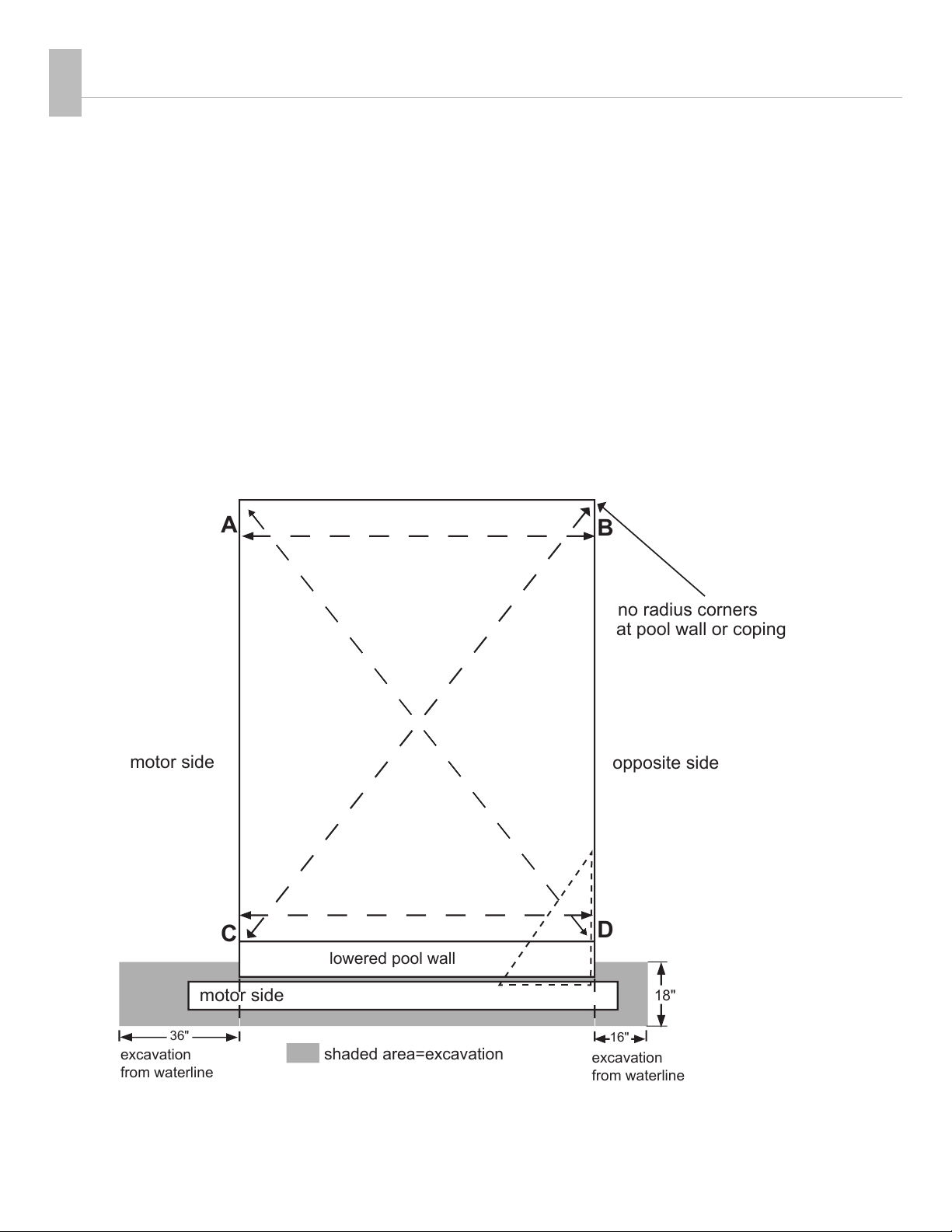
AB
no radius corners
at pool wall or coping
CD
excavation
from waterline
motor side
lowered pool wall
shaded area=excavation
opposite side
16"
36"
18"
excavation
from waterline
motor side
Recessed Mechanism—Underside™ Track or Track Channel
1. The tracks (and rectangular pools) must be a true rectangle. The tracks must be
perpendicular to the unit mechanism and recessed housing (90°).
2. Over-dig the recessed cover box end of the pool 18" beyond the forms.
Do not install plumbing within 14" of the deck in the housing area.
3. The motor can be on either end of the cover box.
4. Do not locate skimmers in the lowered pool wall.
5. All corners must be square (no radius) on the finished tile line or the coping.
6. Place 3" drain in floor or wall of recessed housing.
Pool must be square:
AB=CD
AD=CB
EXCAVATION AND PLUMBING
Consider any special requirements for excavation and plumbing.
E
FG
Track squared to box
or mechanism
GE = 6'
GF = 8'
FE = 10'
2

All diagrams are for general information. Consult installation instructions for details.
4
Recessed Mechanism—Universal, SnapTop™, or Flush Track
The requirements of a recessed mechanism with a deck-mounted track are the same as the undertrack on the previous
page. Universal track may be mounted at the pool edge. Flush track must be set back 6" from the pool edge.
C D
AB
Do not
locate track
on top of a
skimmer lid.
16"
36"
motor side
non-motor side
18"
shaded area=excavation
TRACK DIAGONALS: AD=BC
TRACK LENGTH: AC=BD
TRACK SPACE: AB=CD
1' minimum setback
2' beyond pool
Tracks must be square:
AB=CD
AD=CB
E
G
F
Track squared to box
or mechanism
GE = 6'
GF = 8'
FE = 10'

All diagrams are for general information. Consult installation instructions for details.
5
Electric Motor w/ Keyswitch (Standard Equipment)
¾hp Motor with Slip Clutch
Hydraulic Power System
(Optional)
3" poly or PVC pipe from
housing to power unit.
NO SHARP BENDS!
ELECTRICAL
Choose electric or hydraulic power and controlling devices.
All switches must be
mounted in full view of
the cover operation.
hydraulic motor
050275 or 050276
Hydraulic Pump Unit
electric motor
3
WARNING! These are minimum recommendations only. All local and federal codes of standard safe practices
must be followed. Refer to the prewiring instructions for detailed instructions and additional mounting options.
Dedicated
GFCI
Key Switch 120V
(Hot, Neutral, Ground)
(Neutral, Dir 1, Dir 2, Ground)
Pool
Cover Housing
NPT watertight connector 14 AWG Min.
Wire extended 8" past conduit end.
Conduit with three different
colored wires and one ground.
Conduit to 120 VAC 15
AMP dedicated G.F.C.I.
WARNING! These are minimum recommendations only.
All local and federal codes of standard safe practices must be followed.
36" of waterproof flex conduit with 1/2"
14 AWG under 50ft
12 AWG over 50ft
14 AWG under 50ft
12 AWG over 50ft
MOTOR
POOL
COVER HOUSING
HYDRAULIC MOTOR END
HYD PUMP UNIT
CONDUIT FOR HYDRAULIC HOSE
WITH SWEEPING BENDS
LARGE SWEEPING BENDS
Conduit to HYD pump J-box with
2 identified wires and 1 ground
Conduit With (3)
12 AWG (min)
Identified Wires
plus one ground
Conduit with (4)
18 AWG (min)
Identified Wires
for CoverLink
Wired Control
Option 1:
Key Switch KOSA
Green
LED
Red
LED Option 2:
CoverLink
Wired Control
OR
two 1/2" hoses
over 80'
3" conduit
Dedicated
GFCI
14 AWG under 50ft
12 AWG over 50ft
All switches/control pads must
be mounted in full view of the
cover operation.
Hydraulic motors must be
mounted above ground level.

All diagrams are for general information. Consult installation instructions for details.
6
Auto-Shutoff with Optional Accessory Board/AquaLink®
¾hp Motor or Hydraulic Motor
Auto-Shutoff with Accessory Board/ AquaLink® and Wireless
(Optional) -- ¾hp Motor or Hydraulic Motor All control pads must be mounted in
full view of the cover operation. Install
the accessory board in or by the
equipment room or equipment pad,
away from the cover housing.
050275 or 050276
Hydraulic Pump Unit
All switches/control pads must
be mounted in full view of the
cover operation.
electric 3/4 hp motor
electric 3/4 hp motor
Hydraulic 1-1/2 hp motor
POOL
COVER HOUSING
Conduit with (3)
18 AWG Identified
Wires for Low
Voltage Key Switch
Option 1:
Key Switch 5v
Conduit for Main Power with (3)
14 AWG Identified Wires
(Hot, Neutral, Ground)
Conduit with (4)
14 AWG Wires
For Power and (3)
18 Awg for Sensors
Conduit with (4) 18 AWG Wires
J-box
#8 Bonding Wire
Both Ends
Conduit with (4) 18 AWG (min)
Identified Wires for CoverLink
Wired Control
Green
LED
Red
LED
Option 2:
CoverLink Wired Control
OR
Install auto-shutoff away from cover housing
in or by equipment room or equipment pad
AS
ACC
Dedicated
GFCI
14 AWG under 50ft
12 AWG over 50ft
Optional Accessory Board or AquaLink
36" of Waterproof Flex Conduit
with 1/2" NPT Water Tight
Connector, Extend (4) 14 AWG
Wires 8" Past Conduit End
MOTOR
Hydraulic motors
must be mounted
above ground level.
Option 1: Auto-shutoff mounted outside housing.
POOL
COVER HOUSING
36" of Waterproof Flex Conduit with 1/2"
NPT Watertight Connector for 14 Awg
Wire Extended 8" Past Conduit End
Conduit for Main Power with (3) 14 AWG
Identified Wires (Hot, Neutral, Ground)
Auto-shutoff
#8 Bonding Wire
(Both Sides)
Green
LED
Red
LED
CoverLink Wireless
Control Pad
Install acc board away from cover housing
in or by equipment room or equipment pad
Dedicated
GFCI
AS
ACC
14 AWG under 50ft
12 AWG over 50ft
Conduit with (4) 18 AWG Wires
Optional Accessory Board or AquaLink
Receiver
Antenna
CLEAR LINE OF RECEPTION
050275 or 050276
Hydraulic Pump Unit
Hydraulic motors
must be mounted
above ground level.
All diagrams are for general information. Consult installation instructions for details.
7
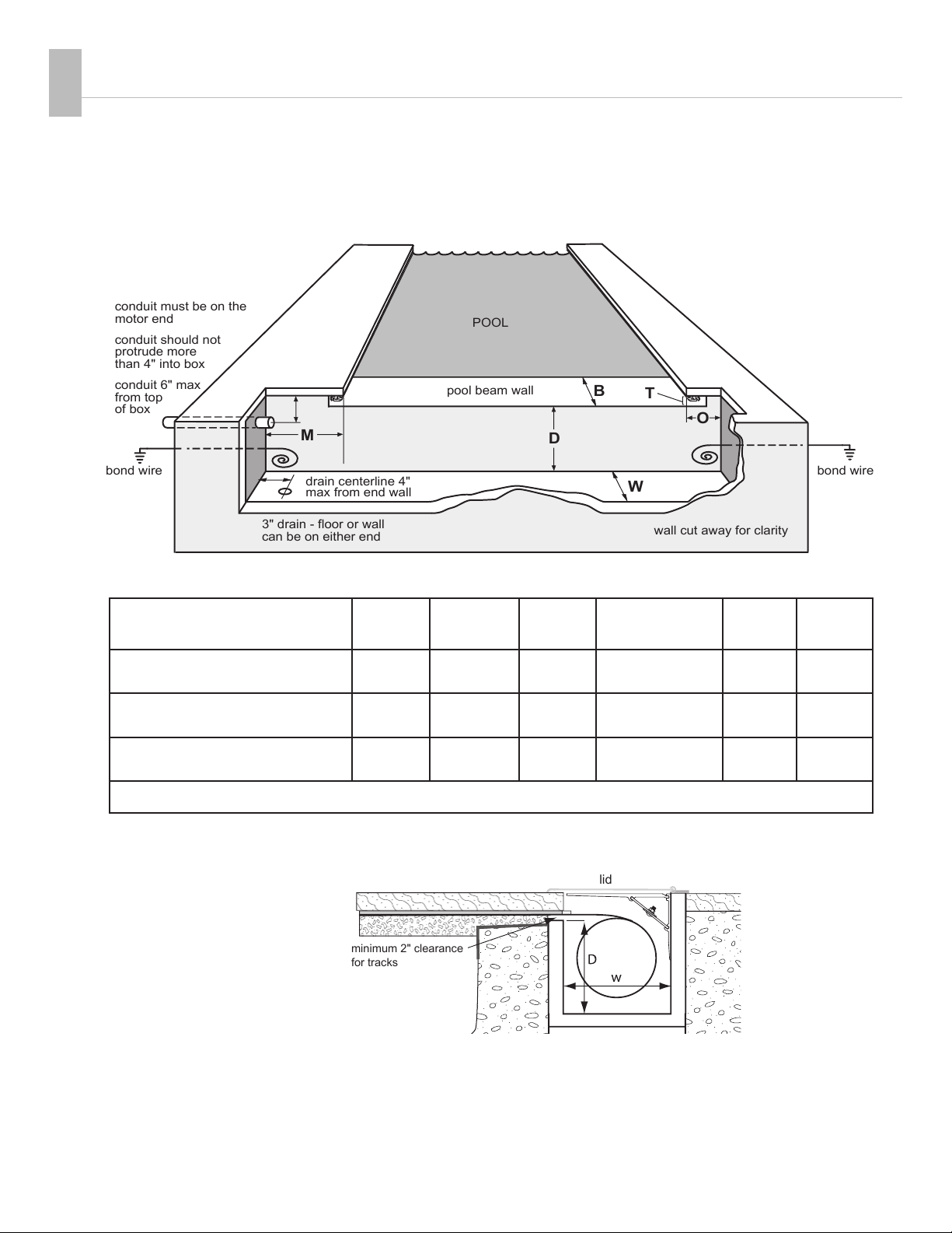
Recessed Concrete, Wood, or UPB Box—Underside™ Track
Box Side View—Underside Track
BT[
W
D
O
M
conduit 6" max
from top
of box
conduit should not
protrude more
than 4" into box
POOL
conduit must be on the
motor end
3" drain - floor or wall
can be on either end wall cut away for clarity
bond wire
pool beam wall
drain centerline 4"
max from end wall
bond wire
Optional coping or condrete build up.
lid
minimum 2" clearance
for tracks
MECHANISM HOUSING
Choose a recessed mechanism (concrete or wood box) or deck-mounted mechanism. Systems
include a lid assembly, bench frame assembly or fiberglass ends.
Underside Track
Box Dimensions for Save-T® 3
MOTOR
M
OPPOSITE
O
BEAM
B
THROAT
T
DEPTH
D
WIDTH
W
Pools under
55 ft. long x 24 ft. wide
32" 10" 8-12" 2" min to
finished beam
12-1/2"
min
12-1/2"
min
UPB BOX Pools up to
55 ft. long
32" 10" 8-12" 2" min to
finished beam
13" 13"
Pools over
55 ft. long x 24 ft. wide
32" 10" 8-12" 2" min to
finished beam
14½" 14½"
Pools over 65 ft. long or 25 ft. wide and vanishing-edge pools — Call Cover-Pools 1-800-447-2838
4
Consult a certied electrician and the pre-wiring diagrams for conduit and bonding requirements.
All diagrams are for general information. Consult installation instructions for details.
8
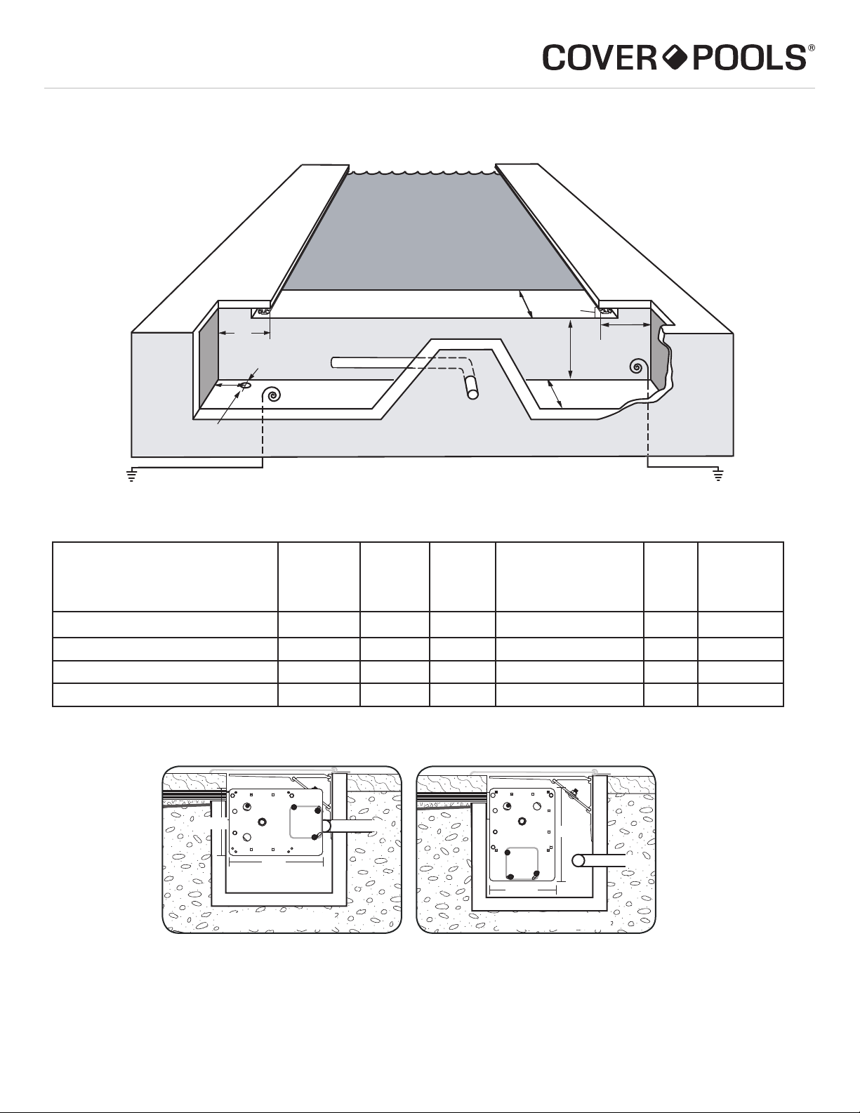
Recessed Concrete, Wood, or UPB Box—Autosave
OPTION 1: Conduit comes from back of box.
Underside Track
Box Dimensions For Autosave™
Up to 13' or
200 square feet
Motor
M
Opposite
O
Beam
B
Throat
T
Depth
D
Width
W
Motor Behind 9" min 9" min 10" min 1" to Finished Beam 9"min 12-1/2" min
w/ Auto-Shutoff 14-1/2" min 9" min 10" min 1" to Finished Beam 9"min 12-1/2" min
Motor Below 12-1/2" min 9" min 10" min 1" to Finished Beam 9"min 12-1/2" min
w/ Auto-Shutoff 12-1/2" min 9" min 10" min 1" to Finished Beam 9"min 14-1/2" min
Note: To avoid interference, run the conduit from the center of the box using flex conduit with 1/2" water tight connector.
POOL
recessed box wall
cut away for clarity
M
3" drain - floor or wall
can be on either end
D
BT
W
pool beam wall
O
drain centerline 4"
max from end wall
bond wire to bonding grid (route so that cover will not rub or catch or interfere with mechanism)
Conduit comes from
center of the housing
MTR
12"
8-1/2"
Conduit
12"
8-1/2"
Conduit
MTR
MTR
12"
8-1/2"
Conduit
12"
8-1/2"
Conduit
MTR
Motor Behind Motor Below
Side View
Consult a certied electrician and the pre-wiring diagrams for conduit and bonding requirements.

All diagrams are for general information. Consult installation instructions for details.
9
Recessed Concrete, Wood, or UPB Box—Autosave
OPTION 2: Conduit comes from side of box.
conduit should not
protrude more
than 4" into box
conduit must be as close to
rear wall as possible for
mechanism clearance.
POOL
3" drain can be on either end
recessed box wall
cut away for clarity
pool beam wall
drain centerline 4"
max from end wall
M
T
O
D
B
W
bond wire to bonding grid (route so that cover will not rub or catch or interfere with mechanism)
Underside Track
Box Dimensions For Autosave™
Up to 13' or
200 square feet
Motor
M
Opposite
O
Beam
B
Throat
T
Depth
D
Width
W
Motor Behind 9" min 9" min 10" min 1" to Finished Beam 9"min 12-1/2" min
w/ Auto-Shutoff 14-1/2" min 9" min 10" min 1" to Finished Beam 9"min 12-1/2" min
Motor Below 12-1/2" min 9" min 10" min 1" to Finished Beam 9"min 12-1/2" min
w/ Auto-Shutoff 12-1/2" min 9" min 10" min 1" to Finished Beam 9"min 14-1/2" min
MTR
12"
8-1/2"
12"
8-1/2"
Conduit
Conduit
MTR
MTR
12"
8-1/2"
12"
8-1/2"
Conduit
Conduit
MTR
Motor Behind Motor Below
Side View
Consult a certied electrician and the pre-wiring diagrams for conduit and bonding requirements.

All diagrams are for general information. Consult installation instructions for details.
10
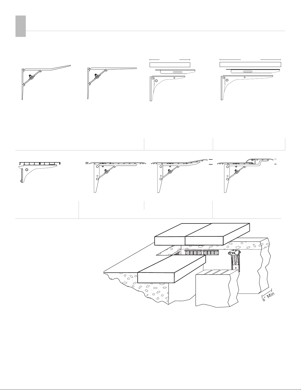
Deck-Mounted Bench Construction
Deck-Mounted Fiberglass Ends
Three-piece adjustable steel
brackets provide a maximum height
of 20" by 24" wide. Surface material
is not included.
Fiberglass ends are an economical and
practical solution to cover the deck-mounted
mechanism. Available in white.
roller tube
Recessed Wood Box Construction
Requirements:
The material used to construct the box should be:
2" x 12" pressure-treated lumber or redwood
Upper trim:
2" x 4" pressure-treated lumber or redwood
side
view
side
view
top
view
top
view
side view
14½"
12½"
14½"
36" 12"
24"
12"
to
braces
12½"
Also available with
stainless-steel base.
16¼"
to
17½"
20"
Everlast™Bench Kit Bench Frame
Modular bench kit uses adjustable-
height brackets and polymer panels
to create a low-maintenance bench
system.
Available in 4 colors
Recessed Concrete, Wood, or UPB Box—Universal or SnapTop™ Track
B
W
DO
M
POOL
conduit 6" max
from top
of box
conduit should not
protrude more
than 4" into box
conduit must be on the
motor end
3" drain - floor or wall
can be on either end wall cut away for clarity
bond wire
pool beam wall
drain centerline 4"
max from end wall
bond wire
Deck Mount Track
Box Dimensions for Save-T® 3
MOTOR
M
OPPOSITE
O
BEAM
B
THROAT
T
DEPTH
D
WIDTH
W
Pools under 55 ft. long x 24 ft. wide 32" 10" 8-12" 2" min to finished beam 12½" min 12½" min
UPB BOX Pools up to 55 ft. long 32" 10" 8-12" 2" min to finished beam 13" 13"
Pools over 55 ft. long x 24 ft. wide 32" 10" 8-12" 2" min to finished beam 14½" 14½"
Pools over 65 ft. long or 25 ft. wide and vanishing-edge pools — Call Cover-Pools 1-800-447-2838
Consult a certied
electrician and the
pre-wiring diagrams for
conduit and bonding
requirements.
All diagrams are for general information. Consult installation instructions for details.
11
Coping or Deck Requirements—Underside track
• All corners of the coping must be square
• Minimum 2" cantilever from tile
on side walls
• Minimum 3" cantilever from tile
on end wall opposite the mechanism
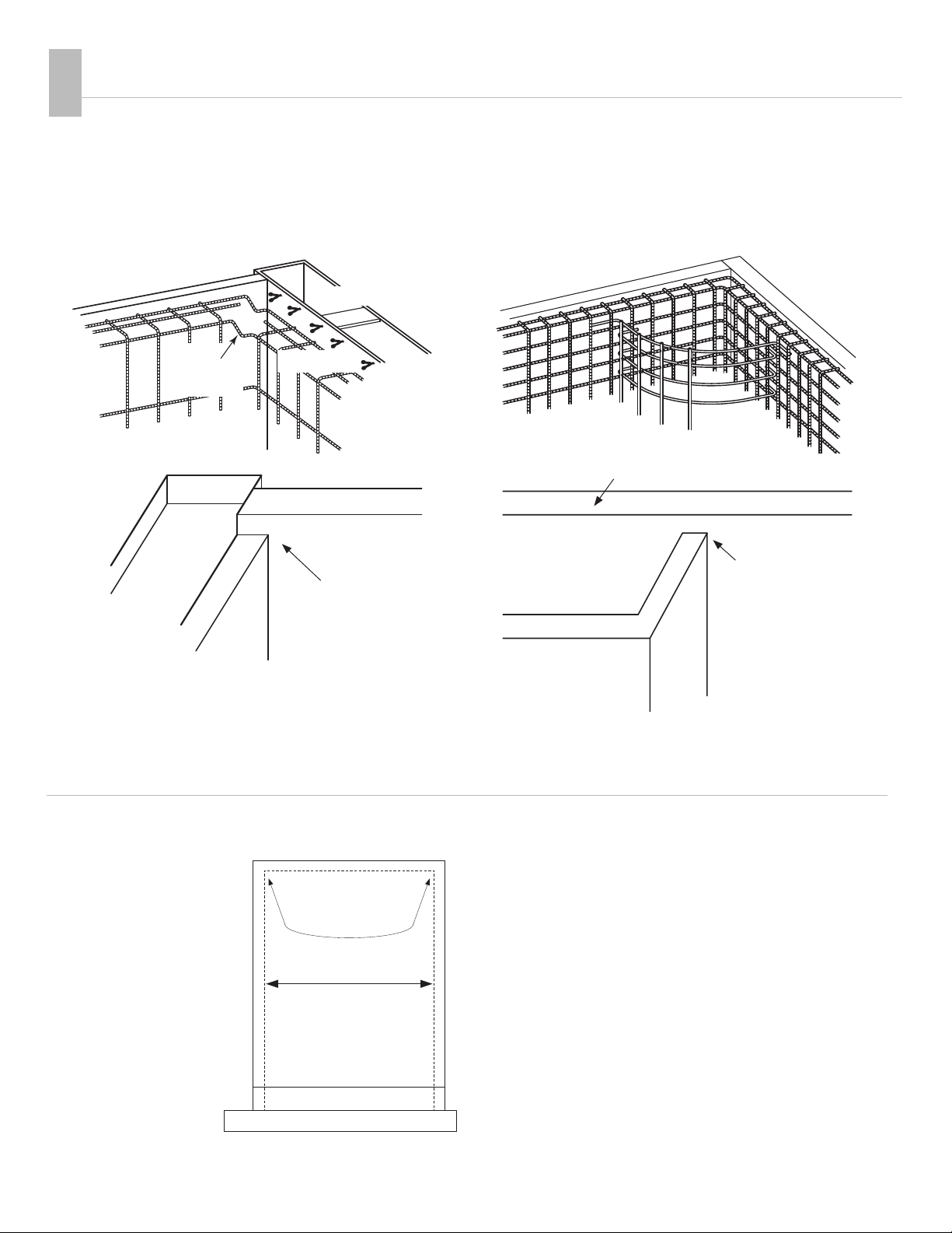
Gunite Layout—Underside™ track
At the recessed box end, the pool wall (bond beam)
must be shot 2½" (2" finished with tile) lower than
the side walls.
The top inside pool corners (above the waterline)
must be square, not radius.
Any interior wall, such as for spas, also must be gunited
2½" (2" finished with tile) lower than the side walls.
form
2½" lower
side wall
cover
box
bond
beam
top of side wall
2½" lower than
side wall
COPING AND DECK
Consider the requirements for coping and deck installation.
side wall
interior wall
form
form
brace
2" offset
in steel
16 d nails
no radius corners
2" cantilever sidewalls
lowered pool wall
motor
3" cantilever
5

All diagrams are for general information. Consult installation instructions for details.
12
Tile Beam—Underside track
1/4" round edge if exposed
1/4" round edge
POOL
DECK
2" min.
2" min.
The lowered pool wall is finished with a tile surface.
For the lowered wall edge, use a rounded tile on the front and back edges to minimize scraping on the cover.
NOTE: The track must be mounted on the flat
bottom of the coping. The coping measurement
is NOT the track space. Coping must not extend
more than ½" past the edge of the track.
Track Space
2" cantilever box minimum
12 ½" wide x 12 ½" deep
Pool wall
2" min.
bull nose
Bull nose
2" minimum
from tile
decking
Decking
DECKING
POOL WALL
2" min
2" min
from tile
TRACK SPACE
Coping or Deck Requirements—Underside track (cont.)
Opening 2" finished with
tile or other material
Opening for the track must be 2½" at box
(2" finished with tile), sloping to 3" inside pool
1/4" round edge
All diagrams are for general information. Consult installation instructions for details.
13
Vanishing Lid Adjustable 12"
Stainless-Steel Bracket
• For any tray less
than 18"
• Extensions 14½" & 17½"
available
Note: The deck thickness must be
increased for extended trays if the leading
edge is going to fit under the tray. Contact
Cover-Pools for more information.
The maximum width of any tray is 24".
The maximum length of tray is 24".
Walk-On Vanishing Lid
This design offers an adjustable tray support system for any type of
deck material. Stainless-steel or aluminum trays and stainless-steel
brackets provide the support base for a strong walk-on lid that can
blend with the surrounding deck.
Vanishing Lid Adjustable 18"
Stainless-Steel Bracket
• Maximum bracket
spacing is two feet
• For trays 18-24" wide
• Extensions 20½" & 23½"
available
Standard Aluminum Lid
Tilted Bracket
for Universal, Snaptop™,
and Flush Track
• Stepped or tilted anodized
aluminum lid available
with 4" or 6" hinge
Flush Mount Lid for vinyl
liner pools with UPB Box
NOTE:
Walk-on Vanishing Lid systems require a concrete housing,
or, if using a wood housing, a concrete wall must be poured
behind the box for anchoring brackets.
Brackets
Vanishing Lid™System
Bezel™lids
Flat Bezel Lid Tilted Bezel Lid Stepped Bezel Lid
RECESSED BOX COVER
Choose lid and brackets to cover recessed box.
Standard Aluminum Lid
Flat Bracket
for Underside™Track
• Standard anodized
aluminum lid available
with 4" or 6" hinge
18" max. 24" max.
tray or stone tray or stone
3/8" 1½
600104 ILLUS VANISHING LID CORNER BRACKET - DWG1.ai 600104 ILLUS VANISHING LID CORNER BRACKET - DWG1.ai
6"Min
1½
6
Available in 16" or 18" width
Available in 16" width
with 16" or 18" ends

All diagrams are for general information. Consult installation instructions for details.
14
SPECIFICATIONS
Review system details for Save-T®covers.
7
Quad-core™ Fabric
• Material: PVC vinyl, laminated over a reinforced
polyester mesh for strength and tear resistance
• Rigorously Tested: The exclusive formula is the
product of 50 years of testing and experience
• Designed for the Pool Environment: UV, mildew,
and pool-chemical resistant with superior
dimensional stability
• Weight: 18 oz. per square yard
• Thickness: 28 mil laminated vinyl
• Strength: Exceeds the ASTM F1346-91 minimum
standard of 485 lbs. per 4' radius
• Construction: Fabric is attached to webbing and
low-stretch rope (70,000+ cyclic loading fatigue life)
with double-sewn Dabond®bonded polyester thread for
durability
• 11 standard colors: dusky blue, royal blue, light blue,
aqua, forest green, beige, tan, brown, gray, slate gray,
and black
• Additional special-order colors available
• 7- year limited prorated standard warranty
• Sewn webbing in 9 optional colors
• Optional Ultimate™ heat sealed webbing in 6 colors
• Optional Ultimate™ rope (100,000+ cyclic loading
fatigue life) or Stainless steel cable
Track Styles
• 7-year limited warranty on all aluminum extrusions
• All aluminum extrusions are 100% anodized
• Underside™, SnapTop™, Universal, Slim™, or Flush
track
• Safety-Lock track channel
• Top-mounted track channel for concrete and
fiberglass pools
• Inverted track channel for concrete or
deck-on-deck applications
• Track channel system for vinyl pools
• Coping channel for vinyl pools
• V-Pak™ kit for vinyl pools (includes system, fabric,
channel, box, and lid)
• Reusable coping forms (3 Profiles)
• 45-degree vanishing-edge pools
• 90-degree vanishing-edge pools
• NEW Corr-Resist™ non-metallic Track Channel
Mechanism
• Exclusive Corr-Resist end hubs with stainless steel,
designed for salt water systems
• Marine-grade anodized aluminum frame and bracket
• Limited lifetime warranty
• Exclusive positive-shift system
• Exclusive Corr-Resist rope reel with stainless steel side
plates designed for quiet operation
• Standard electric system comes with either the slip
clutch or auto-shutoff
Mechanism Housing
• Standard 12" aluminum lid with either 4" or 6" hinge
• Bezel™ lids, 16" and 18" wide
• Vanishing Lid™ trays, 12"–24" wide with stainless-steel
trays and stainless-steel adjustable brackets
• Fiberglass deck-mounted mechanism end housings
• Ultimate™ Polymer recessed box
• Everlast™ modular bench kit (available in 4 colors)
• Bench frame assembly
Power and Controls
• 3-year limited warranty on all electrical
• 3/4 hp waterproof electric motor
Optional Ultimate™ High-Torque Motor
• 1 ½ hp/2000 PSI hydraulic system
• Safety lockout key control
• CoverLink™ touchpad control (wired or wireless)
• Low-voltage auto-shutoff with key switch
• Water-feature shutoff
• Jandy iAquaLink™ Interface
Safety
• Exceeds ASTM F1346-91 requirements
• Full UL listing
• Bonding included with all automatic systems
• Automatic water-removal cover pump included
• NOTE:
Some cover manufacturers treat cover pumps and
bonding as options for their systems. A solid safety
cover without a pump is NOT approved to ASTM
F1346-91 safety standards. The installation of an
automatic cover system without bonding is not a
UL-listed product.
Other Options
• Painting—all extrusions can be painted to match most
deck surfaces or fabric colors
All diagrams are for general information. Consult installation instructions for details.
15
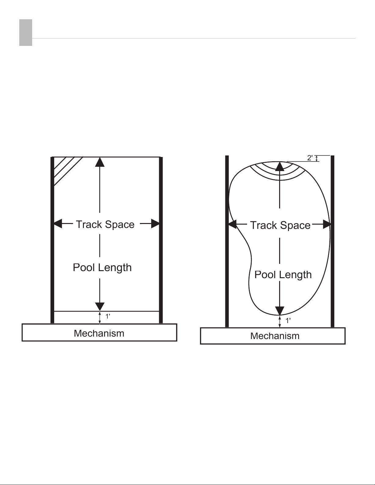
Track Space
Track Space
Pool Length
Mechanism
1'
2'
Pool Length
Track Space
Mechanism
1'
Pricing based on motor mechanism being installed one foot from pool edge, motor position on left or right.
TRACK SPACE x POOL LENGTH=COVER SQUARE-FOOT PRICING
Track widths over 25' or lengths over 65' require factory approval (maximum track space is 36').
Undertrack Deck-Mounted Track
COVER SIZING AND PRICING
Determine pricing according to the cover specifications.
8

All diagrams are for general information. Consult installation instructions for details.
16
Cost Considerations
Excavation/Plumbing
qHousing excavation
q3" drain for housing drain— drain to air
or drain to pit
q3" conduit for hydraulic-unit housing
Electrical
q1/2" Conduit for mechanism power
qElectric run to key switch
q15-amp GFCI dedicated circuit for mechanism at
panel (20 AMP for hydraulic)
qElectric runs over 50' require heavy-gauge wire
qElectrical run for accessory board
q1/2" Conduit (for low voltage wires) required with
Auto-shutoff/CoverLink wired controls
Concrete
qConcrete, gunite or shotcrete box, minimum 6" thick,
3500 PSI, (no rebound)
qAdditional deck around housing/mechanism
qTile on lower beam, beam cover or other
Cover/Mechanism
qUnit price based on track space x pool length
including steps, plus options
qTrack space 25' 6" or more may require a larger
main mechanism tube and larger leading edge
for fabric
Track
Underside™ track or Universal track standard
qTrack channel for concrete or berglass pools
(2 or 3 sided)
qFlush track
qSnapTop™ track
qVinyl-liner pool coping 90°, 45°, 6" radius or 24"
radius
qTrack channel for vinyl-liner pools
qVanishing edge 45° or 90°
qPainted track extrusions
Housing
Aluminum lid, bench frame or fiberglass ends standard
qPainted lid extrusions
qAluminum Lids: Standard, Bezel™ lids, or Flush Mount
qWalk-on Vanishing Lid™ trays
qBench for deck-mounted mechanism
Power/Controls
110 V motor and hard-wired 3-wire key standard
qAuto-shutoff control with amp limit
qWireless CoverLink™ digital touchpad control
qWired CoverLink digital touchpad control
qWater-feature shutoff/accessory board
qHydraulic pump with hydraulic hoses
qJandy iAquaLink™ interface & control

SAVE-T®3 “BIG RED”
SLIP CLUTCH
· stainless-steel and aluminum
construction
· long-wearing industrial-grade
friction material (not plastic)
· waterproof and temperature-
proof operation
· no replacement parts needed
· lifetime warranty
AquaLink®interface Board
· cover status controls pool
features
· view if cover is open/closed
· reduce the filter pump time
· adjust AquaPure output
· turn off water features, lights,
and booster pump
cleaners when the
pool is covered.
· connect to an iPhone
with the iAuquaLink™
EXCLUSIVE!
HYBRID END HUB with
CORR-RESIST™ components
· stainless steel and
Corr-Resist™ components
· designed for mineral sanitizing
systems
· minimizes salt corrosion
· can be retrofitted to previous
models
EXCLUSIVE!
MARINE-GRADE
ANODIZED ROLLER DRUM
· strong 17 gauge thick
aluminum tube
· 6" & 8" diameters available
· anodized aluminum
protects against corrosion
and oxidation
POSITIVE SHIFT SYSTEM
· all stainless-steel shaft and
shifting-dog components
· no shear pins or bolts
· 3/8" solid stainless-steel
drive dowel
NEW GLIDER STOP
· prevents glider from
running past the track
· ensures cover stops in
correct position
· attaches to track
ROLLER TUBE BRAKE
· stainless-steel
brake adjuster
· easy to adjust
· keeps cover taught
3/4 hp WATERPROOF MOTOR
· 3/4 hp, 41 rpm,
1600 in-lbs of torque
· capacitor-start, capacitor-run
· O-ring sealed and potted
wire-entry points
· stainless-steel gears with
sealed permanent grease
· UL Listed
· Optional Ultimate™ High-
Torque Motor 3/4 hp, 27 rpm,
1375 in-lbs of torque
COVERLINK™ CONTROL
· 10-number wireless or
wired touch pad
· wireless systems use
secure FM-radio
technology with signal
lock
· fits in a single gang box
· uses AA batteries
WEBBING STOP BLOCK
· simple installation to set
cover travel length
· clamp design allows
easy adjustment
KEY SWITCH
· 3-wire key switch for
simple wiring
· mounts in standard
switch box
· NEW brushed stainless
steel faceplate
(high-voltage only)
QUAD-CORE™ 18oz
FABRIC COLORS
· dusky blue
· royal blue
· light blue
· aqua
· forest green
· beige
· tan
· brown
· gray
· slate gray
· black
· Optional colored webbing
or Heat Sealed Webbing
EXCLUSIVE!
HYBRID ROPE REEL
with CORR-RESIST™
components
· Exclusive EZ-Lock rope reel
system for simple cover alignment
· choose between ratcheting or
locked rope reels
· easy adjustment on out-of-square
pools
· simple adjustment of cover alignment
· simple change-over to locked
or unlocked reels
· can be retrofitted to previous models
AUTO-SHUTOFF
WITH AMP LIMITER
· compact potted waterproof design
· adjustable amp limiter overload
safety circuit
· LED indicator and diagnostic lights
· optional water-feature control
board (can control 12- and 24-volt
motorized valves or
pump motors up to 30
amps)
LOW-STRETCH ROPE
· 70,000 cycle loading fatigue life
· attached with double-sewn,
Dabond® bonded polyester
thread.
ULTIMATE™ ROPE
· 100,000 cycle loading fatigue life
STAINLESS STEEL CABLE
· superior durability in a pool
environment
· does not stretch or shrink,
reducing realignment service
calls
This manual suits for next models
1
Table of contents
Other Cover Pools Spa Accessories manuals

Popular Spa Accessories manuals by other brands


Confer Plastics
Confer Plastics Ultra Spa Steps Assembly and instruction manual

GHARiENi
GHARiENi MLE Neo instruction manual

Novita
Novita purescent NA200 operating instructions

SPAccessories
SPAccessories Classic Lifter Installation & use manual

Leisure Concepts
Leisure Concepts Smartop Upright 2.0 installation instructions

Exerpeutic
Exerpeutic Heavenly manual

SPAccessories
SPAccessories Cover Classic Lifter Installation & use manual

Watkins Wellness
Watkins Wellness UPRITE Installation

Hayward
Hayward Spa Blower owner's manual

Gecko
Gecko in.touch 2 quick start guide

DDUUEETT
DDUUEETT sonia Maia Spray manual

Hot Tub Products
Hot Tub Products ConvertaLift Installing