SPAccessories Cover Classic Lifter Instructions for use

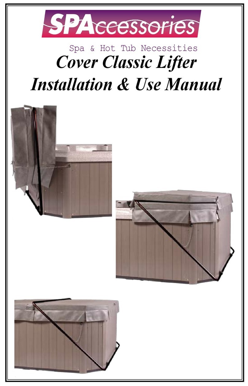
The Cover Classic Lifter adjusts to t most square/rectangular spas up
to 99” in width. When assembled it forms a rectangular shape. The
Cover Classic Lifter attaches to the back of the spa cabinet, either on the
back wall of the cabinet or on the pedestal base. The Bridge Arms (B)
lies across the spa cover parallel to the seam (hinge) of the cover and is
“captured” when the cover is folded back over it. Once the cover is folded
back, simply lift back on the Bridge Arm and the Cover Classic Lifter will
lift the cover off the spa and hold it in an upright position behind the spa.
Pilot holes are pre-drilled in the Corner Pieces (A). Once sized to your spa,
the self-tapping screws will penetrate the Bridge Arms (B) to lock the tubing
in place. Before assembling the Cover Classic Lifter, check the components
in the box against the Parts List to insure all parts are present. You will
need a power/cordless drill with Phillips bit and a tape measure.

A 4 Corner Piece
B 4 Bridge Arm
C 3 Mounting Block
D 2 Retaining Chain
E 2 Chain Bracket
32 Metal Screw #10 x ”
6 Wood Screw #8 x ”
12 Wood Screw #8 x 1¼”
F 1 Towel Holder
G 32 Screw End Caps
A
F
E
D
C
G
B

1. Lay out the components in the shape of a rectangle as shown
below (Fig A). There are 4 Corner Pieces (A). They have been
drilled so that the holes on the top and bottom of the corner
pieces are facing at a 45 degree angle on the pole when laying
at on the ground. The holes on the side of the corner pieces are
facing up when laying at on the ground.
Pre Drilled Holes on the Corner Pieces
(Perspective - Pieces laying on the ground)
On the Side areas will face up
On the Top and Bottom areas will face
45 degree outward.
Corner Piece (A)Corner Piece (A)
Bridge Arm (B)
Bridge Arm (B)
Corner Piece (A)Corner Piece (A)
Bridge Arm (B)
Bridge Arm (B)
Mounting Blocks (C)
Figure A
2. Slide Mounting Blocks (C) over the LONG SIDE of each of the
two bottom Corner Pieces (A) as shown in Fig A.
3. Slide one of the 42” Bridge Arms (B) into each of the two
Bottom Corner Pieces (A) as shown in Fig A. Repeat the process
for the Top Corner Pieces. You now have two assembled pieces,
the top and bottom sections.
4. Measure the maximum width of your spa. Slide the 2 Corner Pieces
in on the each Bridge Arm until the width matches the width of your
spa cabinet plus 3”. Be sure to slide the Bridge Arm an equal distance
into each Corner Piece. Make sure Mounting Blocks are outboard of
all screws. With the assembled pieces laying at on a level surface,
secure the Bridge Arms to the 4 Corner Pieces with the enclosed
#10 x ” self-drilling screws. Tighten all screws completely. See Fig. B.

Mounting Blocks
1.5” clearance between spa and inBridge Arm of Classic Cover Lifter
Figure B
Figure B
5. Next connect these two assembled pieces together with the last
two Bridge Arms (B) by sliding the Arms into each of the four
Corner Pieces as shown in Fig. A DO NOT secure with screws yet.
6. With the Spa Cover in place on your Spa, lay the assembled
rectangle assembly on the spa with the Mounting Blocks at the
bottom as shown in Fig. C. Remember, screws face up.
Spa Cover
Classic Cover
Lifter Bridge
Arm 1/2”
from spa
cover seam
Mounting
Blocks
Figure C
Figure C
7. Mount the Mounting Blocks as wide and as low as possible.
Attach the three Mounting Blocks to the cabinet pedestal or base
of spa cabinet if there is no pedestal, with the #8 1¼” Wood
Screws. NOTE: Mounting Blocks may be attached directly to
deck surface or use Universal Under Cabinet Bracket available
from your dealer for round, oval or octagonal spas.

8. Pull out/Push in on the top Corner/Bridge Arm assembly to adjust
the Cover Classic so that the Bridge Arm is about ½” behind the
fold seam of the spa cover as shown in Figure C. The Bridge Arm
must be parallel to the cover fold seam. Be sure to slide the Bridge
Arms an equal distance into each Corner Piece. Before you attach
the Bridge Arms into the top corners, deside which side you would
like the towel holder to be attached to. Line up the holes on the
towel holder with the holes on the side.corner pieces. Secure the
Bridge Arms to each Corner Piece with #10 x 1¼” screws. Use 3
screws per connection for all connections.
9. Center Cover Classic Lifter on spa so that there is approximately
1-½” clearance on each side between spa and the inside of Cover
Classic Lifter tubing. Screw in one #10 x ” selfdrilling metal screw
just to the outside of each Mounting Block to lock Cover Classic Lifter
into this position and prevent it from moving side to side. See Figure B.
18” clearance
behind spa
Attach retaining chain to
Classic Cover Lifter and spa cabinet
Figure D
Figure D
10. Insert one #10 x ” self-drilling metal screw through the end of one
Retaining Chain (D). Fold spa cover back and lift cover with Cover
Classic Lifter until cover is hanging vertically behind spa. Attach
Retaining Chain to OUTSIDE of Bridge Arm of Cover Classic Lifter
approximately parallel with top of spa cabinet. Tighten screw securely
but make sure that chain can move freely on screw shaft. Attach the
other end of the chain to the center hole in the Chain Bracket (F) with
a #10 x ” self-drilling metal screw. With cover hanging vertically
behind spa with about 1” between spa cover and the back of the spa
cabinet (Cover Classic Lifter will be in a slightly over-vertical position),
attach the Chain Bracket to the spa cabinet with three #8 x ” wood
screws. The Retaining Chain should be approximately parallel with the
ground, but this is NOT critical to operation. Tighten Screw securely,
but make sure chain can move freely on screw shaft. See Figure D.

SPAccessories™ warrants this product to be free from defects in
WORKMANSHIP and MATERIALS for a period of ONE YEAR. Should
a part fail under normal use within this period, SPAccessories™ will
replace the defective part(s) FREE of charge, FREIGHT PAID.
SPAccessories™ is condent in the quality of our products and dealers. If
a SPAccessories™ Authorized Dealer can validate and/or verify that a
component failure was the direct result of an unusual FACTORY DEFECT,
SPAccessories™ will support the dealer’s decision and a reasonable-
mutual corrective action shall be taken. Shocks not included.
Submit warranty claims with photo and proof of purchase to
SPAccessories™ Warranty Claim Department at WWW.888SPALIFT.COM.
The defective part may be requested to be returned freight prepaid
to SPAccessories™, 11900 N La Canada Dr, Tucson, AZ 85737. All
returns must be pre-authorized.
The obligation of SPAccessories™ under this warranty is limited
to option of replacing or repairing. Costs of repair, removal,
installation, or any consequential damage repair costs are not
provided by SPAccessories™
Warranty extends only to the original purchaser and is based
on NORMAL usage conditions. This warranty does not extend to
any damages to a product outside the control of SPAccessories™,
including freight damage, abuse, misuse, improper installation,
abnormal usage, fading with minor deteriorations caused by
exposure to the environmental factors or use of chemical substances.
SPAccessories™ is not responsible or liable for indirect or
consequential damages arising from or in connection with the use or
performance of the product.
Some states do not allow the exclusion or limitation of incidental or
consequential damages. Accordingly, the above limitation may not
apply to you. The warranty extended hereunder is in lieu of any and
all other warranties and any implied warranties. This warranty gives
you specic legal rights.
11900 N. La Canada Dr. #69792
Tucson, AZ 85737
www.888SPALIFT.com
Table of contents
Other SPAccessories Spa Accessories manuals
Popular Spa Accessories manuals by other brands

Bestway
Bestway Entertainment Station owner's manual

COVANA
COVANA LEGEND owner's manual

Leisure Concepts
Leisure Concepts Covermate Vanish XLR installation instructions

NENKO
NENKO 21893170 quick start guide

Leisure Concepts
Leisure Concepts SMARTOP SwimSpaVanish XL installation instructions

MAR PLAST SPA
MAR PLAST SPA KOMPATTO SPRAY SENSOR Use and maintenance manual