manuals.online logo
Brands
  1. Home
  2. •
  3. Brands
  4. •
  5. CoverCraft
  6. •
  7. Boating Equipment
  8. •
  9. CoverCraft Bimini Instruction manual

CoverCraft Bimini Instruction manual

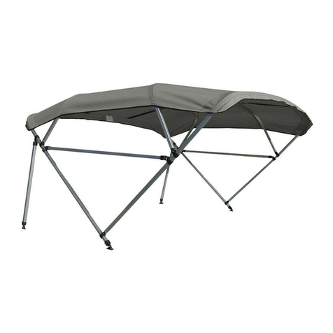
Carver Square Tube Bimini Top with Zippered Sleeves
Assembly and Installation Instructions
Carver Bimini Tops are a classy way to protect yourself and your boat from the
elements. They also add style and color to your boat. These instructions make
assembly and installation easy. Please read them carefully before beginning.
Please take extra care
when unpacking and assem-
bling your bimini top. Should
you need to return the bimini
top, it MUST be in its orignal,
new condition. The bimini
top canvas must be clean
and dry, and free of debris
(including pet hair). Frame
components must not be
scratched.
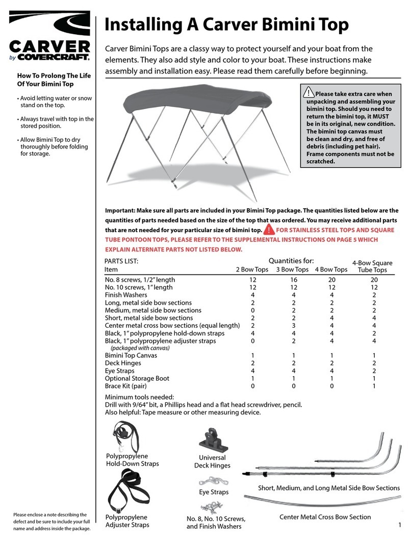
PARTS LIST:
No. 8 screws, 1/2” length 20_____
No. 10 screws, 1” length 13_____
Finish Washers 2_____
Long, metal side bow sections 2_____
Medium, metal side bow sections 2_____
Short, metal side bow sections 4_____
Center metal cross bow sections (equal length) 4_____
Black, 1” polypropylene hold-down straps 2_____
Bimini Top Canvas 1_____
Deck Hinges 2_____
Eye Straps 2_____
Optional Storage Boot 1_____
Brace Kit (pair) with following hardware: 1_____
90° Deck Hinges for Brace Kit 2_____
Quick Release Pin w/ Lanyard & Eye 2_____
ITEM: QUANTITY:
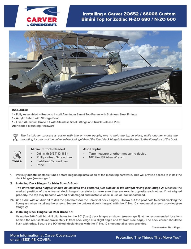
Minimum tools needed:
Drill with 9/64” bit, a Phillips head and a
flat head screwdriver, pencil.
Also helpful: Tape measure or other
measuring device.
Universal
Deck Hinges
Short, Medium, Long Metal Side Bow Secons
Center Metal Cross Bow Secon
Stainless Steel
Fasteners
Eye Straps
Packaged By ____________________________________
Carver by Covercraft Industries,
LLC
P.O. Box 399
Landrum, South Carolina 29356
(864) 457-5820
For your convenience,
Assembly and Installation Videos are
available on our website,
www.carvercovers.com
Carver products
are proudly
Made in the USA
Polypropylene
Hold-Down
Straps
Caution!
Additional Instructions for Buggy-Style
Pontoon Top with Tails:
A-Bow
B-Bow
C-Bow
Centers
A-Bow
B-Bow
C-Bows
Jaw Slides
Brace Kit
1
23
45A
6A
8
7
5B
6B
Sewn-in
tag is
on the
bottom
side
REAR
of the
canvas.
9
These instrucons show how to assemble the top, with its frame and straps,
starting upside down and inverng to an upright posion when aaching
(Note: the additional hardware (6 screw studs) is included
in the canvas package.)
1. To t tails properly, pull the tails straight down and mark the snap
locaons on the rails using a black marker.
2. Drill 1/8” hole where each snap locaon is marked on the rail
Install the supplied screw studs into each hole. Repeat for all snaps.
3. Snap tails to the rails.
to your boat.
Step 1. Idenfy the hook shaped, long A-bow, medium B-bow, and short C-
bow frame parts (as shown in gure 1). Assemble one A-Bow frame part and
one of the centers by aligning the pre-drilled holes and fastening securely
with the #8 x 1/2” screws provided (as shown in gures 2 & 3).
Step 2. Repeat this procedure for the medium and short bows, aligning the
pre-drilled holes and securing them with #8 x 1/2” screws.
Cauon: If screw heads become burred, cover heads with duct tape to
avoid damage to canvas.
Step 3. Aach hold-down strap to each medium B-Bow. Pass looped end
of the hold-down strap over the end of the B-Bow (as shown in gure 4).
Be sure adjuster buckle is facing out. Use a #8 x 1/2” screw and one nish
washer to fasten the strap to the bow at the pre-drilled hole (as shown in
gures 5A and 5B). This is easily accomplished by posioning the strap
over the pre-drilled hole and placing the nish washer around the shank of
the screw before aaching. Note: Each long A-bow has a pre-installed jaw
slide (as shown in gure 6A and 6B) to mount the rear braces (rather than a
hold-down strap).
Step 4. Connect the ends of the medium B-bows to the jaw slides located
at the ends of the long A-bows (as shown in gure 7).
Step 5. Connect the ends of one short C-bow to the remaining jaw slides on
the long A-bow. Connect the ends of the other short C-bow to the jaw slides
on the medium B-bow (as shown in gure 7). The jaw slides should allow the
short C-bows to pivot, yet be ght enough to hold securely.
Step 6. Mount the brace kit by connecng the eye ends to the remaining jaw
slides on the long A-bow (as shown in gure 7). Note: The braces are pre-
ed with deck hinges on the opposite ends for mounng to the rails on the
boat.
Step 7. Spread the Bimini Top canvas out on a clean, at surface with
the boom side up. The sewn-in label is located on the boom (or inside)
REAR of the canvas (as shown in gure 8). Unzip the sleeve zippers.
Step 8. Take the assembled frame and lay it on top of the canvas with the
long A-bow to the rear (at the sewn-in label). Fasten the zippers on the
sleeves over the short C-bows of the frame (as shown in figure 9). You are
now ready to flip the bimini top right-side up and mount to the boat (see
reverse).
Installing the Bimini Top
on the boat
to the deck hinges securely.
Please Note: The process of assembling the bimini frame may cause the width of the frame to
expand or retract at the mounting points. If the frame appears too wide or too narrow when you are
ready to mount the top on the boat, simply mount one side and, with minimal force, push or pull the
opposite side to fit the mounting point on the opposite side.
CAUTION: Always fold down and secure bimini top in
the stored position when trailering your boat.
Eye Strap Deck Hinge
Carver products
are proudly
Made in the USA
Step 2. Measure the marked posion of the
deck hinges for the main bow (long A-bow)
carefully to make sure they are exactly opposite
each other. If not aligned properly, the top may
become warped or damaged and unstable while
in use, or look unbalanced. Next, measure the
marked posions for the deck hinges for the
rear braces. These deck hinges should be locat-
ed so that the braces aach to the boat rails at
approximately 45° to 60° angles.
Step 3. Use a drill with a 9/64” bit to drill
the pilot holes for the deck hinges. Secure the
four deck hinges with the #10 x 1” sheet metal
screws provided.
Step 4. Place top on boat, aaching the
main bow (long A-bow) ends to the deck hinges
securely. Raise the top to desired upright
posion and aach the ends of the rear braces
Step 1. The Bimini Top is now ready to be
inverted and posioned on the boat. This is
easier with two or more people, one to hold the
top in place while another marks the posions
of the deck hinges to be aached to the rails of
the boat
lmportant note to Top Installer/User: Be sure all set
screws, fittings and pre-installed hardware are tight.
Vibration can cause screws to loosen over time.
Check all fittings frequently and tighten as necessary.
For your convenience, Assembly
and Installation Videos are
available on our website,
www.carvercovers.com
Carver by Covercraft
Industries, LLC
P.O. Box 399
Landrum, South Carolina
29356 (864) 457-5820
Step 5. Measure the marked posion for the
front hold-down straps by rst adjusng the
straps to a length that will aach to the boat
rails at approximately 45º to 60º angles. Mark
the posion of the eye straps on the rails of the
boat, measuring to make sure they are exactly
opposite on each side of the boat. Use a drill
with a 9/64” bit to drill the pilot holes for the
eye straps. Secure the eye straps with the
#10 x 1" sheet metal screws provided.
Step 6. Aach the snap hooks on the ends of
the front hold-down straps to the eye straps
and adjust the hold down straps as needed
so that they are as tight as possible.
fdf
Carver Industries, Inc. Limited Warranty
The materials and workmanship in Carver
products are guaranteed to be free of defects
at the time of manufacture. The length of
the warranty is determined by the type of
material ordered. Please visit our website,
www.carvercovers.com, for more information
on length of warranty for each of our bimini
top fabrics.

Other CoverCraft Boating Equipment manuals

CoverCraft CARVER Bimini Top Instruction Manual

CoverCraft

CoverCraft CARVER Bimini Top Instruction Manual

CoverCraft Carver Free Standing Pontoon Bimini Top User manual

CoverCraft

CoverCraft Carver Free Standing Pontoon Bimini Top User manual

CoverCraft Carver ZO652 Instruction Manual

CoverCraft

CoverCraft Carver ZO652 Instruction Manual

CoverCraft CARVER Bimini Top Instruction Manual

CoverCraft

CoverCraft CARVER Bimini Top Instruction Manual

CoverCraft Carver OTC User manual

CoverCraft

CoverCraft Carver OTC User manual

Popular Boating Equipment manuals by other brands

Floe VSD 8000 Assembly instructions

Floe

Floe VSD 8000 Assembly instructions

NUCANOE 3000 Assembly instructions

NUCANOE

NUCANOE 3000 Assembly instructions

Harken Unit 1 ESP installation manual

Harken

Harken Unit 1 ESP installation manual

Navnet TZ 2 touch Installation checklist

Navnet

Navnet TZ 2 touch Installation checklist

Geonav 11 Sun User and installation guide

Geonav

Geonav 11 Sun User and installation guide

Classic Accessories 05912 Instructions & Care

Classic Accessories

Classic Accessories 05912 Instructions & Care

Scott Aerator De-Icer Dock Mount Aassembly Instructions

Scott Aerator

Scott Aerator De-Icer Dock Mount Aassembly Instructions

Volvo Penta QL Boat trim system User & installation instructions

Volvo Penta

Volvo Penta QL Boat trim system User & installation instructions

GME AIS SART instruction manual

GME

GME AIS SART instruction manual

Livorsi TTK750EM Installation

Livorsi

Livorsi TTK750EM Installation

Patriot Docks JACK DOCK Assembly instructions

Patriot Docks

Patriot Docks JACK DOCK Assembly instructions

Selden Furlex 50 S manual

Selden

Selden Furlex 50 S manual

SEACHOICE 72118 user manual

SEACHOICE

SEACHOICE 72118 user manual

C. E. Smith 52100 installation instructions

C. E. Smith

C. E. Smith 52100 installation instructions

Hobie INFLATABLESTAND UP PADDLEBOARD Manual information

Hobie

Hobie INFLATABLESTAND UP PADDLEBOARD Manual information

Schenker ZEN 150 Installation, use and maintenance manual

Schenker

Schenker ZEN 150 Installation, use and maintenance manual

Lakeside 000010 Assembly & use instructions

Lakeside

Lakeside 000010 Assembly & use instructions

Ultraflex UC 128-TS Installation and maintenance manual

Ultraflex

Ultraflex UC 128-TS Installation and maintenance manual

manuals.online logo
manuals.online logoBrands
  • About & Mission
  • Contact us
  • Privacy Policy
  • Terms and Conditions

Copyright 2025 Manuals.Online. All Rights Reserved.