30
Français
Operator’s Manual
29
Français
VNUS Radio Frequency Generator
ClosureFAST
Diculty Possible Cause Corrective Action
Impedance low
(not displayed)
Saline in Device
connector and/or
receptacle
Check for presence of saline. If present, contact VNUS
Customer Service. (Note:Take care never to plug a
wet Device connector into the receptacle, as this may
damage the RF Generator.) If saline is not present in
Device connector or receptacle, perform a Saline Test
to verify functionality of Device. Replace Device or
instrument cable if Saline Test Impedance values are
out of range.
Short circuit Replace Device.
Impedance high
(not displayed)
Open circuit Check Device connection (disconnect and then re-
connect).
Table 5: RF Treatment Difficulties - ClosureRFS
ClosureRFS
Diculty Possible Cause Corrective Action
Impedance low Inadequate electrode-vein
wall contact
Improve or employ vein compression techniques.
Saline in Device connector
and/or receptacle
Check for presence of saline. If present, contact
VNUS Customer Service. (Note:Take care never to
plug a wet Device connector into the receptacle,
as this may damage the RF Generator.) If saline
is not present in Device connector or receptacle,
perform a Saline Test to verify functionality of
Device. Replace Device or instrument cable if
Saline Test Impedance values are out of range.
Short circuit Replace Device.
Impedance high Coagulum formation on
electrodes
Check Device tip for coagulum and remove as
required.
Device not in contact with
target tissue
Verify that Device is properly positioned.
Open circuit Check Device connection (disconnect and then
re-connect).
Power high Too much blood ow
Pullback rate too fast
Checkandimproveexsanguination.
Verify proper pullback rate.
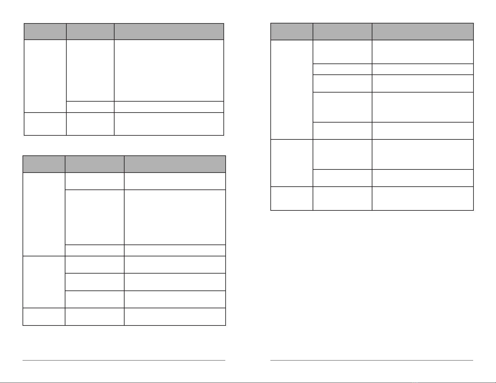
ClosureRFS
Diculty Possible Cause Corrective Action
Temperature low Inadequate vessel
exsanguination
Verify that the Device is properly positioned. Check
for ow, and employ or improve compression
techniques as necessary.
Pullback rate too fast Verify proper pullback rate.
Temperature Set Point is set
too low
Check and adjust Temperature Set Point.
Saline in Device connector Check for presence of saline. If present, contact
VNUS Customer Service. (Note: Take care never to
plug a wet Device connector into the receptacle,
as this may damage the RF generator).
Device, cable, or connector
is damaged
Check all connections, cable, and the Device for
visible damage. Replace Device.
Temperature high Saline in Device connector Check for presence of saline. If present, contact
VNUS Customer Service. (Note: Take care never to
plug a wet Device connector into the receptacle,
as this may damage the RF generator).
Temperature Set Point is set
too high
Check Temperature Set Point.
Unable to activate
RF Power
Temperature and/or
Impedance parameter
outside Functional Limits
Check Temperature and Impedance parameter
values;adjustasnecessarytobringparameters
into Functional range.
Electromagnetic Interference (EMI)
The RF Generator might cause interference that can affect other equipment. Such interference might
occur during RF Treatment Mode or during any mode that performs low power measurements, such as
Measure, Body Test, or Saline Test Modes.
If interference affects other equipment in the treatment area, move the RF Generator to a different
location and move the RF Generator cord and the Device away from the susceptible equipment and its
cords and cables.
The RF Generator is susceptible to interference from EMI emitted by other equipment. This could result in
inaccurate RF Power delivery and possible injury to the patient. Additionally, RF Treatment might halt or
the unit might restart due to a non-repeating event, such as memory corruption related to electrical or
radiation events, power surges, or power spikes.
Possible sources of EMI interference can include, but are not limited to, cellular phones, radio
transmitters, motors, telephones, lamps and other medical equipment, such as electrosurgical products
and defibrillators. Restrict the use of this equipment in the vicinity of the RF Generator.