Solar Energy
You should fasten the solar module connec-
tion cables without applying tensile stress on
the junction box.
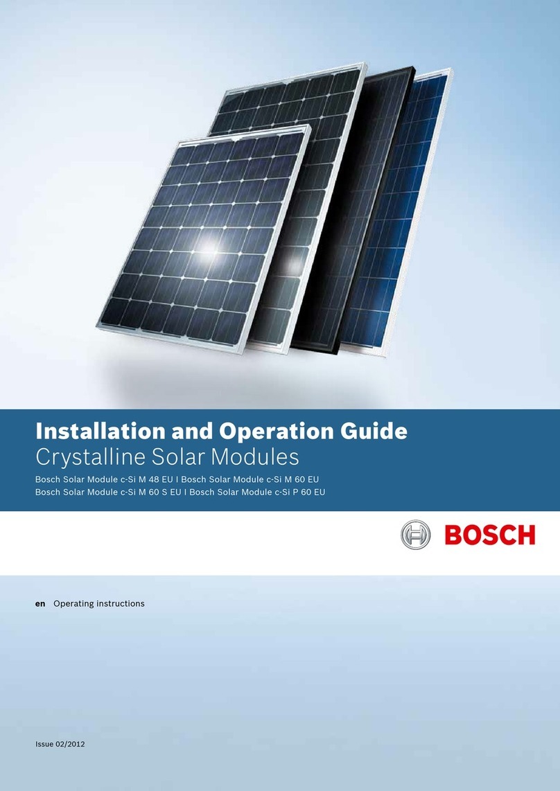
μm-Si plus EU1510 solar modules are pro-
tected by insulation (Protection Class II). As
a result, they do not have a ground wire con-
nection and do not require protective ground-
ing.
Note:
In the case of low-resistance grounding in a line con-
ductor, the overall generator voltage in the non-
grounded line conductor comes into contact with
ground potential. This is to be taken into account
when selecting and dimensioning protection systems
such as overvoltage protection.
Disconnection devices must be fitted be-
tween the module and inverter.
Cabling and disconnection elements are to
be selected and dimensioned while taking
into account external influences, such as re-
sistance to UV light and heat.
Ensure that the system does not come into
direct contact with saltwater.
Note:
Bosch Solar Energy AG does not accept any respon-
sibility for damage to equipment which has been op-
erated with Bosch Solar μm- Si plus EU1510 modules
based on information not obtained from technical data
sheets or operating instructions.
3.3 Guidelines for attaching solar
modules up to 2,400 Pa
Solar modules are a key component in a photovoltaic
system and are exposed to a wide range of mechani-
cal loads when installed. Such loads consist of sur-
face loads acting vertically to the plane, such as wind,
snow and, possibly, live loads. In the case of horizon-
tal and inclined solar modules, elements of dead load
must also be absorbed and channeled through the
fastening and support system.
In view of these considerations, Bosch a-Si plus solar
modules are to be mounted by trained specialists in
accordance with recognized technical standards while
taking into account applicable industrial standards
and regulations.
Standard DIN 1055- 4 “Action on Structures” contains
essential rules for all construction types regarding the
planning of the support framework for structures, in-
cluding their foundations, and must be observed when
dimensioning and designing the mounting and sup-
port system. IEC 61646 regulates, among other
things, the mechanical load-bearing capacity of solar
modules. The bearing capacity of solar modules for a
load of 2,400 Pa according to IEC 61646 is only
achieved if the following general instructions and
guidelines for the permanent and secure attachment
of solar modules are observed:
Solar modules must be secured in an upright
position with the junction box at the top, i.e.
laser lines should run vertically or parallel to
the slope of the roof.
Solar modules must be attached to the longi-
tudinal side along the specified clamping
sections with clamps at least 200 mm long.
Alternatively, the clamping length may be in-
creased, so that solar modules are provided
with two-sided linear support. However,
there must be a minimum support length of
200 mm to withstand both wind suction and
pressure loads. This is ensured by using suf-
ficiently stable profile sections and suitable
mechanical fasteners.
The supporting structure or substructure
must be adequately dimensioned based on a
structural analysis and adapted to the envi-
ronmental conditions locally to ensure that
the maximum permissible deflection or de-
formation under a load of L/100 is not ex-
ceeded. You also need to ensure that the
module does not distort or warp more than
30 mm across its diagonal line.
8

