COWIN.FA PLUSTEP-P User manual

1. Safety management
============================ 1
2. Products features ============================ 2
2-1) the highest Torque ============================ 2
2-2) the fastest response features ============================ 2
2-3) complete stop ============================ 2
2-4) High Speed ============================ 2
2-5) reduced motor heat ============================ 3
2-6) slim encoder ============================ 3
2-7) High Resolution ============================ 3
3. Plustep-P model and order code ============================ 4
3-1) Plustep-P model ============================ 4
3-2) ORDER CODE ============================ 4
4. Plustep-P driver specification and size ============================ 5
4-1) Driver specification ============================ 5
4-2) Driver size ============================ 6
5. Motor specification and size ============================ 7
5-2) PSM-42 SERIES ============================ 7
5-3) PSM-56 SERIES ============================ 8
5-4) PSM-60 SERIES ============================ 9
6. Motor torque characteristics ============================ 10
6-2) PSM-42 SERIES ============================ 10
6-3) PSM-56 SERIES ============================ 10
6-4) PSM-60 SERIES ============================ 10
7. Installation and wiring ============================ 11
7-1) Precaution for installation ============================ 11
8. External wiring ============================ 12
9. Setting and operation ============================ 13
9-1) Status display LED ============================ 14
9-2) Pulse input mode setting switch (SW3-1) ============================ 15
9-3) Motor rotation direction switch (SW3-2) ============================ 15
9-4) Resolution setting switch (SW1) ============================ 16
9-5) Imposition value setting switch (SW2) ============================ 16
9-6) Position-gain setting switch (SW4) ============================ 17
9-7) Input-output signal connector (CN5) ============================ 18
9-8) Encoder connector (CN6) ============================ 18
9-9) Motor connector (CN1) ============================ 19
9-10) Power connector (CN10) ============================ 19
10. System configuration ============================ 20
10-1) Optional cable ============================ 20
11. Control input and output ============================ 21
11-1) Input signal ============================ 21
11-2) Output signal ============================ 22
12. Appendix ============================ 23
12-1) Connection diagram of intermediate cable for motor ============================ 23
12-2) Connection diagram of intermediate cable for encoder ============================ 23
12-3) Internal parameter setting program ============================ 24
Table of contents
5-1) PSM-28 SERIES
6-1) PSM-28 SERIES
============================ 7
============================ 10
0
WWW.COWINFA.COM

Please be sure to fully understand the manual before using this product.
1-1) This product is used to drive a step motor. There is no guarantee for the safety
if it is used for other purposes.
1-2) Please keep the following operating environment.
① The power of this product is DC +24 V and it should be used within the input range of
± 10%. Please be careful about excessive input or reverse input.
② This product is intended to be suitable for the industry standard electromagnetic environment.
③ This product should be used within 0 ℃ ~ 50 ℃ temperature and the storage temperature
④ This product should be used within the humidity of 35% ~ 85% RH and
1-3) Please be careful on the following points when installing.
① Please remove the power plug during installation or maintenance of this product.
② Please install all connecting parts such as power plugs only when this product is firmly fixed.
③ Please turn on the power only after the product is completely installed.
④ Please turn on the power only after the product is completely installed.
⑤ The arbitrary modification by an user is outside the warranty and the company will not be liable for it.
1. Safety management
is between -20 ℃ and 70 ℃.
stored within the humidity of 10% ~ 90% RH without condensation.
1
WWW.COWINFA.COM

2. Product Features
2-1) The highest torque
It can be operated with torque
at maximum 30% higher
in the area of its class.
2-2) The quickest response feature
It has the quickest response feature
with more than 20% faster
2-3) Complete stop
PluStep completely stops after stop
and therefore, does not
generate subtle vibration.
2-4) High Speed
PluStep can work without any out-of-phase
in the area of high speed because
the high torque occurs for 100% load
by having monitored the current position
with encoder feedback.
than its class.
2
WWW.COWINFA.COM
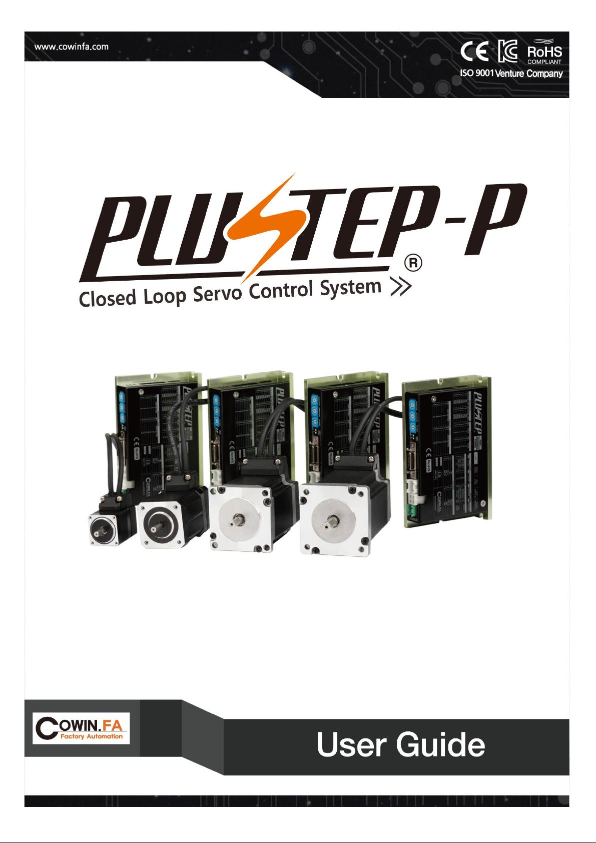
2-5) Reduced motor heat
PluStep has achieved low heat compared to high torque by applying our proprietary technology.
2-6) Slim Encoder
The slim design of encoder minimizes the total length of motor.
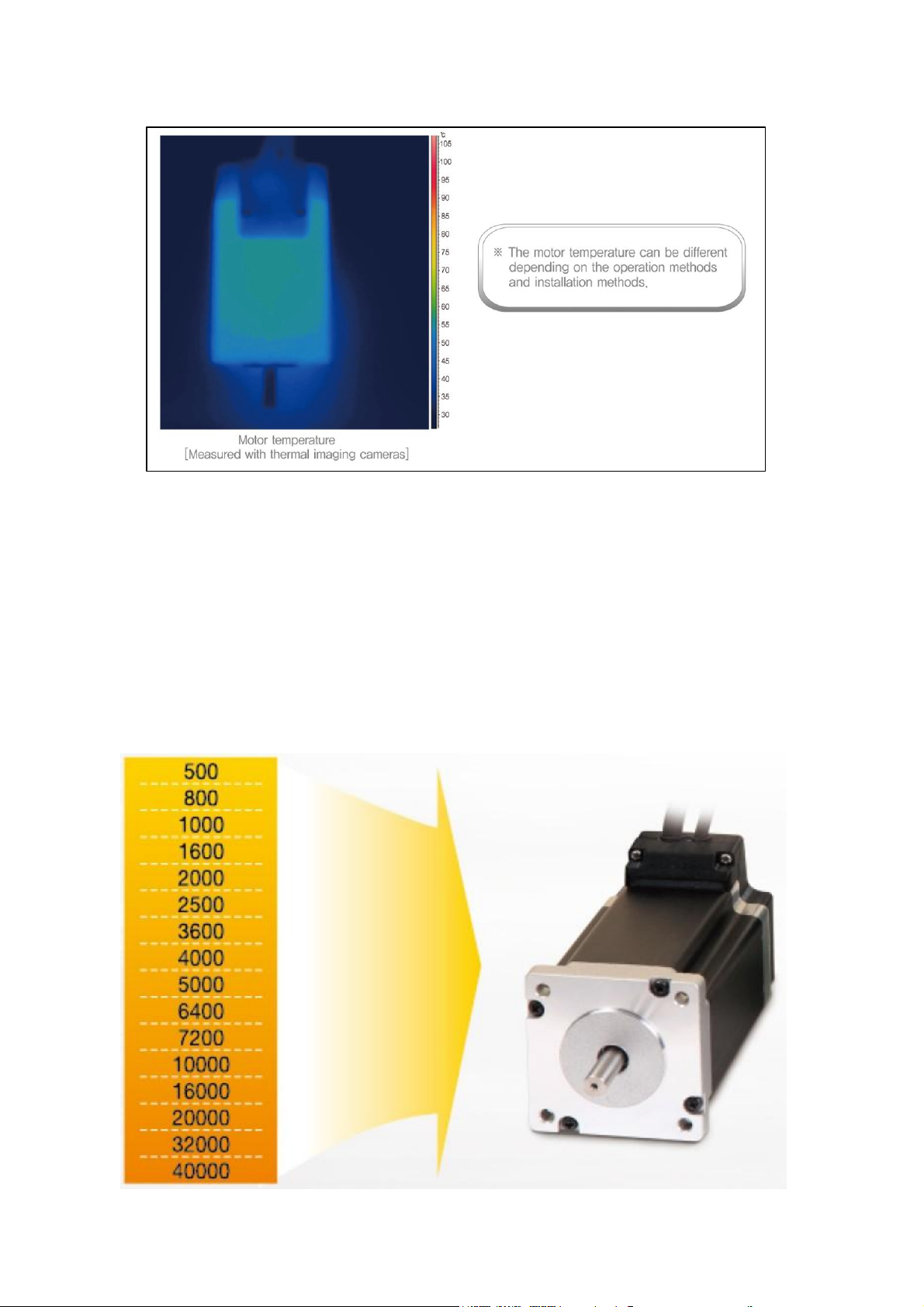
2-7) High Resolution
Plustep uses a high degree encoder executable 40,000 resolution/rotation of the basic specification
and therefore, it can be used at no additional cost according to the existing encoder pulse options.
(Maximum 40,000 pulses/rotation)
3
WWW.COWINFA.COM
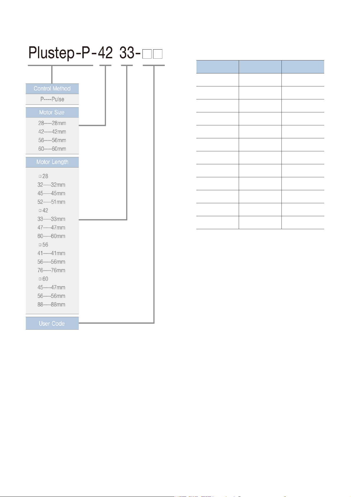
3-1) Plustep-P model
3. Plustep-P model and order code
3-2) ORDER CODE
Motor model
Driver name
PLUSTEP-P-2832
PSM-2832
PSD-2832
PLUSTEP-P-5656
PLUSTEP-P-5676
PSM-2845
PSM-2852
Unit name
PSM-4233
PSM-4247
PSM-4260
PSM-5641
PSM-5656
PLUSTEP-P-2845
PLUSTEP-P-2852
PLUSTEP-P-4233
PLUSTEP-P-4247
PLUSTEP-P-4260
PLUSTEP-P-5641
PSM-5676
PSD-2845
PSD-2852
PSD-4233
PSD-4247
PSD-4260
PSD-5641
PSD-5656
PSD-5676
PSD-6045
PSD-6056
PSD-6088
PLUSTEP-P-6045
PLUSTEP-P-6056
PLUSTEP-P-6088
PSM-6045
PSM-6056
PSM-6088
4
WWW.COWINFA.COM

4. PluStep-P driver specification and size
4-1) Driver Specification
PSM-2832 PSM-2845 PSM-2852 PSM-4233 PSM-4247 PSM-4260 PSM-5641 PSM-5656 PSM-5676 PSM-6045 PSM-6056 PSM-6088
PSD-2832 PSD-2845 PSD-2852 PSD-4233 PSD-4247 PSD-4260 PSD-5641 PSD-5656 PSD-5676 PSD-6045 PSD-6056 PSD-6088
Input voltage
Current
consumption
Temperature
Humidity
Vibration
Rotational
speed
Maximum
input frequency
Protective
function
LED display
Imposition
setting
POSITION GAIN
Pulse input
method setting
Motor rotational
direction setting
Speed/position
control
command
Input signal
Input,
output
Output signal
Functions
1 – 16 (set by rotary switch)
1 clock, 2 clock DIP switch setting
Abnormalities such as overheating, low voltage, over-speed, speed difference, over-current
Power supply (Green), alarm (Red), Inposition (Orange), Servo On (Blue)
0 – 15 (set by rotary switch)
Encoder signal (A+, A-, B+, B-, Z+, Z-) (Output through relevant AM26LS31)
Motor rotational direction setting by DIP switch
Pulse input (Photo coupler)
Servo on / off, alarm reset, position command pulse (Photo coupler)
Alarm out, imposition out (Photo coupler)
24VDC ±10%
Applicable motor
Driver type
Environ
ment
500KHz (duty50%)
500, 800, 1000, 1600, 2000, 2500, 3600, 4000, 5000, 6400, 7200
10000, 16000, 20000, 32000, 40000 (set by rotary switch)
Maximum 1A (excluding motor current)
In use: 0 ~ 50 °C, In storage: -20 ~ 70 °C
In use: 35 ~ 85 % RH, in storage: 10 ~ 90 % RH
0.5G
0 ~ 3,000RPM
Resolution
5
WWW.COWINFA.COM

4-2) Driver size
6
WWW.COWINFA.COM

5-1) PSM-28 SERIES
5. Motor specification and Size
UNIT PSM-2832 PSM-2845 PSM-2852
---
---
VDC 3.8 4.56 6.2
A 0.67 0.67 0.67
Ohm 5.6 6.8 4.9
mH 3.4 4.9 7.2
N.m 0.059 0.093 0.117
g-㎠912 18
kg 0.11 0.14 0.2
℃
mm
32±1 45±1 51±1
M O D E L
DRIVE METHOD
BI-POLAR
NUMBER OF PHASES
2
VOLTAGE
CURRENT per PHASE
RESISTANCE per PHASE
INDUCTANCE per PHASE
HOLDING TORQUE
ROTOR INERTIA
WEIGHTS
AMBIENT TEMPERATURE
-20℃ ~ +50℃
LENGTH (L)
7
WWW.COWINFA.COM

5-2) PSM-42 SERIES
UNIT PSM-4233 PSM-4247 PSM-4260
---
---
VDC 2.76 3.84 8.76
A 1.2 1.2 1.2
Ohm 2.3 3.2 7.3
mH 3.4 6 16.6
N.m 0.32 0.54 0.68
g-㎠35 68 102
kg 0.22 0.35 0.5
℃
mm
33.5±1 47.5±1 60±1
M O D E L
HOLDING TORQUE
ROTOR INERTIA
INDUCTANCE per PHASE
RESISTANCE per PHASE
CURRENT per PHASE
WEIGHTS
LENGTH (L)
AMBIENT TEMPERATURE
BI-POLAR
2
-20℃ ~ +50℃
VOLTAGE
NUMBER OF PHASES
DRIVE METHOD
8
WWW.COWINFA.COM

5-3) PSM-56 SERIES
UNIT PSM-5641 PSM-5656 PSM-5676
---
---
VDC 2 2.5 3.2
A 2.8 2.8 2.8
Ohm 0.7 0.9 1.13
mH 1.4 2.5 3.6
N.m 0.55 1.26 1.7
g-㎠131 400 480
kg 0.37 0.7 1
℃
mm 41 56 76
HOLDING TORQUE
ROTOR INERTIA
CURRENT per PHASE
RESISTANCE per PHASE
INDUCTANCE per PHASE
M O D E L
DRIVE METHOD
BI-POLAR
NUMBER OF PHASES
2
VOLTAGE
WEIGHTS
AMBIENT TEMPERATURE
-20℃ ~ +50℃
LENGTH (L)
9
WWW.COWINFA.COM
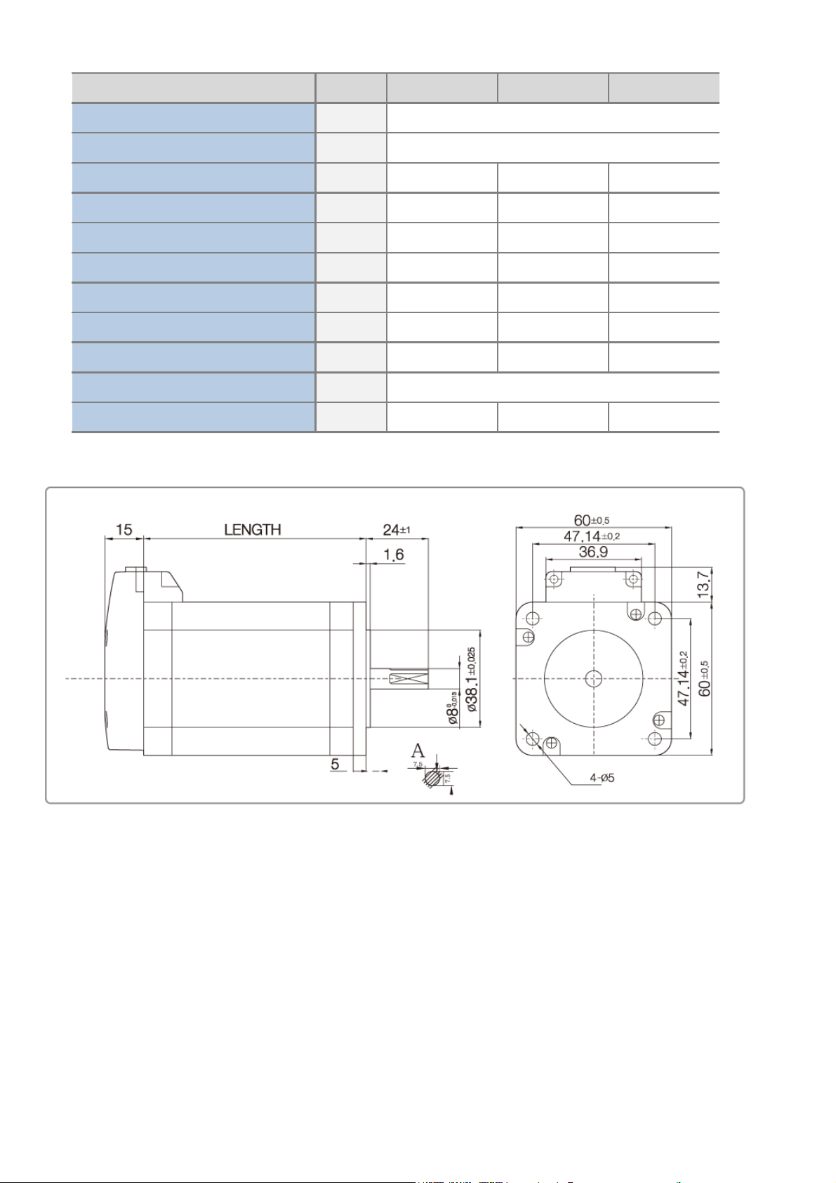
5-3) PSM-60 SERIES
UNIT PSM-6045 PSM-6056 PSM-6088
---
---
VDC 1.36 1.6 2.8
A 4 4 4
Ohm 0.34 0.4 0.7
mH 0.8 1.38 3.5
N.m 1 1.4 2.4
g-㎠275 400 840
kg 0.6 0.77 1.4
℃
mm
47±1 56±1 88±1
NUMBER OF PHASES
2
M O D E L
DRIVE METHOD
BI-POLAR
WEIGHTS
AMBIENT TEMPERATURE
-20℃ ~ +50℃
LENGTH (L)
VOLTAGE
CURRENT per PHASE
RESISTANCE per PHASE
INDUCTANCE per PHASE
HOLDING TORQUE
ROTOR INERTIA
10
WWW.COWINFA.COM

6. Motor torque characteristics
6-1) PSM-28 SERIES
6-2) PSM-42 SERIES
Speed(RPM)
1011021033x103
0
200
300
400
500
600
700
Torque(mN . m)
PSM-4260
PSM-4247
PSM-4233
11
WWW.COWINFA.COM
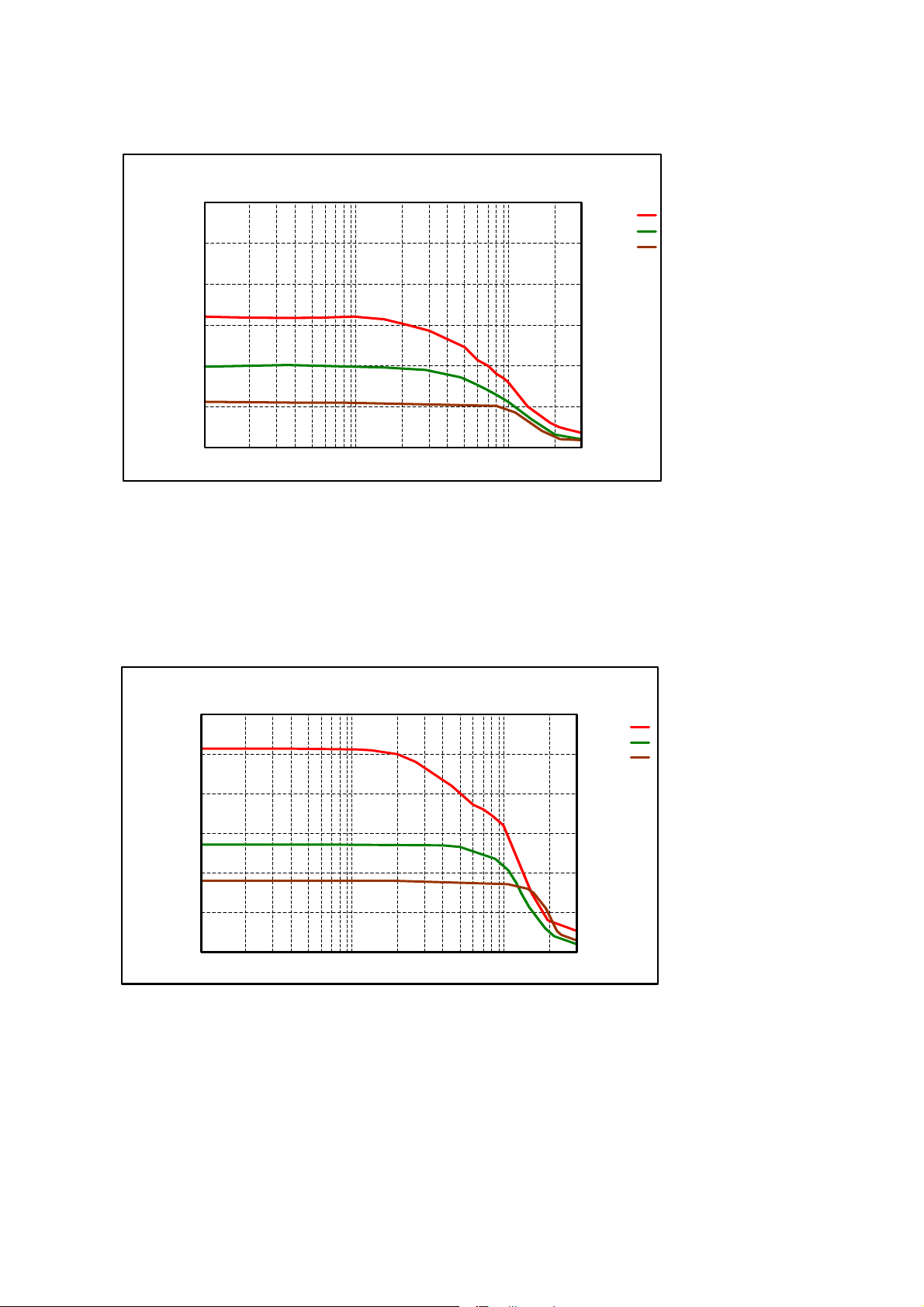
6-3) PSM-56 SERIES
6-4) PSM-60 SERIES
Speed(RPM)
1011021033x103
0
0.5
1
1.5
2
2.5
3
Torque(N . m)
PSM-5676
PSM-5656
PSM-5641
Speed(RPM)
1011021033x103
0
0.5
1
1.5
2
2.5
3
Torque(N . m)
PSM-6088
PSM-6056
PSM-6045
12
WWW.COWINFA.COM

7. Installation and wiring
7-1) Installation and wiring
① It should be used only at the room ambient temperature of 0 ℃ ~ 50 ℃.
② When the case is over 50 ℃, the heat should be dissipated to the outside.
③ It should be installed away from direct sunlight, magnetic or radioactive objects.
④ When installing more than 2 drivers in parallel, they should be installed with the distance
of more than 20mm vertically and 50mm horizontally as shown in the figure below.
More than 50mm
More than 20mm
13
WWW.COWINFA.COM
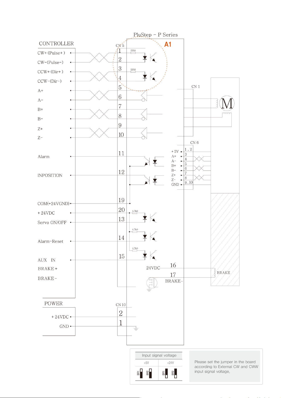
8. External wiring diagram
14
WWW.COWINFA.COM

9. Setting and Operation
Status Display
LED
Resolution setting
switch (SW1)
Inposition value
setting switch (SW2)
PO-Gain setting
switch (SW4)
Pulse input setting and
rotational direction
convert switch (SW3)
Input/output signal
connector (CN5)
Encoder connector (CN6)
Motor connector (CN1)
Power connector (CN10)
Green
Red
Blue
Orange
4
TX
RX
GND
Number
Functions
1
+5V
2
3
15
WWW.COWINFA.COM

9-1) Status display LED
① Status display LED function and lighting condition.
② Protection function contents and number of LED flashing
Color Function Lighting condition
Green Power input display Lighting when the power is turned on
Red Alarm display
Flickering when the protection function is activated (The
contents of activated protection function can be known
by number of flickering)
Blue Servo On /Off Servo ON: lighting, Servo OFF: lights-out
Orange
Positioning completion
signal display
Lighting when position deviation from the target position
is within the value set by the rotary switch (SW2) after
having completed the position command pulse input.
Number of LED
flashing
Name of Error Description
1Over-current When the current exceeds the set limit
2Over-speed When the speed exceeds the set limit
3Overload
When the motor torque exceeds the set limit for
more than 5 seconds
4Overheating Drive internal temperature exceeds 55 ℃
5Low current Motor supply voltage is less than the lower limit
6
Motor
connection error
Motor connection error
7
Encoder
connection error
Encoder connection error
8Location tracking
Command during operation and actual position
exceed 90 degrees
9
Position error
exceeds
The error exceeding 90 degrees occurs when
Motor stops
10 Inposition error
Error exceeding 1 after completion of operation
occurs for more than 3 seconds
11 Input pulse error
When the input pulse exceeds the limit
frequency
12 System fault Drive system error (MCU)
13 EEPROM error When parameter storage device error occurs
14
Default in motor
setting
Motor select error
15 Servo on error
In case input pulse is supplied
before completion of Servo ON
16
WWW.COWINFA.COM
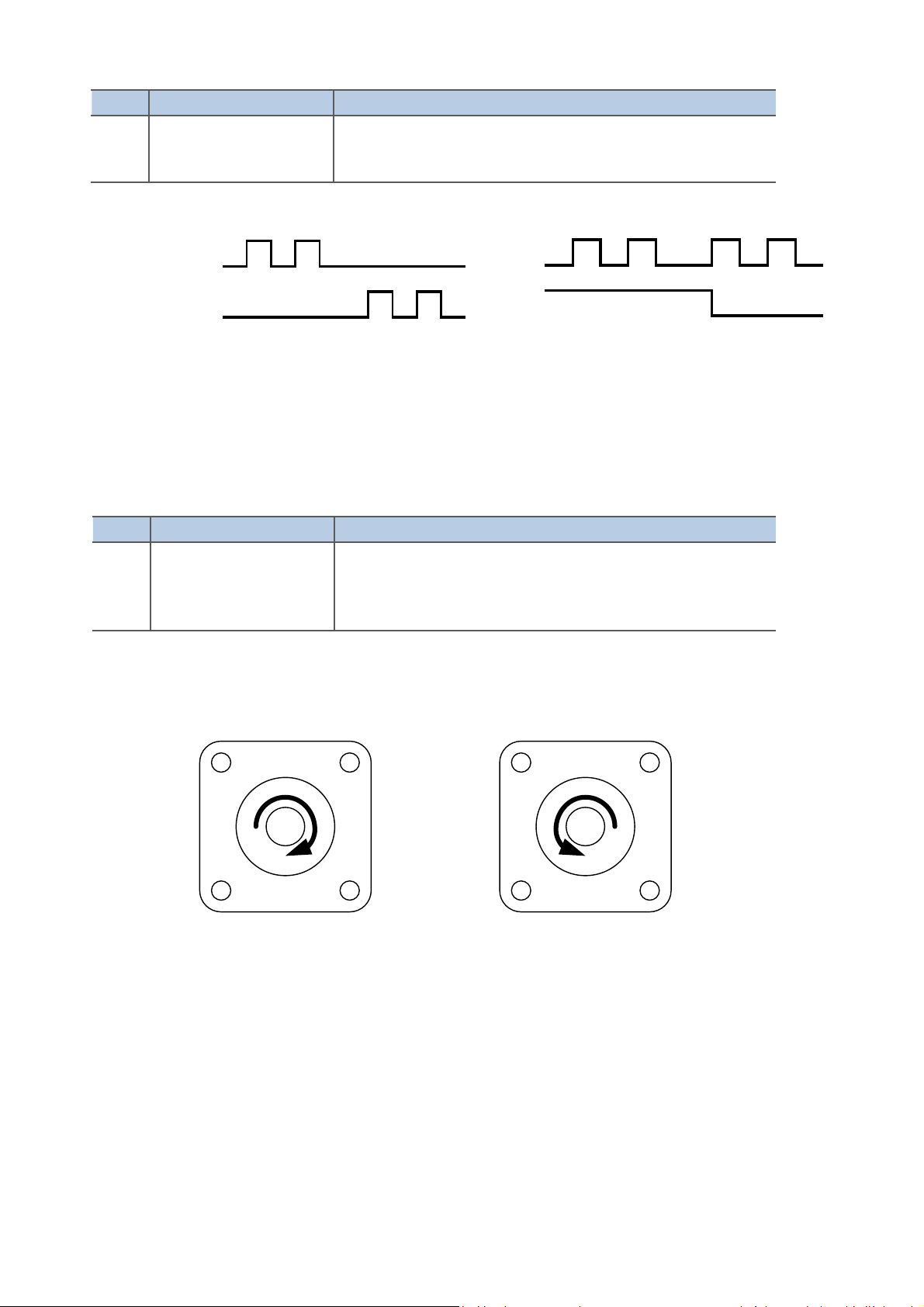
9-2) Pulse input mode setting switch (SW3-1)
9-3) Motor rotation direction switch (SW3-2)
CW(Pluse) Pin
CCW(Dir) Pin
Rotational Direction
CW
CCW
CW
CCW
CW Direction
CCW Direction
Display
Switch name Function
1CLK/
2CLK
Motor rotation
direction selection
Driver CW (+ Dir signal) input basis.
SW3-2 ON: CCW (- Direction)
SW3-2 OFF: CW (+ Direction)
※ CW is set at the time of shipping
Display
Switch name Function
1CLK/
2CLK
Pulse input
mode selection
Pulse input mode can be selected One Pulse or Two Pulse.
SW3-1 ON: Pulse One Pulse input mode
SW3-1 OFF: Pulse Two Pulse input mode
M M
17
WWW.COWINFA.COM

9-4) Resolution setting switch (SW1)
It refers to the number of pulses sent from the host controller per one rotation of the motor.
9-5) Inposition value setting switch (SW2)
It indicates the output conditions of positioning completion signal. If the position deviation from
the target position is less than the set inposition value after the completion of position command
pulse, the positioning completion signal is output.
NO
Pulse / Rotation NO Pulse / Rotation SW1
0500 85000
1800 96400
21000 A7200
31600 B10000
42000 C16000
52500 D20000
63600 E32000
74000 F40000
NO Inposition NO Inposition SW2
0088
1199
22A10
33B11
44C12
55D13
66E14
77F15
18
WWW.COWINFA.COM
This manual suits for next models
12
Table of contents
Popular Control System manuals by other brands


Skov
Skov FarmOnline+ DataLink 131545 Technical user guide

roco
roco 10810 quick guide

Wigersma & Sikkema
Wigersma & Sikkema UNICOM 300 Installation and user manual

CNC Router Parts
CNC Router Parts CRP4896 Assembly instructions

Lindsay
Lindsay Barrier Systems X-LITE installation manual

Express
Express ASX-31003-C Installation, operating and maintenance instructions


