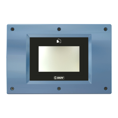
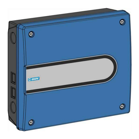
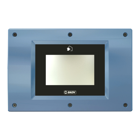
Skov FarmOnline+ DataLink 131545 Manual

FarmOnline+ DataLink
Technical User Guide
604432 • 2021-12-20 Software version 1.0
English For other language variants of this document we refer to:
Español Para otras variantes del idioma de este documento, visite:
Français Pour les versions dans d'autres langues de ce document veuillez consulter:
http://docs.skov.com/1253


FarmOnline+ DataLink
Technical User Guide 3
Product and Documentation Changes
SKOV A/S reserves the right to change this document and the product herein described without further notice.
In case of doubt, please contact SKOV A/S.
The date of change appears from the front and back pages.
Note
• All rights belong to SKOV A/S. No part of this manual may be reproduced in any manner whatsoever without
the expressed written permission of SKOV A/S in each case.
• All reasonable efforts have been made to ensure the accuracy of the information contained in this manual.
Should any mistakes or imprecise information occur in spite of this, SKOV A/S would appreciate being noti-
fied thereof.
• Irrespective of the above, SKOV A/S shall not accept any liability with regard to loss or damage caused or
alleged to be caused by reliance on any information contained herein.
• Copyright by SKOV A/S.

FarmOnline+ DataLink
Technical User Guide
1 Product description........................................................................................................................................5
2 Mounting guide...............................................................................................................................................6
2.1 Recommended tools.................................................................................................................. 6
2.2 Mounting on the wall ................................................................................................................. 6
3 Installation guide ............................................................................................................................................8
3.1 Electrical connection................................................................................................................. 8
3.2 Connection of network .............................................................................................................. 8
3.3 Connection of input sensors .................................................................................................... 8
3.4 Connection of power supply................................................................................................... 10
3.4.1 Setting the supply voltage on the power supply......................................................................... 11
3.5 Connection of external antenna ............................................................................................. 11
4 Setup..............................................................................................................................................................13
4.1 Setup ......................................................................................................................................... 13
4.2 Setup of input sensors ............................................................................................................ 14
4.3 Settings..................................................................................................................................... 15
5 User guide .....................................................................................................................................................17
5.1 Batch ......................................................................................................................................... 17
5.2 Input sensors ........................................................................................................................... 18
6 Maintenance..................................................................................................................................................19
6.1 Recycling/Disposal .................................................................................................................. 19
7 Troubleshooting instructions......................................................................................................................20
8 Technical data...............................................................................................................................................21
FarmOnline+ DataLink
Technical User Guide 5
1 Product description
This guide deals with the installation and connection of the FarmOnline+ DataLink.
The layout of the manual follows the work routines required. By following the instructions of the manual, you will
go through all steps in the correct order.
FarmOnline+ DataLink is developed for data collection in various parts of the agricultural industry. This can be
automatic collection from input sensor e.g. temperature sensors and/or the user's manual entries of data. The
collected data is then made available to the digital service FarmOnline+.
DOL 114
DOL 114
DOL 12
DOL 53
Figure1: Example of a system with FarmOnline+ DataLink.
131545 FarmOnline+ DataLink EU
131546 FarmOnline+ DataLink CN
131547 FarmOnline+ DataLink AP
131548 FarmOnline+ DataLink NF
131549 FarmOnline+ DataLink LA
Inputs (11). Of which 3 inputs are digital and 5 of the inputs can be con-
nected to DOL 12.
The device is supplied in 5 variants with different types of modems intended
for different geographical areas.
EU: Europe, the Middle East and Africa
CN: China and India
AP: Asia and the Pacific region
NF: North America
LA: Latin America
Order the correct version for your country. If necessary see 4G Modem
Country list.
Is supplied with modem with SIM card and external antenna.
Cables are not supplied.
Accessories
134703 M25 cable glands (30 pcs.)

FarmOnline+ DataLink
6 Technical User Guide
2 Mounting guide
2.1 Recommended tools
A list of the recommended tools for mounting purposes can be seen below.
Item Description
Crosshead screwdriver
Screwdriver straight slot (2 pcs.)
Hammer
Tape measure
2.2 Mounting on the wall
The FarmOnline+ DataLink must be installed where it is not exposed to frost or direct sunlight.

FarmOnline+ DataLink
Technical User Guide 7
1. Loosen the screws (A) that hold the front panel in place.
2. Lift out the front panel.
3. Be careful not to pull the flat cable (B), as this may damage the connector.
4. Knock out the number of knock-out pieces (C) in the cabinet base needed for input sensors and mains sup-
ply.
5. Remember to use M25 glands in order to obtain a tight cable connection.
6. Place the display (D) at eye level for the daily user.
7. Remember free space:
- above the cabinet (43 cm), so that the front panel can be placed on top of the cabinet base (E) during ser-
vicing.
- below the cabinet (10 cm) to enable room for cable connections.
8. Mount with Ø5mm screws (F).

FarmOnline+ DataLink
8 Technical User Guide
3 Installation guide
The FarmOnline+ DataLink must be connected to cables for input sensor, power supply and any Ethernet net-
work.
3.1 Electrical connection
Installation, servicing and troubleshooting of all electrical equipment must be carried out by quali-
fied personnel in compliance with the applicable national and international standard EN 60204-1
and any other EU standards that are applicable in Europe.
The installation of a power supply isolator is required for each motor and power supply to facilitate
voltage-free work on the electrical equipment. The power supply isolator is not included.
3.2 Connection of network
If a Local Area Network (LAN) is available, we recommend connecting the device to this to obtain Internet con-
nection. Otherwise the device will use the built-in 4G modem to communicate via the Internet.
Connect an Ethernet cable to the network connector LAN1, which is located on the CPU module in the cabinet
cover.
Figure2: Cabinet cover with CPU module.
3.3 Connection of input sensors
The FarmOnline+ DataLink can be connected to up to 11 input sensors of the following type:
Input sensor Limit value (gives direct data transmission)
Conveyor run time counter
DOL 114 (humidity) 1 %
DOL 114 (temperature) 0.5 °C
DOL 12 (temperature) 0.5 °C
DOL 19 (CO2) 20 ppm
DOL 53 (NH3) 1 ppm
Feed weigher DOL 99A (5 kg per pulse) 0.1 t
Feed weigher DOL 99A (25 kg per pulse) 0.1 t
Water meter (max. 4 pulses per second) 0.1 m3
It collects data from input sensors once every minute.
Data is sent at least once every 5 minutes. However, a value is sent immediately if the difference to the last
read value is greater than the limit value.

FarmOnline+ DataLink
Technical User Guide 9
Figure3: Connections to main I/O
B2 B2-A B2-B B5 B7 B9 B15 B15-A B15-B B18 B20
DOL 12 XXX XX
Water meter X X X X X X
Feed weigher X X X X X X
DOL 114 XXXXXXXXXXX
NH3 XXXXXXXXXXX
CO2 XXXXXXXXXXX
Table1: Connection options for each type of input sensor
Note that the DOL 12 temperature sensor can only be connected to B4/B5, B7/B8, B9/B10, B17/18 or B20/21.
The table below shows a suggested standard setup.
B2 B2-A B2-B B5 B7 B9 B15 B15-A B15-B B18 B20
DOL 114 inside temp. (*Front) X
DOL 114 humidity inside
(*Front)
X
DOL 12 outside temp. X
CO2 X
NH3 X
Water meter X
Feed weigher X
* For 2-zone houses furthermore
DOL 114 inside temp. *Rear X

FarmOnline+ DataLink
10 Technical User Guide
DOL 114 humidity inside
(*Rear)
X
Table2: Suggestions for standard setup
It is recommended to use the same 24V supply (B11) for water meter and feed weigher.
Cross section Length
1.5 mm20-200 m
2.5 mm2201-330 m
4.0 mm2331-530 m
Table3: Cable dimensions for DOL 114, DOL 19 and DOL 53
Also see the documentation supplied with the input sensors for connection.
3.4 Connection of power supply
(A)
(B)
1. Run the power cable through a cable gland (A). Make sure that it fits tightly by means of a sealing ring.
2. Connect the wires to the 230 V power supply input L-N-PE (B).

FarmOnline+ DataLink
Technical User Guide 11
3.4.1 Setting the supply voltage on the power supply
Before you connect supply voltage, it is important to set the voltage in the power supply so that it
corresponds to the voltage level in the local house.
1. Set the voltage in the power supply.
2. Connect the supply voltage.
200-230 V Leave the plug in (factory setting)
100-115 V Move the plug to 100-115 V
3.5 Connection of external antenna
In order to ensure optimum conditions as regards quality and stability of the connection, it is important to comply
with all requirements as well as specifications.

FarmOnline+ DataLink
12 Technical User Guide
At mounting, it should be ensured that:
• The antenna is mounted in the open as high up as possi-
ble.
• Metal objects placed at the same height as the antenna
should not be within a range of 1 meter.
• The antenna is fixed.
• The cable is properly attached.
• The cable is bent as little as possible (not less than a ra-
dius of 25mm).
• The cable is not flattened or somehow damaged.
Be aware that metal roof surfaces can reduce the signal of
the antenna. Trees, silos, exhaust units, etc. also degrade
the signal strength.
1. Connect cable to CPU (A).
2. Connect the wire 230 VAC (B). REMEMBER to connect
to ground.
3. Connect the cable to the antenna (C).

FarmOnline+ DataLink
Technical User Guide 13
4 Setup
Once the desired input sensors have been connected to the FarmOnline+ DataLink settings must be made for
the input sensors and the FarmOnline+ DataLink must be registered.
4.1 Setup
Set up the FarmOnline+ DataLink to send data via the Internet.
Work Routine
1. Setup the FarmOnline+ DataLink Internet connection.
2. Setup the FarmOnline+ DataLink as a device on a location in FarmOnline+.
3. Enter the device key from FarmOnline+ in FarmOnline+ DataLink .
4. Assign input sensors to a location.
1 Internet connection
The Internet connection of the FarmOnline+ DataLink can be set up via a cabled LAN connection or wireless via
a modem.
Type
Local network
(LAN)
Select DHCP or Static.
DHCP is the default setting. This means that no further settings must be made
as the system automatically selectsIP address, Net mask and Gateway IP ad-
dress.
When selecting Static the Net mask and Gateway IP address must be set
manually.
Modem stick Log display of the modem status which will show, for example, the time the mo-
dem was connected or when it was disconnected.
The log can also be used in connection with error tracing in the network.
Press to go to the connection setup page.
The menu displays the current status and gives access to set-
ting up the Internet connection.
2 Setup the FarmOnline+ DataLink as a device in the MySKOV portal.
The following requires a user profile with the role Admin in MySKOV.
1. Open an internet browser on a PC and go to MySKOV (Apps (skov.com)). Log in with a user profile that has
an Admin role.
2. Click the Connection app (connection) and select the tab Farms.
3. Check if a location (a farm and a house) has already been created to which data links can be assigned. Oth-
erwise, this must be done now.
4. Select the tab Devices and click Add device (Add device) and enter the required data.

FarmOnline+ DataLink
14 Technical User Guide
3 Device key
When the device is added in MySKOV, a unique device key is created, which must be inserted in FarmOnline+
DataLink.
1. Copy the device key.
2. Open an Internet browser on a PC and log in to FarmOnline+ DataLink.
3. Press and open the menu DataLink. Enter the device key.
4 Add input sensors
1. Open an Internet browser on a PC and go to MySKOV.
2. Click and select the tab Sensors. Make a setup in MySKOV of each input sensor to which a data link
link has been added by selecting its location.
I/O status
The menu shows the current status and gives access to an overview of the connected input sensors with a dis-
play of where they are connected and what their current values are.
The overview can be used in connection with error tracing on the input sensors.
4.2 Setup of input sensors
Press to go to the input sensor setup page.
Press the plus sign.
Select name, type of input sensor and which terminal it is con-
nected to. It is important to select the correct terminal.
Feed weighers and water meter
Also set a value per pulse (registration) for feed weighers and water meters.

FarmOnline+ DataLink
Technical User Guide 15
4.3 Settings
The page Settings allows you to set the time and select a device view to suit the geographical location of the
FarmOnline+ DataLink. In addition, there is access to resetting the device and to the legal terms of use of it and
to information about the software.
Press to go to the page.
Security settings
The FarmOnline+ DataLink can be protected against unautho-
rized operation with the use of a PIN code.
Choose between:
Setting
Never use PIN Operation without code protection.
Configuration
changes with PIN
It is only necessary to enter a code when changing settings.
Always use PIN Only operation after entering code.
Unit system
Select unit system (Metric, US Units, British).
Time setting
Select whether it should retrieve the current time from a network server (NTP (Network Time Protocol)).
Select time zone setup (local time or UTC time (Coordinated Universal Time)).
System - advanced
Setting
Status Display of current system status and a system log of operations.
It is possible to export the system log by saving it on a USB stick. This is
used if it is necessary to retrieve data from the device so that it can be sent
for support regarding troubleshooting.
Reset Perform a full or partial reset of the device (input setup and Internet connec-
tion and Cloud setup).
Software update Software is automatically updated OTA (Over The Air).
This manual software update feature should only be used in cooperation with
service.

FarmOnline+ DataLink
16 Technical User Guide
Legal terms
Display of the legal terms of use of the device and privacy policy.
About
Display of system info.

FarmOnline+ DataLink
Technical User Guide 17
5 User guide
5.1 Batch
The Batch page allows you to start and stop a batch and to see and register the number of animals in the
house.
Press to open the page.
Number of animals
Move in
Press the card and confirm the creation of a new batch.
Please note that all historical data about the previous batch will
be deleted.
Then choose the production form (broilers/breeders), stocking
date and number of animals.
It is possible to change the information about the Move in
process later.
Move out
Press the card and select Move out.
Press Add Activity.
Then choose date for depopulation of animals and number of
animals.
It is possible to depopulate some or all of the animals.
Be aware that the batch ends when all animals are depopu-
lated.
Mortality
Registration
It is possible to register in the two categories:
• Dead
• Culled animals
Enter time and number of animals.
When animals are entered in the menu Mortality the number is
automatically deducted from the number of animals alive in the
house.
History
Registrations of dead and culled animals are listed.
It is possible to correct the registrations and delete the individ-
ual registration if it has been made incorrectly.
Eggs in total (only breeders)
It is possible to register the number of eggs two categories:
• Hatched
• Discarded

FarmOnline+ DataLink
18 Technical User Guide
5.2 Input sensors
The Sensor page allows you to view registrations from the connected input sensors.
Press to open the page.
Press one of the cards to see registrations for the last 24 hours,
1 week or 1 month.

FarmOnline+ DataLink
Technical User Guide 19
6 Maintenance
The device requires no maintenance to function correctly.
Note that the service life will be extended if it stays connected all the time, as this will keep it dry and free from
condensation.
Over The Air software update
The software of the device can be updated automatically over the network. The current software version can be
found on About page.
To ensure the best possible user-friendliness security, the device is regularly updated automatically via the built-
in modem or local network. This is called Over The Air updates (OTA).
With the automatic OTA updates:
- You get simple and reliable updates to your device without the need for on-site visits or the involvement of a
technician - and this:
• saves time
• improves BioSecurity
• reduce costs
- We ensure that your device always provides the best services.
- We can do our utmost to quickly address any security risks and protect against hacker attacks.
It is not necessary to turn on the OTA. The function is always on and does not entail additional costs.
Cleaning
Clean the product with a cloth that has been wrung out almost dry in water and avoid using:
• high-pressure cleaner
• solvents
• corrosive/caustic agents
6.1 Recycling/Disposal
Products suitable for recycling are marked with a pictogram.
It must be possible for customers to deliver the products to local collection sites/recycling stations in accordance
with local instructions. The recycling station will then arrange for further transport to a certified plant for reuse,
recovery and recycling.

FarmOnline+ DataLink
20 Technical User Guide
7 Troubleshooting instructions
General about troubleshooting a wireless system
Wireless system errors can normally be divided into two categories: permanent errors and periodical errors.
Permanent errors
Permanent errors are usually due to the fact that one or several parts of the equipment do not work as intended.
The performance of the modem could have changed due to overloads caused by e.g. lightning. Water could
have seeped into the antenna, the cables or the connectors. After a long time, corrosion can give rise to loss in
the connectors. Antennas could have turned in the wind and the antennas could have fallen down.
Normally, tracking down errors is done the easiest way by replacing dubious components with new and observ-
ing the changes as regards loss of data.
Periodical errors
Periodical errors are often due to radio interference on the same frequency or mechanical changes of the sys-
tem over time, like e.g. a cable moving in the wind and hitting the suspension tower. Radio interference can be
analyzed by means of measuring equipment such as a spectrum analyzer with a directive antenna.
Possibility of error Cause Error correction
Poor/failing connection
Antenna Bad location.
Transmitter and receiver are
located too far from each
other.
Test whether the signal strength can be in-
creased by moving the antenna to a different
position.
Cable connection Incorrect cable mounting. Check that the aerial cable has been secured
and mounted without sharp bends.
Data module Check whether data is trans-
mitted.
There may be pauses in communication.
No connection
Cable connection No cable connection. Check antenna cable and data cable.
Check that the antenna cable has been secured
and mounted without sharp bends. Smallest ra-
dius 25mm.
Power supply Defect power supply. Check if there is supply voltage on all modules.
Error in the elec-
tronics
Defect modules Contact the service department regarding trou-
bleshooting and replacement.
This manual suits for next models
4
Table of contents
Other Skov Control System manuals

Skov
Skov DOL 278AT User manual

Skov
Skov DA 3800 Installation instructions manual

Skov
Skov DOL 78T-1 User manual

Skov
Skov DOL 278AMT-1 User manual

Skov
Skov DOL 532 Tunnel User manual

Skov
Skov DOL 278 User manual

Skov
Skov DOL 278 User manual

Skov
Skov DOL Manual

Skov
Skov DOL 535 User manual

Skov
Skov BlueControl 20RL Manual
Popular Control System manuals by other brands

Fidelis
Fidelis Fidelis Network CommandPost/K2 quick start guide

Graf
Graf ECO SMART Instructions for installing

Salus
Salus KL08NSB user manual

Edwards
Edwards D397-00-000 instruction manual

AB Quality
AB Quality Allen-Bradley 1394 user manual

Balboa Instruments
Balboa Instruments Poolux Installation and configuration manual