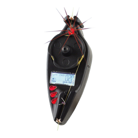
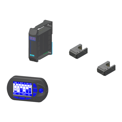
btsr IS3 User manual

Yarn Control System
Operating Manual
60$57#97#+#2#533#.#)#,6611#
(1*/,6+#
%(67#7(&+12/2*,(6#678'<#)#5(6($5&+#


SMART 64 H / 200 K & IS3..
YARN CONTROL SYSTEM
Operating Manual
ENGLISH

Copyright 2001 - BTSR - All rights reserved.
This manual is intended for the users of the SMART 64 H / 200 K. system. It is suggested to carefully read
the instruction reported in this manual before making the connections and use the system.
BTSR reserves the right to change in any time the contents of this manual, without notice.
For any technical or commercial problem, please contact your local BTSR dealer or call directly BTSR
customer service centre. We will be glad to meet your needs.
Thank you for your trust and good job.
The product described herein is compliant with the requirements of 89/336/EEC EMC Directive and
73/23/EEC Low Voltage Directive.
All BTSR products are covered by patents and adopt exclusive, profitable and high tech. Solutions .
Lycra® is a trademark byDuPont

Table of contents
SMART 64 H / 200 K - i -
7$%/(#2)#&217(176
7$%/(#2)#&217(1767$%/(#2)#&217(176
7$%/(#2)#&217(176#
##
#
INTRODUCTION
How to use this Manual............................................................................................................................................. I.1
Symbols used .............................................................................................................................................................. I.2
Chapter 1 - OVERVIEW
System Components...................................................................................................................................................1.1
System’s Operating Principles..................................................................................................................................1.1
Special Features of SMART 64 H / 200 K System...................................................................................................1.1
General Features of SMART BTSR systems...........................................................................................................1.2
Chapter 2 – TECHNICAL DATA AND INSTALLATION
Technical Features.....................................................................................................................................................2.1
Installation..................................................................................................................................................................2.1
Electrical connections ............................................................................................................................................2.1
Example of Generic Application Connection on Small Circular Knitting Machines...........................................2.2
Connecting cables and Power supply devices......................................................................................................2.3
External RESET Connection................................................................................................................................2.4
Chapter 3 – OPERATING
SMART 64 H / 200 K Terminal Features ................................................................................................................3.1
Meaning of Red Leds inside the SMART 64 H / 200 K Terminal’s.......................................................................3.2
IS3.. Sensors Features................................................................................................................................................3.3
Types of IS3.. sensors.................................................................................................................................................3.4
Function of the IS3.. Sensors.....................................................................................................................................3.4
Installation of the IS3.. Sensors.............................................................................................................................3.5
Interpretation of the signalling lights located on the sensors.................................................................................3.5
Settings that affect the sensor detection features.....................................................................................................3.6
Programming examples for F_START/F_STOP and relevant sensor delays .........................................................3.7
Preliminary operations for using the SMART 64 H terminal................................................................................3.8
Operating Sequences..................................................................................................................................................3.9
Activating the Learning Cycle (LEARN)...............................................................................................................3.10
Display Messages during the Control Phase..........................................................................................................3.11
Summary Diagram of SMART 64 H / 200 K Programming/Configuration Menu............................................3.12
P1 Programming Level............................................................................................................................................3.13
SYNC: Proxy / Encoder Pulse Divisor ...............................................................................................................3.13
ZERO: Machine Zero Signal Divisor.................................................................................................................3.14
PHASE: Tolerance on Phase Errors ..................................................................................................................3.14
DEVICES: IS3.. Devices Connected to the System...........................................................................................3.15
Global Automatic Numbering............................................................................................................................3.15
Single Sensor Numbering...................................................................................................................................3.15
Replacing a Sensor.............................................................................................................................................3.16
Adding a New Sensor.........................................................................................................................................3.16
KEY_COD: Password to Access the Programming Menus .............................................................................3.17
K_LEARN: Password to Access the Learning Function..................................................................................3.17
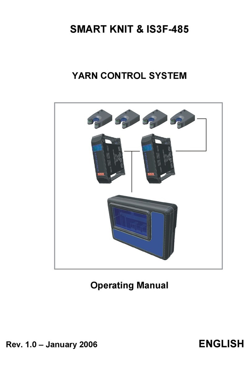
Table of contents
- ii - SMART 64 H / 200 K
P2 Programming Level............................................................................................................................................3.18
BROKE G: Error Tolerance for Broken Yarn (global)....................................................................................3.18
UNCUT G: Error Tolerance for Uncut Yarn (global)......................................................................................3.19
P3 Programming Level............................................................................................................................................3.20
BK D0nn: Error Tolerance for Broken Yarn (on D0nn sensor)......................................................................3.20
UC D0nn: Error Tolerance for Uncut Yarn (on D0nn sensor) ........................................................................3.21
P4 Programming Level............................................................................................................................................3.22
SENS G: Sensitivity (global)................................................................................................................................3.22
DELAY G: Reaction Time (global).....................................................................................................................3.23
P5 Programming Level............................................................................................................................................3.24
SE D0nn: Sensitivity (on D0nn sensor)...............................................................................................................3.24
DE D0nn: Reaction Time (on D0nn sensor).......................................................................................................3.23
TEST Functions........................................................................................................................................................3.26
TEST_SE: Sensors Test.......................................................................................................................................3.26
TEST_CO: Testing the Efficiency Rate over the Communications Line between the
SMART 64 H / 200 K terminal and Sensors......................................................................................................3.27
PX Programming Level...........................................................................................................................................3.28
F_START: START Frequency...........................................................................................................................3.28
F_STOP: STOP Frequency.................................................................................................................................3.29
H_SPEED: Machine Stop Speed.........................................................................................................................3.29
AUTO_C: Auto-Correction.................................................................................................................................3.30
Setting the Production TARGET............................................................................................................................3.31
TARGET settings, with machine stationary......................................................................................................3.31
TARGET and COUNT/REJECT counters reading, with machine running ..................................................3.32
Machine stop when TARGET is reached...........................................................................................................3.32
Reading/Resetting the BROKE and UNCUT Counters........................................................................................3.33
Chapter 4 – TROUBLESHOOTING AND MAINTENANCE
Troubleshooting .........................................................................................................................................................4.1
Temporary Sensor Disabling.....................................................................................................................................4.3
Machine Test ..............................................................................................................................................................4.4
Ordinary Maintenance ..............................................................................................................................................4.4
Repairs........................................................................................................................................................................4.4
Updating the Software Version on SMART Terminals..........................................................................................4.5
Parameters Summary Table .....................................................................................................................................4.6
Appendix A – Quick Reference......................................................................................................................................A.1
Appendix B – Differences between SMART 64 H and SMART 200 K.......................................................................B. 1

Introduction
SMART 64 H / 200 K - I.1 -
,1752'8&7,21
,1752'8&7,21,1752'8&7,21
,1752'8&7,21#
##
#
Congratulations for choosing a BTSR product.
With our SMART 64 H / 200 K yarn control system, you get an innovative, unique
solution, able to offer you multiple advantages concerning quality control of your
production.
SMART 64 H has been designed for application on small circular knitting
machines, while SMART 200 K has been designed for application on medium-
large circular knitting machines.
The system is able to self-learn the yarn sequence picked-up by the knitting
machine during a sample cycle and to indicate any type of error detected during the
subsequent production cycles (broken or missing yarns, uncut or wrong sliding
yarns, wrong threading or wrong picking-up errors, etc.).
This allows to eliminate up to 80% of waste and seconds quality that would
normally occur during production; in addition it dramatically reduce needle
breakages and machine stops, thus allowing a rapid pay-back of your investment.
SMART 64 H / 200 K, combined with IS3.. yarn smart control sensors and
(optionally) with AST pull/extratension devices represents a full and effective
machine control system.
+RZ#WR#XVH#WKLV#0DQXDO#
This Operation Manual is divided into 4 Chapters and 2 Appendices.
Chapter 1 – Overview describes the main features, components and how the
system works.
Chapter 2 – Technical Data and Installation gives the necessary instructions to
install the system correctly.
Chapter 3 – Operation gives a detailed description of the necessary operations to
setup and program the system according to the application needs.
Chapter 4 – Troubleshooting and Maintenance provides a quick guide to solve
the main technical faults of the system.
Appendix A – Quick reference summarises the sequence of operations that staff
who have had sufficient experience in handling the system, have to carry out in
order to setup and program the system.
Appendix B – Differences between SMART 64 H and SMART 200 K summarises
the features and functions that differentiate SMART 200 K from SMART 64 H.

Introduction
- I.2 - SMART 64 H / 200 K
6\PEROV#XVHG#
òHighlights notes, warnings and points to which the attention of the reader
should be directed.
Indicates a particularly sensitive situation which could have an
effect on the safety or proper operation of the system.
IS3.. The IS3.. BTSR sensor family includes a number of variants; these are indicated by
the letters following IS3. The symbol IS3.. generally indicates all the variants of the
IS3 sensor. For further details please refer to paragraph “Types of IS3.. sensors”.
In the operating sequences, this symbol indicates that, to activate the desired
function, you must press and hold for 3 seconds the button.
This symbol, shown on the top of some pages, indicates that the described subject or
feature, refers exclusively to SMART 64 H system and that, for what concerns the
200 K system, you must refer to the Appendix B containing the characteristics that
differentiate SMART 200 K system from SMART 64 H system.
200K →
→→
→A
pp
. B

Overview
SMART 64 H / 200 K - 1.1 -
4#
4#4#
4#0
00
0#29(59,(:
#29(59,(:#29(59,(:
#29(59,(:#
##
#
6\VWHP#&RPSRQHQWV#
The SMART 64 H / 200 K system includes a control/programming terminal and a
variable number of IS3.. type sensors connected to the terminal using a single
multi-port interface cable. Optionally, it is possible to connect AST devices
providing a self-compensation of yarn pulls or extratension, without stopping the
machine.
6\VWHP·V#2SHUDWLQJ#3ULQFLSOHV#
The sensors’ detection features (Start Frequency →F_START, Stop Frequency →
F_STOP, Sensitivity →SENS, Reaction Time →DELAY)can be programmed
according to the type of yarn being processed.
These features must be programmed on each sensor and can be changed according
to the article which is being processed.
The terminal has in fact the function of programming and, as conditions change, it
can vary the sensors’ features, according to the production requirements.
The main task of SMART 64 H / 200 K is to provide a continuous production
monitoring (CONTROL function), by comparing each production cycle (LEARN
function) under “ideal” conditions, thus detecting possible deviations with respect
to the above mentioned sample cycle and stopping the knitting machine when the
detected errors exceed the set tolerance.
The system also allows you to set the number of stockings/body blanks to be
produced within a given working session (TARGET function), stopping the knitting
machine when such number is reached.
6SHFLDO#)HDWXUHV#RI#60$57#97#+#2#533#.#6\VWHP#
The SMART 64 H / 200 K system has a set of unique features which make it a
true microcomputer dedicated to programming/control of production and statistical
analysis of technical faults.
During the production monitoring phase the system stores all the technical faults
each sensor founds, allowing the machine operator to analyse which and how many
technical faults have been detected by each individual sensor.
The main advantages of this solution can be summarised as follows:
ƒ#Absolute flexibility:
thanks to the possibility to quickly change the sensors’ program, according to
the article to be processed.
ƒ#Maximum simplicity:
concerning the installation as well as programming and administration of the
system.
ƒ#Maximum precision:
the possibility of programming the technical features of sensors according to the
type of yarn to be processed, guarantees a perfect symbiosis between sensor and
yarn.

Overview
- 1.2 - SMART 64 H / 200 K
*HQHUDO#)HDWXUHV#RI#60$57#%765#V\VWHPV#
ƒ#Self Learning Technique (BTSR Patents)
The system automatically learns the sequence of yarns used by the textile
machine.
ƒ#IS3.. Sensors (Image Smart Scanning Sensor) (BTSR Patents)
The sensors of the IS3.. series are connected to the SMART control terminal by
means of a simple multi-connector cable, thus making quite easy the system
installation task.
ƒ#Automatically assigned numbers (BTSR Patents)
The identification of sensors is performed by the system by means of an
automatic numbering procedure resulting in a simple and fast system
configuration.
ƒ#Programmable Functions
The systems allows programming either in global or selective way the sensor
detection features (Sensor Image Variation Frequency, Sensitivity, Reaction
Time, Tolerance, etc.).
ƒ#Multisensor System
The system allows the connection of all types of sensors from the IS3.. series,
which check that the yarn runs properly; and there is the possibility to combine
sensors of the new generation (equipped with a “Touch Light” device) with
sensors equipped with the “PUSH” membrane button.
ƒ#Production Data
The system records, during production, the machine stops stored by each sensor
and by error type.
ƒ#Easy Monitoring
Besides the information provided on the graphical display of the SMART 64 H
/ 200 K terminal, each IS3.. series sensor has a red LED that, when flashing,
indicates the location of the technical fault of the yarn, making intervention for
the operator easier.
ƒ#Sensor Diagnostic
Each IS3.. sensor signals the operational status by means of two LEDs.
(For further information please refer to “Interpretation of the signalling lights
located in the sensors").

Technical Data and installation
SMART 64 H / 200 K - 2.1 -
5#
5#5#
5#²
²²
²#7(&+1,&$/#'$7$#$1'#,167$//$7,21
#7(&+1,&$/#'$7$#$1'#,167$//$7,21#7(&+1,&$/#'$7$#$1'#,167$//$7,21
#7(&+1,&$/#'$7$#$1'#,167$//$7,21#
##
#
7HFKQLFDO#)HDWXUHV#
60$57#97#+#2#533#.#7HUPLQDO#
Power supply voltage 15 Vac or 24 Vdc ± 10%
Maximum Absorption 100 mA
Dimensions 135 x 95 x 40 mm
Temperature range 0° - 60 °C
LCD Graphical Display 80 x 40 mm
Integrated Touchpad 5 membrane buttons with integrated red LED
Protection 2 fuses 5 x 20 – 1A
,6611#6HQVRUV
#
Power supply voltage 12 .. 24 Vdc ± 20%
Absorption Typical 12.5 mA (max 20 mA*)
Reaction Delay Programmable from 5 to 1000 msec
Sensitivity Programmable (10 levels)
Signalling With integrated LEDs
Dimensions 15 x 15 x 36,5 (narrow) - 25 x 15 x 36,5 (wide)
Temperature range 0° - 60 °C
,QVWDOODWLRQ#
The installation of the SMART 64 H / 200 K system depends on the type of
application to which it is destined and on the number of sensors to be connected to
it. When there are less than 32 sensors, it is possible to connect them directly to the
SMART terminal, otherwise it is necessary to use a stabilised power supply PSU
10A. This is capable of supplying up to 8 independent backbone lines to which it is
possible to connect the same amount of sensor chains (up to a maximum of 64 for
SMART 64 H and 200 for SMART 200 K).
(OHFWULFDO#FRQQHFWLRQV#
* Model with “PUSH”
button

Technical Data and installation
- 2.2 - SMART 64 H / 200 K
([DPSOH#RI#*HQHULF#$SSOLFDWLRQ#&RQQHFWLRQ#RQ#6PDOO#&LUFXODU#.QLWWLQJ#0DFKLQHV#
Concerning all electrical systems, it is a suggested rule to ensure that the ground cable
(GND)
is connected to the sensor support.
200K →
→→
→A
pp
. B

Technical Data and installation
SMART 64 H / 200 K - 2.3 -
&RQQHFWLQJ#FDEOHV#DQG#3RZHU#VXSSO\#GHYLFHV#
To correctly install the SMART 64 H system and sensors, it is necessary to use a
certain number of connecting cables provided by BTSR; their length and type
depend on the specific requirements and application types.
The following table lists at glance the types and lengths of the main connecting
cables, which BTSR may provide. For further details and queries about the cables
and options available, please contact your local dealer.
60$57#3RZHU#FDEOHV#+,22#&RQQHFWRU,#
FE10/200 Length 200 cm
FE10/500 Length 500 cm
KITSMART-H Length 200 cm or 500 cm
0XOWL0FRQQHFWRU#&DEOHV#IRU#&RQQHFWLQJ#,6611#6HQVRUV#
MA10/12CR Ready for 12 sensors with pitch of 10 cm
MA10/16CR Ready for 16 sensors with pitch of 10 cm
MA10/24CR Ready for 24 sensors with pitch of 10 cm
MA10/32CR Ready for 32 sensors with pitch of 10 cm
MA15/8CR Ready for 8 sensors with pitch of 15 cm
MA15/12CR Ready for 12 sensors with pitch of 15 cm
MA15/16CR Ready for 16 sensors with pitch of 15 cm
MA15/24CR Ready for 24 sensors with pitch of 15 cm
&RQQHFWLQJ#FDEOHV#IRU#6LQJOH#6HQVRU#ZLWK#$03#0DOH#&RQQHFWRU#
MA50/CR Length 50 cm
MA100/CR Length 100 cm
MA150/CR Length 150 cm
&DEOHV#7#[#3/68#PP#ZLWK#)HPDOH#WR#)HPDOH#&RQQHFWRU#IRU#
FRQQHFWLRQV#EHWZHHQ#60$57#97#+#DQG#0$43211&5#0XOWL0FRQQHFWRU#
FDEOH#
FE100/FEC Length 100 cm
FE200/FEC Length 200 cm
FE300/FEC Length 300 cm
FE400/FEC Length 400 cm
200K →
→→
→A
pp
. B

Technical Data and installation
- 2.4 - SMART 64 H / 200 K
50ZD\#&DEOH#IURP#RQH#0DOH#WR#7ZR#)HPDOH#
MA2FE
70ZD\#&DEOH#IURP#RQH#0DOH#WR#)RXU#)HPDOH#
MA4FE
7UDQVIRUPHUV#IRU##60$57#97#+#
TRF1524/100VA Output 15/24 Vac 100VA (can be used with up to 32 sensors)
TRF24/300VA Output 24 Vac/300VA (can be used with more than 32 sensors)
(PSU10A)
6WDELOLVHG#3RZHU#6XSSO\#ZLWK#57#9GF#RXWSXW/#43$#3HDN/#9$#
FRQWLQXRXV#
PSU 10A Required with more than 32 sensors
([WHUQDO#5(6(7#&RQQHFWLRQ#
The external RESET signal is used to reset the system in case of error, in the place
of terminal’s RESET button.
RESET WITH PUSH BUTTON: In this case the RESET input is provided by a
contact which connects to ground when the
terminal is to be reset.
AUTOMATIC RESET: In this case the RESET input is directly
(not for 200 K)connected to ground. When the system detects
a failure, it activates the STOP signal and
indicates the failure occurred on display. As
soon as the machine stops, SMART 64 H
releases the STOP output, but keeps the
display message, until it receives five
synchronism pulses (PRX), generated by the
machine restart phase.
200K →
→→
→A
pp
. B

Operating
SMART 64 H / 200 K - 3.1 -
6#
6#6#
6#²
²²
²#23(5$7,1*
#23(5$7,1*#23(5$7,1*
#23(5$7,1*#
##
#
60$57#97#+#2#533#.#7HUPLQDO#)HDWXUHV#
As in all SMART BTSR systems,the operation of SMART 64 H / 200 K system
is controlled by just 5 membrane buttons and it is monitored by a LCD graphic
display, which guides the operator through all programming and administration
phases of the system, by means of straight-forward messages which can be
understood clearly and immediately.
On the top left side of each button there is a red LED, which indicates particular
conditions.
The display screen includes two separate zones used respectively for displaying
messages to the operator $during the system programming and administration
phases and for signalling the operating status and levels in which the system is
working %.
The following picture shows the location of the buttons and display zones that
constitute the control panel of the system.
41# (17(5#EXWWRQ#
Pressing and holding for 3 seconds the ENTER button when the system is in
control condition (CONTROL nnnnn displayed), gives access to P1 programming
level.
Pressing and holding for 3 seconds the ENTER button while the system is at
beginning of P1 menu (**P1** displayed), gives access to PX programming level.
When the system is running any of the programming menus, pressing the ENTER
button confirms the current parameter and selects the next parameter within the
current menu. When pressed on the last item of the menu, causes the return to the
beginning of the same menu (cyclic function).
51# 5(6(7#EXWWRQ#
When the system is running any of the programming menus, pressing the RESET
button causes the return to the beginning of the same menu; pressing it again
causes the return to control condition (CONTROL nnnnn displayed).

Operating
- 3.2 - SMART 64 H / 200 K
61# 1(;7#&<#EXWWRQ#
During the parameters setting phase, within a programming menu, it allows you to
increase the numeric value of current filed. If it is kept continuously pressed, the
numeric field increases more quickly.
When the system is in control condition (CONTROL nnnnn displayed and red Led
on, inside the CONTROL button), pressing the NEXT CY button activates the
NEXT CYCLE function:
- The system is disabled for a complete control cycle
- The red Led inside CONTROL button turns OFF
- The red Led inside NEXT CY button turns ON.
When SMART 64 H / 200 K receives the STOCKING/BODY BLANK ZERO
signal (ZPX), the system automatically returns to control condition (CONTROL
Led on, NEXT CY Led off).
When alphanumeric data are entered (for instance the Key_cod or K_learn), this
button allows the increase of characters pointed by the cursor, according to the
following cyclic sequence:
71# &21752/#EXWWRQ#
During the programming phases requiring the entry of 2 or more parameters within
the same screen shot, pressing the CONTROL button switches from the current
parameter (indicated by blinking cursor), to the next parameter (cyclic function).
81# 5(3($7#EXWWRQ#
During the parameters setting phase, within a programming menu, it allows you to
decrease the numeric value of current field. If it is kept continuously pressed, the
numeric field decreases more quickly.
When alphanumeric data are entered (for instance the Key_cod or K_learn), this
button allows the decrease of characters pointed by the cursor, according to the
following cyclic sequence:
0HDQLQJ#RI#5HG#/HGV#LQVLGH#WKH#60$57#97#+#2#533#.#7HUPLQDO#
During normal operation, the SMART 64 H / 200 K terminal signals the current
working condition through the status of Leds embedded in the five function
buttons. The meaning of Leds is the following:
ENTER LED If switches on and off alternatively, each time the system
receives a synchronism signal (PRX).
RESET LED It switches on when the LEARN function is activated.
NEXT CYCLE LED It switches on when the NEXT CYCLE function is activated
(next cycle).
CONTROL LED It switches on when the system is in Control phase.
REPEAT LED It switches on when the STOCKING/LENGTH MATERIAL
ZERO signal (ZPX) is active, i.e. when the machine is in zero
condition.

Operating
SMART 64 H / 200 K - 3.3 -
91# 2SHUDWRU·V#PHVVDJH#$UHD=#
The menu choices, or settings for the selected function during programming or
setup phase of the system as well as service messages are displayed here with large
size fonts (1,5 x 0,8 cm), easy to read even from a distance, when the system is
running normally. In other words, this area shows all the necessary information to
guide the operator step by step through the programming phase and interactive
management of the system.
The presence of a flashing cursor (---) indicates the position where the operator
can enter a numeric value or variable setting which will replace the value currently
displayed.
:1# 2SHUDWLQJ#6WDWXV#6LJQDOOLQJ#$UHD#
To enable a more direct and evident interpretation of the operating context in
which you are working, on the right hand side and bottom side of the operator
message area, 16 rectangular boxes (labels) are implemented. They display the
operating status of the system, and the hierarchic level of the menu at which you
are operating.
More specifically, the PROGRAM label indicates that you are operating in one of
the following modes: configuration, programming or data transmission to the
sensors. The CONTROL label indicates that the system is operating normally with
all monitor functions enabled, and according to the settings currently set in the
system. In this phase the message display indicates CONTROL nnnnn. The
ERROR label indicates that an error has been detected during normal operation of
the system. In this case the message display shows the type of error detected (for
further information please refer to Operating Sequences).
The labels P1 .. P5 indicate the hierarchic level of the menu in which you are
operating.
The WAIT label indicates that the button you are pressing has a timed function, for
instance if you press ENTER while the system is in Control condition, the WAIT
label indicates that, if you keep the button pressed for 3 seconds you will access the
P1 menu.
,6611#6HQVRUV#)HDWXUHV#
The IS3.. electronic sensors are capable of detecting, thanks to a patented and
advanced control technology, the image variation of a moving yarn under control;
it can show with absolute certainty the actual movement or stop condition of the
yarn. The technique based on image variation makes the IS3.. sensor exempt from
the influence of environment/yarn conditions: i.e. humidity, conductivity and
machine vibrations. It does not require any physical contact with the yarn under
control and therefore allows perfect monitoring without affecting the tension
features of the yarn itself in any way. The IS3.. devices are the most reliable and
advanced solution for yarn control in textile machines. IS3.. is an unique electronic
sensor for yarn control; when combined with the SMART series controllers, thanks
to a patented innovating technique (Image Smart Scanning Sensor), it does not
require complex cabling and long installation time; the new multi-connector cable
allows in fact to control multiple sensors. IS3.. is full programmable for an easy
fitting to the control of any type of yarn/application.
SMART
64 H

Operating
- 3.4 - SMART 64 H / 200 K
7\SHV#RI#,6611#VHQVRUV#
The IS3.. Sensors are available in different typology to satisfy the specific
requirements of each installation/application. The following diagram shows in
detail the codes for the various models of sensors depending on possible variations.
Example: IS3NHS means: New generation high sensitivity narrow sensor.
)XQFWLRQ#RI#WKH#,6611#6HQVRUV#
The IS3.. sensors of the new generation have two signalling lights (upper green
LED, lower red LED) and a “Touch Light” button.
During the automatic numbering of the sensors (flashing green LED) it assigns the
displayed number (shown in the devices configuration screen) to the sensor.
The IS3.. Sensors of the previous generation (perfectly compatible with those of the
new generation) also have the two signalling lights (upper green LED, lower red
LED) and a membrane mechanical button located on the side of the sensor.
Touch Light

Operating
SMART 64 H / 200 K - 3.5 -
,QVWDOODWLRQ#RI#WKH#,6611#6HQVRUV#
The installation of IS3.. Sensors is an extremely simple operation as there is only
one multi-connector cable, which allows the chained interconnection of all sensors,
and their connection to the control terminal SMART 64 H / 200 K or to the power
supply PSU 10A. To install the sensors operate as follows:
áPrepare the adequate multi-connector cable.
Open the rear cover of the sensor.
!Plug the male connector of the cable into the female connector of the sensor
(the reference key on the male connector must be positioned on the upper side
of the connector).
"Close the rear cover and secure the sensor using a M3 screw.
#Check that the yarn rooms in the centre of the area üshown in the following
pictures.
,QWHUSUHWDWLRQ#RI#WKH#VLJQDOOLQJ#OLJKWV#ORFDWHG#RQ#WKH#VHQVRUV#
Green LED ON Normal operation, the yarn is running inside the sensor;
No technical fault detected by the sensor.
Red LED ON Yarn stopped.
Green LED FLASHING The system is in automatic numbering phase.
Red LED FLASHING During machine operation the sensor has detected a
fault.
(BROKEN: broken yarn - UNCUT: uncutted yarn).
Green LED ON
Red LED ON Stopped sensor. Switch off, then switch on the system.
If the condition is permanent, replace the sensor.
Green LED FLASHING
Red LED FLASHING Indicates a technical fault in the sensor
(e.g. a loss of
stored data).
Try to reprogram the sensor. If the fault
remains, replace the sensor.

Operating
- 3.6 - SMART 64 H / 200 K
6HWWLQJV#WKDW#DIIHFW#WKH#VHQVRU#GHWHFWLRQ#IHDWXUHV#
The IS3.. series sensors are not simply detecting the presence of the yarn, but they
are working as true micro-computers. They provide a digital signal output, which
reflects the condition of the yarn within the detection area:
ƒ#Normal yarn running condition
ƒ#Yarn stopped or broken condition
The functioning of the sensor is based on the principle of variation of the image
relative to the shape of the yarn, detected by the tiny “camera”, which is
implemented inside the sensor. Such a variation of image normally occurs only if
the yarn is in actual movement inside the detection area, i.e. only if the yarn is
running.
Nevertheless, in certain cases, there may be some variation of image even though
the yarn is not running normally, this is the case of a broken yarn oscillating inside
the detection area.
Finally there are other factors that can affect the detection activity of the sensors,
like the size and type of yarn (silk, wool, acrylic, Lycra®, single filament nylon), as
the variation of the image depends on these factors as well.
That’s why the microcomputer embedded in the sensor, processes the images
provided by the “camera” by means of the sensor memory, which takes into
account also these other influencing factors.
The variables of this program are represented by the settings connected to the
article, which is being worked, i.e.
ƒ#Start Frequency (F_START)
ƒ#Stop Frequency (F_STOP)
ƒ#Sensitivity (SENS)
ƒ#Reaction Time (DELAY)
6WDUW#)UHTXHQF\#
+)B67$57,
#
This setting indicates the minimum frequency of image variation, beyond which
the sensor signals that the yarn runs normally (green LED ON).
It can be programmed to a value between 1and 10.
6WRS#)UHTXHQF\
+)B6723,
#
This setting indicates the minimum frequency of image variation, below which the
sensor signals that the yarn runs normally (red LED ON).
It can be programmed to a value between 1and 10.
Other manuals for IS3
1
This manual suits for next models
2
Table of contents
Other btsr Control System manuals

btsr
btsr SMART 200 TTS User manual

btsr
btsr SMART 3000TW User manual

btsr
btsr SMART KTF 2000 User manual

btsr
btsr WINDINGFEEDER User manual

btsr
btsr MATRIX CUBE User manual

btsr
btsr SMART MATRIX TWIST User manual

btsr
btsr ULTRAFEEDER User manual

btsr
btsr SMART 200 MTC User manual

btsr
btsr SMART MATRIX WINDINGFEEDER User manual

btsr
btsr SMART MATRIX QUILT User manual