manuals.online logo
Brands
  1. Home
  2. •
  3. Brands
  4. •
  5. COZY
  6. •
  7. Gas Heater
  8. •
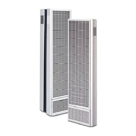
  9. COZY WOW254 and User manual

COZY WOW254 and User manual

This manual suits for next models

3

Other COZY Gas Heater manuals

COZY VC501A and User manual

COZY

COZY VC501A and User manual

COZY BBT103 and User manual

COZY

COZY BBT103 and User manual

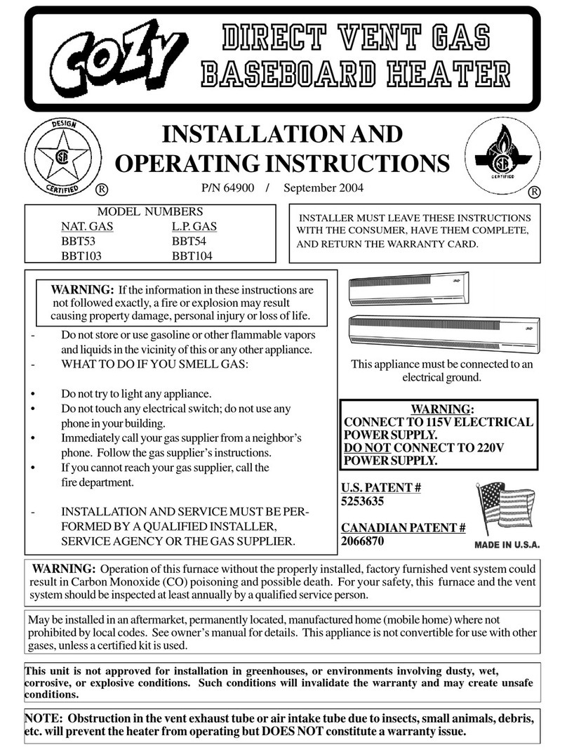
COZY BBT54 and User manual

COZY

COZY BBT54 and User manual

COZY BBT53 and User manual

COZY

COZY BBT53 and User manual

COZY WOW253 and User manual

COZY

COZY WOW253 and User manual

COZY VCR501A-H and User manual

COZY

COZY VCR501A-H and User manual

COZY VFT201 and User manual

COZY

COZY VFT201 and User manual

COZY VC201A-H and User manual

COZY

COZY VC201A-H and User manual

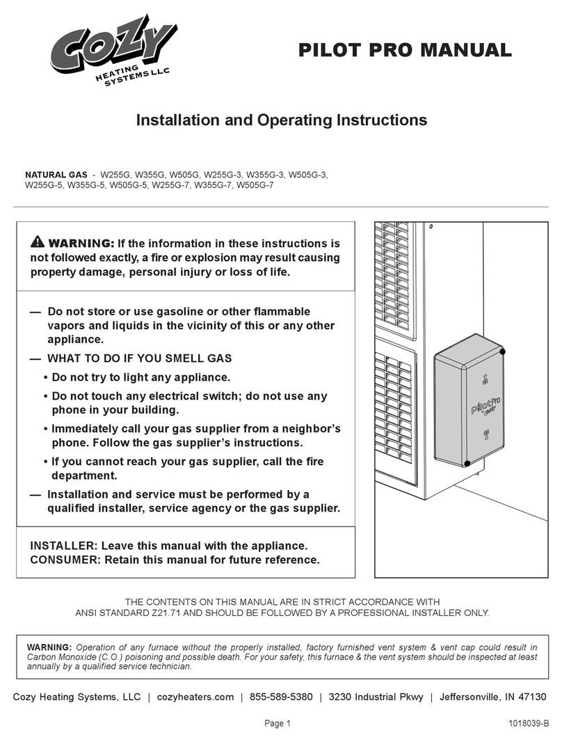
COZY PILOT PRO Series User manual

COZY

COZY PILOT PRO Series User manual

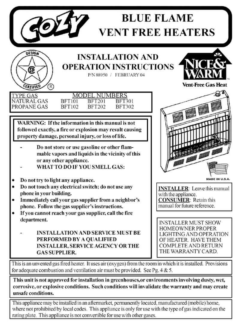
COZY BFT101 and User manual

COZY

COZY BFT101 and User manual

COZY BFT101 and User manual

COZY

COZY BFT101 and User manual

COZY BBT53 and User manual

COZY

COZY BBT53 and User manual

COZY WOW253 and User manual

COZY

COZY WOW253 and User manual

Popular Gas Heater manuals by other brands

Desa ROPANE CONSTRUCTION HEATERS owner's manual

Desa

Desa ROPANE CONSTRUCTION HEATERS owner's manual

Desa BCLP375 owner's manual

Desa

Desa BCLP375 owner's manual

Robur Line F1 Series User, installation and service manual

Robur

Robur Line F1 Series User, installation and service manual

Superior BGE18NV Installation and operation instructions

Superior

Superior BGE18NV Installation and operation instructions

Dru Room-sealed atmospheric gas-fired heating... user manual

Dru

Dru Room-sealed atmospheric gas-fired heating... user manual

klover TKR 35 user guide

klover

klover TKR 35 user guide

Rothenberger Industrial 035984 instruction manual

Rothenberger Industrial

Rothenberger Industrial 035984 instruction manual

Hargrove Timberland Glow Operation and installation guide

Hargrove

Hargrove Timberland Glow Operation and installation guide

Kinder Cameo BF Installation and maintenance instructions

Kinder

Kinder Cameo BF Installation and maintenance instructions

Qlima GH 438 B-2 Directions for use

Qlima

Qlima GH 438 B-2 Directions for use

Desa 125-R owner's manual

Desa

Desa 125-R owner's manual

Gasmate AH100 Series instructions

Gasmate

Gasmate AH100 Series instructions

Brant Radiant Heaters QTD Series User instruction

Brant Radiant Heaters

Brant Radiant Heaters QTD Series User instruction

Medallion MBP20TLB OWNER'S OPERATION AND INSTALLATION MANUAL

Medallion

Medallion MBP20TLB OWNER'S OPERATION AND INSTALLATION MANUAL

Sealey LP35.V5 instructions

Sealey

Sealey LP35.V5 instructions

Italkero Falo Evo User manual and assembly instructions

Italkero

Italkero Falo Evo User manual and assembly instructions

Desa 30LP owner's manual

Desa

Desa 30LP owner's manual

Williams 2509822A owner's manual

Williams

Williams 2509822A owner's manual

manuals.online logo
manuals.online logoBrands
  • About & Mission
  • Contact us
  • Privacy Policy
  • Terms and Conditions

Copyright 2025 Manuals.Online. All Rights Reserved.

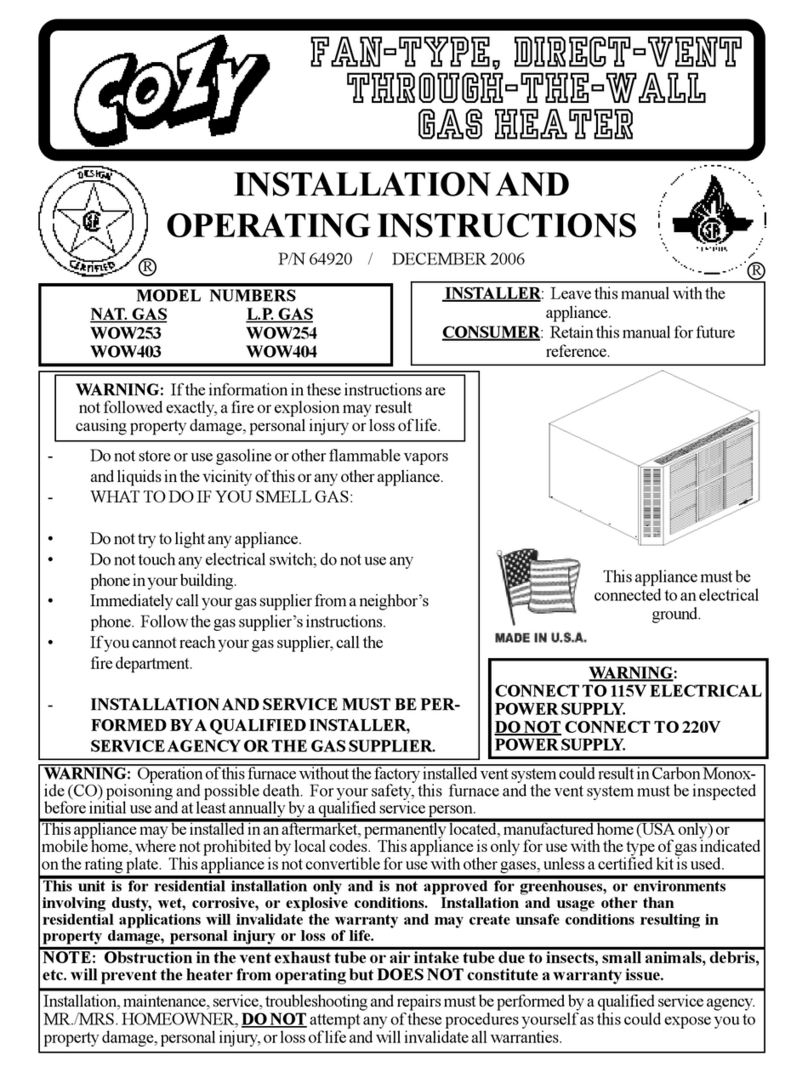
!INSTALLATION AND
OPERATING INSTRUCTIONS
P/N 64920 DECEMBER 2006
MODEL NUMBERS
NAT. GAS L.P. GAS
WOW253 WOW254
WOW403 WOW404
(
I IJll_ 7
-m-,""
INSTALLER: Leave this manual with the
appliance.
CONSUMER: Retain this manual for future
reference.
WARNING: If the information in these instructions are
not followed exactly, a fire or explosion may result
causing property damage, personal injury or loss of life.
Do not store or use gasoline or other flammable vapors
and liquids in the vicinity of this or any other appliance.
WHAT TO DO IF YOU SMELL GAS:
Do not try to light any appliance.
Do not touch any electrical switch; do not use any
phone in your building.
llnlnediately call your gas supplier from a neighbor's
phone. Follow the gas supplier's instructions.
If you cannot reach your gas supplier, call the
fire department.
INSTALLATION AND SERVICE MUST BE PER-
FORMED BY A QUALIFIED INSTALLER,
SERVICE AGENCY OR THE GAS SUPPLIER.
i•i
N_DE JN UoS&,
This appliance must be
connected to an electrical
ground.
WARNING:
CONNECT TO l15V ELECTRICAL
POWER SUPPLY.
DO NOT CONNECT TO 220V
POWER SUPPLY.
WARNING: Operation of this furnace without the factory installed vent system could result in Carbon Monox-
ide (CO) poisoning and possible death. For your safety, this furnace and the vent system must be inspected
before initial use and at least annually by aqualified service person.
This appliance may be installed in an aflennarket, permanently located, lnanul_acturedhome (USA only) or
mobile home, where not prohibited by local codes. This appliance is only for use with the type of gas indicated
on the rating plate. This appliance is not convertible for use with other gases, unless a certified kit is used.
This unit is for residential installation only and is not approved for greenhouses, or environments
involving dusty, wet, corrosive, or explosive conditions. Installation and usage other than
residential applications will invalidate the warran D" and may create unsafe conditions resulting in
proper D"damage, personal injury or loss of life.
NOTE: Obstruction in the vent exhaust tube or air intake tube due to insects, small animals, debris,
etc. will prevent the heater from operating but DOES NOT constitute a warranty issue.
Installation, maintenance, service, troubleshooting and repairs must be performed by a qualified service agency.
MR./MRS. HOMEOWNER, DO NOT attempt any of these procedures yourself as this could expose you to
property damage, personal injury, or loss of life and will invalidate all warranties.
The State of Massachusetts requires that installation and service of a gas
appliance be performed by a plumber or gas fitter licensed in the
Commonwealth of Massachusetts.
For bedroom window installation, the State of Massachusetts requires two or more operable
windows in the bedroom that are in compliance with 780CMR, Massachusetts Building Code.
CONTENTS
Introduction ...................................... 2
Specifications and Dimensions ................. 2
Safety Rules ................................... 3
Location ................................................... 5
Clearances ..................................... 6
Installation ..................................... 5 - 11
Lighting Instructions ........................... 12
Proper Burner Flame ................................. 13
Burner Orifice ........................................... 13
Gas Conversion ......................................... 14
Wiring Diagram ................................. 15
Sequence of Operation ............................... 16
Maintenance Instructions ............................. 17
Removing Main Burner. ............................. 18 - 19
Removing Colnbustion Tube Assembly. ...... 20 - 21
Trouble Shooting ............................. 22 - 23
Parts Drawing ................................. 25 - 26
Parts List ....................................... 25 - 28
Warranty ......................................... 29
INTRODUCTION
THIS IS A GAS-FIRED, DRAFT INDUCED, POWER DEPENDENT, DIRECT VENT WALL FURNACE;
THAT WILL OPERATE SAFELY AND PROVIDE AN EFFICIENT SOURCE OF HEAT WHEN
INSTALLED, OPERATED AND MAINTAINED AS RECOMMENDED IN THESE INSTALLATION AND
OPERATING INSTRUCTIONS, LOCAL CODES AND THE LATEST EDITION OF ANSI Z223.1/NFPA54
OR 1NCANADACSAB149.1. READ THESE INSTRUCTIONS THOROUGHLY BEFORE 1NSTALL1NC_
SERVICING, OR USING THE APPLIANCE. IFYOU DO NOT UNDERSTAND ANY PART OF THESE
INSTRUCTIONS CONSULT LOCAL AUTHORITIES, OTHER QUALIFIED INSTALLERS, SERVICE
AGENCIES, THE GAS SUPPLIER OR THE MANUFACTURER.
SPECIFICATIONS AND DIMENSIONS
Your Direct Vent Wall Furnace is shipped complete in one carton. This carton contains the furnace, installation
and operating instructions, ball-valve w/flex connector, wall thermostat, 20' wire, insulated staples, window
enclosure panels, caulking, weather stripping, and support brackets.
MODEL
NO.
WOW253
WOW254
WOW403
WOW404
INPUT
BTU/HR.
20,000 BTU
20,000 BTU
40,000 BTU
40,000 BTU
CABINET GAS T_E
WIDTH DEPTH HEIGHT CONN. GAS
14-3/8" 28-3/16" 17-1/8" 3/8" NAT.
3651ran 7161ran 4351ran
14-3/8" 28-3/16" 17-1/8" 3/8" L.P
3651ran 7161ran 4351rnn
25" 22" 17-1/8" 3/8" NAT.
6351ran 5591ran 4351rnn
25" 22" 17-1/8" 3/8" L.P
6351ran 5591ran 4351ran
MAX. WALL
Thickness
18"
458 mln
18"
458 mm
18"
458 mm
18"
458 mln
MIN. _VALL
Thickness
4 _
102mln
4"
102mm
4"
102mm
4"
102mln
Page 2
SAFETY RULES
The Direct Vent Gas Wall/Window Heater and its components meet all applicable safety standards when installed as
directed in this manual. For sate installation and operation of your Direct Vent Gas Wall/Window Heater, read all
these instructions before you begin. Failure to follow them exactly will void your warranty and may result in fire,
property damage, personal iniury, and loss of life.
,
2.
3.
,
5.
6.
7.
.
9.
10.
11.
12.
13.
14.
15.
16.
17.
18.
19.
20.
21.
22.
23.
24.
25.
26.
Improper installation, adjustment, alteration, service, or maintenance can cause property damage, bodily
injury, or death.
Use in residential application only, non residential installation will void the warranty, and may result in property
damage, personal iniury and loss of life.
The installation must conform with local codes or in the absence of local codes with the National Fuel Gas
Code, ANSI Z223.1/NFPA54, Natural Gas and Propane Installation Code, CSA B 149.1. A copy may be
obtained from the CSA International, or the National Fire ProtectionAssociation, Batterymarch Park, Quincy,
MA. 02269. In Canada, use latest edition of CAN1-B 149 installation code.
DO NOT INSTALL THIS FURNACE IN A RECREATIONAL VEHICLE.
Do not operate this heater unless the thctory installed vent system is in place.
Check the rating label to be sure heater is equipped for the type gas you intend to use.
Never use a match, candle, flame or other source of ignition to check for gas leaks. Use only soapy water,
liquid detergent, or an approved gas leak solution.
Your heater, including vent system must be inspected at least annually by a qualified service technician.
Before cleaning or servicing, turn off the gas and allow heater to cool.
Do not operate heater without all components properly installed.
Due to high temperatures, the heater should be located out of traffic and away from furniture and drapes.
Children and adults should be alerted to the hazard of high surface temperature and should be kept away
to avoid burns or clothing ignition.
Young children should be carefully supervised when they are in the same room with the heater.
Do not place clothing or other flammable material on or near the heater.
INSTALLATION AND REPAIR MUST BE DONE BY A QUALIFIED SERVICE PERSON. THE
HEATER MUST BE INSPECTED BEFORE USE AND AT LEAST ANNUALLY BYA PROFESSIONAL
SERVICE PERSON. More frequent cleaning may be required due to excessive lint from carpeting, bedding
material, etc. It is imperative that control compartments, burner, and circulating air passageways of the
heater be kept clean.
Do not install in a closet, alcove, or small hallway where the heater could be isolated from the space to
be heated by closing a door.
Do not place anything around the heater or vent that will obstruct the flow of combustion and
ventilation air. Special note must be taken outside the home in regard to shrubs, flowers, trees, etc., including
snow build-up on top of these items that could block the air intake or vent exhaust tubes.
The appliance, when installed, must be electrically grounded in accordance with local codes or, in the
absence of local codes, with the latest edition of National Electrical Code, ANSI/NFPA 70. In Canada, use
CSA C22.1.
Never operate this heater without the burner sight glass in place or with the glass broken or missing.
If it is suspected that rising water may enter the heater, turn off the gas immediately.
Do not use the heater if any part has been under water. Immediately call a qualified service technician
to inspect and clean the appliance and to replace any part of the control system and any gas control which
has been under water.
Damaged gaskets or sealing material within the vent or air intake system must be replaced prior to operating
the heater. Failure to do so may result in property damage, personal iniury, loss of life or unsatisfactory
performance.
The front panel, if removed for servicing, must be replaced prior to operating heater.
This heater must NOT be connected to a chimney flue.
The appliance area must be kept clear and tree from combustible materials, gasoline, and other flammable
vapors and liquids.
This appliance is equipped with a three-prong (grounding) plug for your protection against shock hazard and
should be plugged directly into a properly grounded three-prong receptacle. Do not cut or remove the
grounding prong from this plug.
Page 3
WARNING:
STEP 1.
a)
b)
c)
INSTALLATION
Failure to follow these instructions exactly may result in poor perfonnance, property_ damage,
personal injury, or loss of life. Installation must be done by a qualified service person.
PREPARING TO INSTALL HEATER
Open carton and caret'ully remove heater and all additional parts.
Make sure all components illustrated in Figure 1have been shipped. You should have
received:
1 - Wind-O-Warm Window/Wall Direct Vent Gas Heater
1 - Ball Valve with Flex Connector
2 - Support Brackets
2 - Side Panels
1 - Packing set including (Caulking, Thermostat, Thermostat Wire, Insulated Staples,
Weather Stripping, and Installation and Operating Instructions)
Check rating plate on heater to verity correct model number and type of gas for intended use.
....•.....................................o...... HEATER
%%,,
.........FRONTPANEL
/
............. SI_STALLATION
INSTRUCTIONS
WINDOW
TRIM (2)
SUPPORT
BRACKET(2) .................
FLEX GAS LINE
, WITH SHLFFOFF
WEATHER STRIPPING
.......... THERMOSTAT WIRE
.... ...........................THERMOSTAT
STAPLES (10)
..... CAULKING
FIGURE 1
LOCATION
STEP 2
1. This heater must be installed through an opening on an outside wall. The heater may be installed in an
existing window or opening cut through a wooden, brick, or masonl T wall.
2. For most efficient performance, locate heater as centrally as possible in the area to be heated.
3. Once a desired location is selected, and before cutting hole, check the outside of the structure for required
clearances to vent exhaust and air intake. See Figure 2. (Cont'd. on next page... )
Page 4
FIGURE 2. VENT TERMINAL CLEARANCES
VENT TERMINAL
AIR SUPPLY INLET
AREA WHERE TERMINAL
IS NOT PERMITTED
0_
A Clearance above grade, veranda, porch, deck. or balcony
B Clearance to _indm_ or door that may be opened
C Clearance to permanently closed windm_
D Vertical clearance to ventilated soffit located
Canadian Installations 1
12 Inches (30 cm)
6 Inches (15 cm) lPr appliances < I0,000 Btuh (3 k_Q, 12 inches (30 cm)
lbr appliances > 10,000 Btuh (3 kx_) and< 100,000 Btuh (30 kxx), 36
inches (91 cm) lor appliances > I00,000 Btuh (30 k_Q
* 12 Inches (30 cm) recommended to prevent condensation on windm_
U.S. Installations 2
12 Inches (30 cm)
6 Inches (15 cm) lbr appliances< I0,000 Btuh (
for appliances > 10.000 Btuh (3 k'_l and < 50.00
inches (30 cm) tor appliances > 50,000 Btuh (I5
* 12 Inches (30 cm) recommended to prevent cot
In accordance with the current CSA B t 49.1. Natural (;_s and Propane blstallatio, (.od_,.
2 lnaccordance\viththecurrentANSlZ223.1/NFPA54, NationalF_elGa_Code.
+ A vent shall not terminate directly above a sidewalk or paved driveway that is located bclween two single lamily d\_ellings and sc_'vesboth dwellings.
:i: Permitted only if veranda, porch, deck. or balcon 5is *hlly open on a minimum of two sides beneath the floor.
* For clearances not specified in ANA7 Z223. I/NFP,,t 54 or CX,I B149. l. one ol the following shall be indicated:
a.) A mininmm clearance value dctcrnrined by testing in accordance with section 4.7.3, 6.5.5, 8.5.5; or:
b.) A reference to the following foomote:
"Clearance in accordance with local installation codes and the requirements of the gas supplier."
above the terminal _ithin a horizontal distance of * 18 Inches (46 cm) *18 Inches (46 cm)
2 fi:et (6I cm) from the center line of the terminal
I! Clearance to unventilated soffit "12 Inches (30 cm) "12 Inches (30 cm)
F = Clearance to outside corner * i2 Inches (30 cm) * 12 Inches (30 cm)
G Clearance to inside corner *24 Inches (60 cm) *24 Inches (60 cm)
It Clearance to each side of center line extended 3 Iizet (91 cm) within a height 15 I_ct (4.5 m) above the meter.'regulator Clearance in accordance with local installation c
above meter/regulator assembly assembly requirements of the gas supplier.
1 Clearance to service regulator vent outlet 3 feet (91 cm) Clearance in accordance with local installation c
requirements of the gas supplier.
J Clearance to nonmechanica/air supply inlet Io 6 Inches (15 cm) lor appliances < 10,000 Bmh (3 k_Q, 12 inches (30 cm) 6 Inches (15 cm) lbr appliances < 10,000 Bmh (
building or the combustion air inlet to any other lbr appliances > I0,000 Btuh (3 k_Q and < t00,000 Btuh (30 k_Q, 36 lbr appliances > I0,000 Btuh (3 k_Q and < 50,00
appliance inches 9t cm) lbr appliances > 100.000 Btuh (30 k'a) inches (30 cm) Ibr appliances > 50,000 Btuh (15
K Clearance to a mechanical air supply inlet 6 Feet (1.83 m) 3 Feet (91 cm) above if _ ithin 10 lbet (3 m) hori
I Clearance above paved side_alk or paved 7 Feet (2.13 m) ";" Clearance in accordance _ ith local installation c
driveway located on public property requirements of the gas supplier.
M Clearance under veranda, porch, deck, or 12 Inches (3(1 cm) _ Clearance in accordance with local installation c
balcony requirements of the gas supplier.
.
5.
.
LOCATION -Continued
Allow 48" (122 cm) inches from outside rear of cabinet to any obstructions such as fences, walls, shrubs,
trees, etc. (Consider outside appearance, pedestrian traffic walkways, plantings, etc.).
Do not install heater where the exhaust or air intake will terminate in awindow well or any opening below
ground level. Special precautions may be required to prevent snow build-up within 12" (30 cm) of the air
intake.
Check required clearances for front panel (See Figure 3).
CLEARANCES
CLEARANCES TO COMBUSTIBLES
COMBUSTIBLE CLEARANCE
Floor ...................................... 6 Inches (15 cm)
Right Side .............................. 12 Inches (30 cm)
Left Side ................................ 12 Inches (30 cm)
Back ...................................... 48 Inches (122 cm)
Front .................................... 60 Inches (153 cm)
Ceiling .................................... 12 Inches (30 cm)
Draperies Above Heater. ......... 4 Inches (10 cm)
Vent ........................................ 48 Inches (122 cm)
.a
,caa
c/)
,caa
.a
CEILING
12" (30 cm)
(30 cm)
-- 12"
(30 cm)
t
6" (15 cm)
FLOOR
.a
_a
i
c/?
Z
l
¢<
t (15 0 "9 t
FRONT OF PANEL
7.
8.
9.
10.
11.
FIGURE 3
Clearances around heater must provide adequate room for service, cleaning and air circulation.
Make sure no electrical wires or water pipes are in stud space selected.
RESIDENTIAL GARAGE INSTALLATION. Gas utilization equipment in residential garages shall
be installed so that all burners and burner ignition devices are located not less than 18 inches {46 era}
above the floor.
Unit should be located or protected so it is not subject to damage by a moving vehicle. Use care in
selecting a good location within the garage. DO NOT locate the heater where heated air will be
directed onto a nearby parked vehicle, as vehicle paint may discolor or robber may harden and crack.
DO NOT allow open or closed containers of paint, gasoline or other liquids having flalnmable vapors to be
stored or used in the same area as the heater.
Gas supply line must be 3/8" minimum. Consult gas supplier, local code agency, orANSI Z223.1 for
proper sizing and routing of supply line.
Unit must have a grounded 115 v. electrical outlet. Heater is equipped with a 3-prong, 9 ft. factory
installed power cord.
Page 6
STEP 3 -LOCATE THERMOSTAT
1. Thermostat must he installed in same room as heater.
2. Locate thermostat on an inside wall approximately 5 feet [ 153 cm} above the floor and at least 6 feet
[ 183 cm}from the heater.
3. Do not locate thermostat so as to be effected by heat from sources other than the heater (i.e. direct
sunlight, lamps, T.V. sets, radiators, registers, etc.).
4. Do not locate thermostat in unusually cool locations (i.e. outside wall, on a wall separating the heated
area from an unheated area, in drafts from stairwells, doors, windows, etc.).
5. Install thermostat where there is good air circulation and where it is readily accessible tbr wiring, service
and adjustment. Never install in a comer, alcove, over or behind furniture or behind a door.
STEP 4 - GAS SUPPLY ROUGH-IN
1. An inch and a half (1 -1/2") opening is provided toward the right front of the liner bottom tbr installation
of the gas supply line. This opening facilitates installation of a gas supply line located inside the room
where the heater is installed. If the gas supply line is located in a stud space or other concealed area
consult the gas supplier, local code officials or the latest edition of ANSI Z223.1/NFPA 54 for special
instructions and approval for a concealed gas supply line. NOTE: If gas supply line is concealed, it must
be brought into the room under the heater as there must be a manual shut-off valve installed in the
gas supply line that is accessible from inside the room where the heater is installed.
2. The valve must be connected only by means of a pipe union of the ground joint type.
3. Mr. Installer, support gas valve, with a second wrench, when connecting the gas supply line, to prevent
damage.
4. Install at least 3/8" gas supply line. Contact local gas supplier if any questions.
5. Install a drip leg in gas supply line immediately upstream from the gas connection to heater. (see local
codes), and provide a 1/8" N.RT. plugged tapping, accessible for test gauge connection and an indi-
vidual manual shut offvalve accessible within room where heater is installed. (See Figure 4). The heater
and its individual shut offvalve must be disconnected from the gas supply piping system during any
pressure testing of that system at test pressures in excess of 1/2 psig (3.5Pa). The heater must be
isolated from the gas supply piping system by closing its individual manual shut offvalve during any
pressure testing of the gas supply piping system at test pressures equal to or less than 1/2 psig (3.5Pa).
6. Test all connections for leaks using a soapy solution. NEVER USE AN OPEN FLAME TO TEST
FOR LEAKS.
7. The maximum inlet gas supply pressure for natural or L.R/Propane gas is 1/2 p.s.i, or 14" w.c.
8. The minimum inlet gas supply pressure for the purpose of adjustment is 4.5" w.c. for natural gas or
11.0" w.c. for L.R/Propane gas.
GAS SUPPLY FROM
CRAWL SPACE
Outside Wal[oo, _
WOW Heater
Manual shut offvalve must
be in room with heater
"%,
GAS SUPPLY
INSIDE ROOM
WITH HEATER
WOW Heater
Manual shut off
valve must be in
room with heater
Floor
GAS SUPPLY THROUGH
OUTSIDE WALL
Outside Wall .......
WOW Heater i
Manual shut ........
off valve must
be in room with .....
heater _ 11!'_
Drip _o l "-_"x: Gas Supply
Leg '_
Floor
NOTE: 1/8" NPT plugged tapping must be provided in gas
supply line immediately ahead of the heater. This tapping may
be in the manual cutoffvalve or in a separate fitting.
FIGURE 4 Page 7
STEP 5 - INSTALLING THE HEATER
Use only factory supplied parts. Do not modify heater in any way.
a.)
B.)
C.)
WINDOW INSTALLATION
Raise window -locate center.
Heater requires level mounting surface,
framing may be necessary in window sill.
Remove the 6 screws securing the back
of outer cabinet to intake and exhaust
tube flange and save (See Figure 5).
E.) Center outer cabinet in window opening
and slide in so bottom flange is flush
against windowsill. Secure cabinet to
windowsill through holes provided in
cabinet bottom. Use appropriate fasteners
(not provided) for type oflnaterial you
are securing into. (See Figure 7).
T
FIGURE 5
D.) Gently slide combustion tube assembly
forward and out of the outer casing
assembly(SeeFigure 6).
WOW253 /
WOW254
WOW403 /
WOW404
FIGURE 6
FIGURE 7
Lower window onto the outer cabinet top.
Do not apply excessive downward force
as the cabinet top could be damaged.
Leave alninimum 1/16" gap between front
of window sash and cabinet top flange.
This gap is required to install the front
panel. Locate and drill three holes through
the cabinet top into the center of the
window sash. Use appropriate fasteners
(not provided) for type of material you are
securing into.
Precisely measure the remaining opening
on each side of cabinet and cut side trim
panels (provided) to fit. Affix weather
stripping on three sides.
Page 8
WINDOW INSTALLATION -Cont'd.
H.) Using 3 #8 x 3/8" screws (provided), attach trim
panels to left and right flanges on outer cabinet.
The 1/2", 90 degree break on the trim panel
must be attached securely to the window frame.
(See Figure 8).
¸
FIGURE 8
I.) From outside secure the two support brackets
to the outside wall, anchors (not provided) may
be required. Make sure brackets are flush
against the outer cabinet bottom and under the
left and right sides. You must drill four 7/64"
holes through the outer cabinet bottom using
clearance holes in the support bracket as a
template. Secure bracket to outer cabinet
bottom using four #8x 1/2" screws provided.
See Figure 21.
J.) Gently slide the combustion tube assembly back
into outer cabinet. Make sure air intake and
exhaust tubes extend through holes in outer
cabinet back. From the outside, secure the
cabinet back to the robe flanges with the screws
removed in Step C. Make sure flange gaskets
are in place (See Figure 5).
\THERMOSTAT
WIRE
K.) Locate factory installed thermostat wires
extending from the frontof heater.
Connect 24 V. wall thermostat (pro-
vided) toheater using a maxilnum 20' of
thermostat wire. Do no_!splice thermo-
stat wire. (See Figure 9).
L.) Connect 3/8" minhnum gas supplyline
to heater. (See Figure 4).
M.) Plug factory wired power cord into a
properly grounded 115volt electrical
outlet. NEVER use an extension cord.
If homeowner desires, heater may be
hard wired by a licensed electrician
(check your local electrical codes).
N.) Turn gas supply on, check allconnec-
tions for leaks using a soapy solution.
NEVER check for leaks with an open
flame.
O.) Install front panel. Hang top of front
panel over top cabinet flange and
between window sash. Secure using
four (4) #8 x 1/2" painted screws (Pro-
vided). (SeeFigure 10).
Z
o.)
FIGURE 10
From outside, caulk between cabinet
and side panels.
INSTALLATION IS NOW COMPLETE. FOL-
LOW LIGHTING INSTRUCTIONS TO PUT
HEATER 1NOPERATION.
DUN1NG 1NITIAL WARM-UP HEATER MAY
SMOKE SLIGHTLY, SO PROVISION
SHOULD BE MADE FOR ADEQUATE VEN-
TILATION.
FIGURE 9 Page 9
INSTALLING THROUGH A FRAME WALL
NOTE: The WOW25 models will install between wall studs on 16" centers. The WOW40 will attach to a stud
on either the right or left side. The opposite stud must be cut out of the opening and 1-1/2" below the cutout. You
must then install a 2"-by your wall thickness plate on top of the cut stud and secure to the remaining stud. This plate
will cover the opening inside the wall, front to back, and provides support aswell as a foundation that will be used
to secure the bottom of the heater.
a.) At desired height, snark hole opening for your
model heater. (See Figure 11).
I _ A.) WOW40 - 25-1/8"
............................A A.) WOW25 - 14-3/8"
l
17 1/4"
............................................................................................................................................................................:l .....
FIGURE 11
B.)
C.)
D.)
E.)
F.)
Before cutting, verify both inside and outside
clearances. Verify that no electrical wires, con-
duit, water or gas pipes pass through the area
you have marked.
Cut out marked hole location. Make sure that
the cut out opening is level inside to outside.
Remove six (6) screws from back of heater
which secure back of outer cabinet to intake
and exhaust tube flanges. Save screws. (See
Figure 5).
Gently slide combustion tube assembly for-
ward and out of outer cabinet. (See Figure 6).
From inside the room, slide outer cabinet
through cut out opening until flanges are flush
against inside wall. (See Figure 12).
/_ WALL
! StuD
i11_ Must
install
base
plate
i
/..... /I
/ ..... !
Onestn_-- -- _ :Vnst
must b_ install
Cl.lt b a s e
plate
FIGURE 12 Page 10
G) Secure in place through side of cabinet into
stud. WOW253/254 will be secured into
studs on both sides. WOW403/404 must
be secured to stud on one side, can be left
or right side. (See Figure 12).
H.) From outside secure the two support brack-
ets to the outside wall, anchors (not provided)
may be required. Make sure brackets are
flush against the outer cabinet bottom and un-
der the left and right sides. You must drill four
7/64" holes through the outer cabinet bottom
using clearance holes in the support bracket
as a template. Secure brackets to outer
cabinet bottom using four #8x 1/2" screws
provided. See Figure 21.
I.) Gently slide combustion tube assembly back
into outer cabinet. Check to snake sure the
gaskets on the intake and exhaust tube
flanges are in place and unbroken. Flanges
must be flush against back of outer cabinet.
From outside, secure back of outer cabinet
to air intake and exhaust flanges with the
six (6) screws removed in step D.
J.) Locate factory installed thermostat wires
extending from the front of heater. Connect
24 V.wall thermostat (provided) and a maxi-
mum 20' of thermostat wire. Do no._!splice
thennostat wire. (See Figure 9).
K.) Connect,/8 sramsnusn gas supply line to
heater. (SeeFigure 4).
L.) Plug Factory wired power cord into aproperly
grounded 115 volt electrical outlet. Never use
an extension cord. If homeowner desires,
heater may be hard wired by a licensed electri-
cian (check your local electrical codes).
M.) Turn gas supply on. Check all connections
for leaks using a soapy solution. NEVER
check for leaks with an open flame.
N.) Install front panel. Hang top of front panel
over top outer cabinet flange and between
wall. Secure using four (4) #8 x 1/2 painted
screws (provided). (See figure 10).
O.) From outside, caulk between cabinet and wall
opening. Installation is now complete. Follow
lighting instructions to put heater in operation.
During initial warm-up heater may smoke
slightly, so provision should be made for ad-
equate ventilation.