manuals.online logo
Brands
  1. Home
  2. •
  3. Brands
  4. •
  5. Toshiba
  6. •
  7. Inverter
  8. •
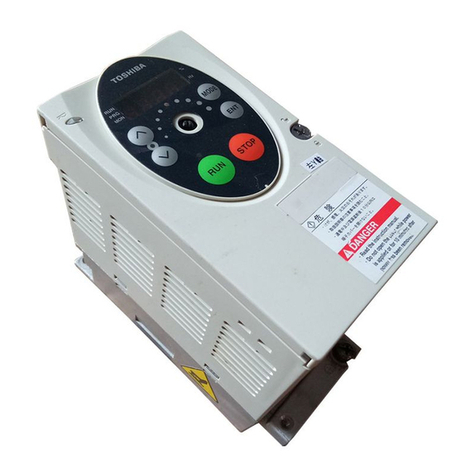
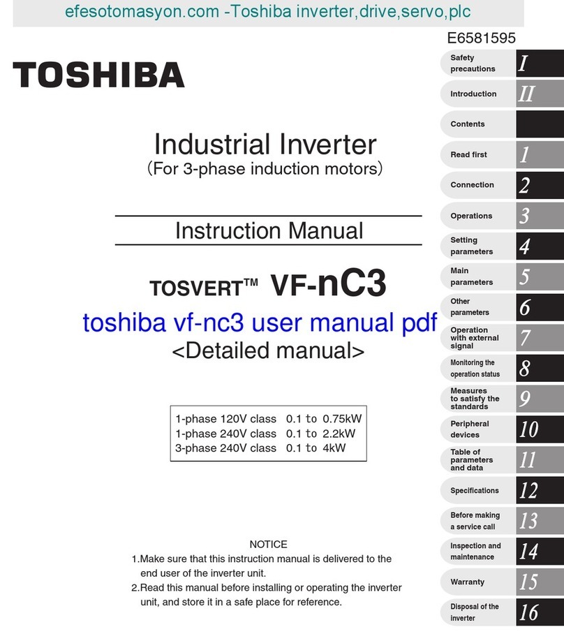
  9. Toshiba TOSVERT VF-nC3 User manual

Toshiba TOSVERT VF-nC3 User manual

Variable Speed Drive
For users of the products : Our variable speed drives are designed to control the speeds of three-phase motors for general industry.
For further information, please contact your nearest Toshiba Representative or International Operations-Producer Goods.
The information in this brochure is subject to change without notice.
Precautions
* Please read the instruction manual before installing or operating the drive unit.
* This product is intended for general purpose uses in industrial application. It cannot be used applications where may cause big impact on public
uses, such as power plant and railway, and equipment which endanger human life or injury, such as nuclear power control, aviation, space flight
control, traic, safety device, amusement, or medical.
It may be considerable whether to apply, under the special condition or an application where strict quality control may not be required. Please
contact our headquarters, branch, or local oices printed on the front and back covers of this catalogue.
* When exporting Toshiba variable speed drive separately or combined with your equipment, please be sure to satisfy the objective conditions
and inform conditions listed in the export control policies, so called Catch All restrictions, which are set by the Ministry of Economy, Trade and
Industry of Japan, and the appropriate export procedures must also be taken.
* Please use our product in applications where do not cause serious accidents or damages even if product is failure, or please use in environment
where safety equipment is applicable or a backup circuit device is provided outside the system.
* Please do not use our product for any load other than three-phase motors.
* None of Toshiba, its subsidiaries, ailiates or agents, shall be liable for any physical damages, including, without limitation, malfunction, anomaly,
breakdown or any other problem that may occur to any apparatus in which the Toshiba variable speed drive is incorporated or to any
equipment that is used in combination with the Toshiba variable speed drive. Nor shall Toshiba, its subsidiaries, ailiates or agents be liable for
any compensatory damages resulting from such utilization, including compensation for special, indirect, incidental, consequential, punitive or
exemplary damages, or for loss of profit, income or data, even if the user has been advised or apprised of the likelihood of the occurrence of such
loss or damages.
Global Sales DepartmentMotor Drive Division
580, Horikawa-cho,Saiwai-ku, Kawasaki, Kanagawa 212-0013, Japan Tel :+81-44-520-0828 Fax :+81-44-520-0508
http://www.toshiba-tips.co.jp/en/ CKVJ-1133
2019-08 TBLS
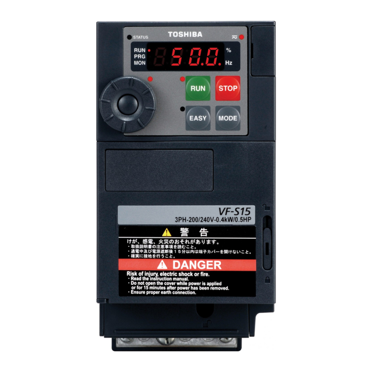
The Extension panel option allows to operate the
VF-nC3 in front of the cabinet.
An extension panel option installed on the surface of the cabinet can operate
the VF-nC3 in front of the cabinet.
It is possible to monitor the output frequency on the VF-nC3 and the output current
on the extension panel option (RKP007Z). It is possible to use it as a digital meter.
*The extension panel option is connected to the inverter with the optional cable.
In the extension panel option, there is no setting dial.
Extension panel option <RKP007Z>
 Easy mode : Scrolls through a list of only seven parameters.
You can optionally add up to 24 parameters to the list.
 Standard mode : Rotates through all parameters.
Built-in RS485 communication
Built-in RS485 communication enable to control the inverter and build network.
  ◯ Communication rate : 38.4 kbps max.
  ◯ Compatible with the Modbus RTU and Toshiba protocols.
You can connect a PC to manage parameters and monitor operating conditions. A RJ45 connector for RS485 communication is
located on the bottom of the VF-nC3.
 
*1: The maximum output current may be limited or the label at the top of the unit
need be removed, depending on the operating conditions.
*2 You can use the Monitor mode through RS485 communication.
1. VF-nC3 can be controlled simultaneously through RS485 communication.
2. Each inverter can switch among multiple motors if their operations do not overlap in the course of a work
process. The VF-nC3 can toggle between the basic settings for two motors.
3. VF-nC3 units can be installed side by side to save control panel space.
Base frequency
voltage 1&2
The inverter input voltage (DC detection) (%/V) is displayed.
( In case of=)
 Explanation of the name plate label
3-phase 240V class
Item Specification
Input voltage class
Applicable motor (kW)
3-phase 240V class
VFNC3
3-phase 200V to 240V
150-60 seconds, 200%-0.5 second
3-phase 200V to 240V - 50/60Hz
Voltage 170 to 264V Note 4), frequency ±5%
RAL 3002 / 7016
IP20
0.1
Self-cooling Forced air-cooled
0.2 0.4
2001P
0.3
0.7(0.7)
2002P
0.6
1.4(1.4)
2004P
1.0
2.4(2.4)
2007P
1.6
4.2(3.6)
0.75 1.5 2.2 4.0
0.5 0.8 1.4 2.5 4.3 5.7 9.2
Type
Form
Rating
Power
supply
Output Capacity (kVA) Note 1)
1-phase 240V class / 1-phase 120V class
Item
Input voltage class
Applicable motor (kW)
Specification
1-phase 240V class
Note 1. Capacity is calculated at 220V for output voltage.
Note 2. Indicates rated output current setting when the PWM carrier frequency (parameter ) is 4kHz or less. Between 5 kHz and 12 kHz, the rated output current is indicated in the ( ). Above
13 kHz, the output current must be reduced. The default setting of the PWM carrier frequency is 12kHz.
Note 3. Maximum output voltage is the same as the input voltage. In case of 1-phase 120V class, maximum output voltage is same as twice the input voltage.
With regard to 120V models, the output voltage may decrease about 10 to 20 % if motor load is applied. When operating VF-nC3 in conjunction with general-purpose motor (200V),
it is necessary to reduce the motor load.
Note 4. 180V-264V (240V class), 90V-132V (120V class) when the inverter is used continuously (load of 100%).
Note 5. Required power supply capacity varies with the value of the power supply side inverter impedance (including those of the input reactor and cables).
VFNC3S VFNC3S
3-phase 200V to 240V
150-60 seconds, 200% -0.5 second
1-phase 200V to 240V - 50/60Hz
Voltage 170 to 264V Note 4), frequency ±5%
3-phase 200V to 240V
150-60 seconds, 200%-0.5 second
1-phase 100V to 120V – 50/60Hz
Voltage 85 to 132V Note 4), frequency±5
RAL 3002 / 7016
EMC filter
IP20
0.1
Self-cooling Forced air-cooled
1-phase 120V class
RAL 3002 / 7016
IP20
Self-cooling
Forced air-cooled
0.2 0.4
2001PL
0.3
0.7(0.7)
2002PL
0.6
1.4(1.4)
2004PL
1.0
2.4(2.4)
2007PL
1.6
4.2(3.2)
2015PL
2.9
7.5( 7.5)
2022PL
3.9
10.0(9.1)
0.75 1.5 2.2 0.1
1001P
0.3
0.7(0.7)
0.2
1002P
0.6
1.4(1.4)
0.4
1004P
1.0
2.4(2.4)
1007P
1.6
4.2(4.0)
0.75
0.5 0.8 1.3 2.3 4.0 5.4 0.4 0.7 1.3 2.1
Type
Form
Output Capacity (kVA) Note 1)
Rating
Output current(A) Note 2)
Output voltage Note 3)
Overload current rating
Voltage-frequency
Allowable fluctuation
R
equired Power supply capacity (kVA) Note 5)
Protective method (IEC60529)
Cooling method
Color
Built-in filter
Output current(A) Note 2)
Output voltage Note 3)
Overload current rating
Voltage-frequency
Allowable fluctuation
Required Power supply capacity (kVA) Note 5)
Protective method (IEC60529)
Cooling method
Color
Built-in filter
Power
supply
2015P
2.9
7.5( 7.5)
2022P
3.9
10.0(8.5)
2037P
6.4
16.7(14.0)
Voltage class Applicable
motor (kW) Inverter type Dimensions (mm)
W H D W1 H1 H2 Drawing Approx.
weight(kg)
0.1
0.2
0.4
0.75
1.5
2.2
4.0
0.1
0.2
0.4
0.75
1.5
2.2
0.1
0.2
0.4
0.75
3-phase 240V
1-phase240V
VFNC3-2001P
VFNC3-2002P
VFNC3-2004P
VFNC3-2007P
VFNC3-2015P
VFNC3-2022P
VFNC3-2037P
VFNC3S-2001PL
VFNC3S-2002PL
VFNC3S-2004PL
VFNC3S-2007PL
VFNC3S-2015PL
VFNC3S-2022PL
VFNC3S-1001P
VFNC3S-1002P
VFNC3S-1004P
VFNC3S-1007P
72
102
121
131
156
141
60
93
126 157 14
13
13
13
C
60
93
60
93
131
131
131
118
121
131
121
156
102
102
105
140
130
170
72
72
105
105
1-phase120V
130
130
118
118
12
12

B
B
B
A
A
2.0
1.0
1.0
1.0
1.5
1.5
1.5
Note 1. H2 : Height of EMC plate mounting area
Note 2. Here are the available EMC plate
Fig.A : EMP007Z (Approx. weight : 0.3kg)
Fig.B : EMP008Z (Approx. weight : 0.4kg)
Fig.C : EMP009Z (Approx. weight : 0.5kg)
Note 3. The models shown in Fig. A to Fig. B are
fixed at two points: in the upper left and
lower right corners.
Note 4. The model shown in Fig. A is not
equipped with a cooling fan.
The models of 1-phase 240V and 1-phase
120V shown in Fig.B are equipped with a
cooling fan on the top of the unit.
Note 5. Height measurements do not include the
protrusions for installation.
Digital setting: within ±0.1% of the max. frequency (-10 to +60°C)
Analog setting: within ±1.0% of the max. frequency (25°C ±10°C)
Setting dial on the front panel, external frequency potentiometer (connectable to a potentiometer with a rated impedance of 1k - 10kΩ),
0 - 10Vdc / 0 - 5Vdc (input impedance: VI=40kΩ, 4 - 20mAdc (Input impedance: 250Ω). Note 1)
The characteristic can be set arbitrarily by two-point setting. Possible to set: analog input (VI).
Setting of the jump frequency and the range.
Upper-limit frequency: 0 to max. frequency, lower-limit frequency: 0 to upper-limit frequency
Adjustable within a range of 2k to 16kHz (default: 12kHz).
Braking start-up frequency: 0 to maximum frequency, braking rate: 0 to 100%, braking time: 0 to 25.5 seconds, emergency DC braking.
None (braking module is optional)
The RUN and STOP keys on the operation panel are used to start and stop operation, respectively.
Forward/reverse run possible through communication and logic inputs from the terminal block.
1c-contact output: (250 V ac - 2 A (cosΦ=1): At resistive load, 30 V dc -1 A, 250 V ac - 1 A (cosΦ=0.4))
Over-current, overvoltage, overheat, output short-circuit., ground fault, inverter overload, over-current through arm at start-up,
over-current through load at start-up, CPU fault, EEPROM fault, RAM fault, ROM fault,communication error. (Selectable:
emergency stop, under-voltage, small current, over-torque, motor overload, input phase failure, output phase failure)
Operation frequency, operation frequency command, forward/reverse run, output current, input voltage (DC detection),output voltage,
torque, torque current, load factor of inverter, input power, output power, information on input terminals, information
on output terminals, version of CPU1, version of CPU2, PID feedback value, frequency command (after compensation),
logic input terminals setting, causes of past trips 1 to 4, parts replacement alarm, cumulative operation time
Stores data on the past four trips: number of trips that occurred in succession, operation frequency, direction of rotation, load current, input voltage
(DC detection), output voltage, information on input terminals, information on output terminals, and cumulative operation time when each trip occurred.
Analog output for meter: 1 mA dc full-scale dc ammeter
0 - 20 mA (4 to 20 mA) output: DC ammeter (allowable load resistance: Less than 750 Ω)
0 - 10 V output: DC voltmeter (allowable load resistance: Over 1kΩ)
Indoors; not exposed to direct sunlight, corrosive gas, explosive gas, flammable gas, oil mist, or dust; and vibration of less than 5.9 m/s
2
(10 to 55 Hz).
3000 m or less (current reduction required over 1000 m) Note 2)
-10 to +60°C Note 3)
-25 to +70°C
5 to 95% (free from condensation and vapor).
Note 1. Be careful, if 4-20mA is selected, when the inverter's power is ON, the internal impedance is 250Ω, but when the power is OFF, the internal impedance increases very much to
approximately 40kΩ.
Note 2. Current must be reduced by 1% for each 100 m over 1000 m. For example, 90% at 2000 m and 80% at 3000 m.
Note 3. Above 40°C : Remove the protective seal from the top of VF-nC3.
Above 50°C: Remove the seal from the top of the inverter and use the inverter with the output current reduced.
Side by side installation (with no space between inverters): Remove the seal from the top of each inverter. When installing the inverter where the ambient temperature will rise above
40°C, remove the seal from the top of the inverter and use the inverter with the output current reduced.
Jog mode, if selected, allows jog operation from the terminal board.
Frequency reference +15-speed operation possible by changing the combination of 4 contacts on the terminal board.
Capable of restarting automatically after a check of the main circuit elements in case the protective function is activated. 10 times (Max.) (selectable with a parameter)
V/f constant, variable torque, automatic torque boost, vector control, automatic energy-saving. Auto-tuning.
Base frequency (20 - 400Hz) adjusting to 1 & 2, torque boost (0 - 30%) adjusting to 1 & 2, adjusting frequency at start (0.1 - 10Hz)

*1: Main circuit power supply
3ph-240V class: three-phase 200-240V-50/60Hz
1ph-240V class: single-phase 200-240V-50/60Hz
1ph-120V class: single-phase 100-120V-50/60Hz
*2: The inverter is supplied with the PO and the PA/+ terminals shorted by means of a shorting bar.
Before installing the DC reactor (DCL), remove the bar.
*3: When using the OUT output terminal in sink logic mode, short the NO and CC terminals.
When using the NO output terminal in source logic mode,short the P24 and OUT terminals.
*4: 1ph-240V models have noise filter inside.
*5: 1ph-120V models cannot be used with DC reactors.
*6: When external potentiometer is connected by using P5 terminal, set the parameter f109=3
*7: When using VI terminal as a logic input terminal, set the
parameter f109=2 and connect as following
schematics. Be sure to connect a resistor between
P24 and VI terminals in case of sink logic, between
VI and CC terminals in case of source logic.
(Recommended resistance: 4.7k -1/2W)
The T/L3 terminal is not provided for
single-phase models.
Use the R/L1 and S/L2/N terminals as input terminals.



Single phase
power supply
< Sink logic > < Source logic >
Note 1. Be sure to attach a surge killer to the exciting coil of the relay and the magnetic contactor.
Note 2. When using the auxiliary contacts 2a of the magnetic contactor MC for the control circuit, connect the contacts 2a in parallel to increase reliability.
Note 3. When a motor is driven by commercial power supply using commercial power supply / inverter switching circuit, use a magnetic contactor appropriated AC-3 class the motor rated current.
Note 4. Select an MCCB with a rataed interrupting current appropriate to the capacity of the power supply, because short-circuit currents vary greatly depending on the capacity of the power supply
and the condition of the wiring system. The MCCB, MC and ELCB in this table were selected, on the assumption that a power supply with a normal capacity would be used.
Note 5. Sizes of the wires connected to the input terminals R/L1, S/L2 and T/L3 and the output terminals U/ T1, V/T2 and W/T3 when the length of each wire does not exceed 30m.
The numeric values in parentheses refer to the sizes of wires to be used when a DC reactor is connected.
Note 6. For the control circuit, use shielded wires 0.75 mm2 or more in diameter.
Note 7. For grounding, use a cable with a size equal to or larger than the above.
Note 8. The wire sizes specified in the above table apply to HIV wires (cupper wires shielded with an insulator with a maximum allowable temperature of 75°C) used at an ambient temperature of 50°C or less.
Voltage
class
3-phase
240V
Inverter type
Molded -case circuit breaker (MCCB)
Earth leakage circuit breaker (ELCB) Note4)
Magnetic contactor (MC)
Note1) 2) 3)
Applicable
motor
(kW)
Rated current (A)Rated current (A)
Input current (A)
No reactor With DC
reactor
No reactor With DC
reactor
No reactor With DC
reactor
Main circuit
Note5) DC reactor
(optional)
Grounding
cable
Note7)
Wire size (mm2)Note8)
0.1
0.2
0.4
0.75
1.5
2.2
4.0
0.1
0.2
0.4
0.75
1.5
2.2
0.1
0.2
0.4
0.75
VFNC3-2001P
VFNC3-2002P
VFNC3-2004P
VFNC3-2007P
VFNC3-2015P
VFNC3-2022P
VFNC3-2037P
VFNC3S-2001PL
VFNC3S-2002PL
VFNC3S-2004PL
VFNC3S-2007PL
VFNC3S-2015PL
VFNC3S-2022PL
VFNC3S-1001P
VFNC3S-1002P
VFNC3S-1004P
VFNC3S-1007P
1-phase
240V
1-phase
120V
1.2
2.0
3.6
6.3
11.1
14.9
23.8
2.0
3.4
5.9
10.2
17.8
24
3.5
6.0
11.4
18.9
0.6
0.9
1.8
3.5
6.6
9.3
16.1
1.2
2.1
4.1
7.7
14.8
20.3
−
−
−
−
5
5
5
10
15
20
30
5
5
10
15
30
30
5
10
15
30
20
20
20
20
20
20
32
20
20
20
20
20
32
20
20
20
20
20
20
20
20
20
20
20
20
20
20
20
20
32
−
−
−
−
1.5(1.5)
1.5(1.5)
1.5(1.5)
1.5(1.5)
1.5(1.5)
2.5(1.5)
4.0(2.5)
1.5(1.5)
1.5(1.5)
1.5(1.5)
1.5(1.5)
2.5(2.5)
4.0(4.0)
1.5
1.5
2.5
4.0
1.5
1.5
1.5
1.5
1.5
1.5
4.0
1.5
1.5
1.5
1.5
1.5
1.5
−
−
−
−
2.5
2.5
2.5
2.5
2.5
2.5
4.0
2.5
2.5
2.5
2.5
2.5
4.0
2.5
2.5
2.5
4.0
5
5
5
5
10
15
30
5
5
5
10
20
30
−
−
−
−
 Multifunction programmable logic input/output
MCCB
*1
R/L1
S/L2
T/L3
U/T1
V/T2
W/T3
Motor
F
R
S1
S2
CC
P24
OUT
NO
CC
FM CC VI P5
++
-
-
P0 PA/+ PC/-
Meter Voltage signal: 0-5V/0-10V
(Current signal: 4-20mA)
External potentiometer (1k-10k )
Protective function
activation output
Ry
VF-nC3
Power
circuit
Noise
filter
DC reactor (DCL)
*2 , *5 (option)
Forward
Reverse
Preset-speed 1
Preset-speed 2
Common
7.5V-1mA
(or 0-10V/4-20mA)
Low-speed
signal output
*3
*4
Control
circuit
I M
Frequency
meter
(ammeter)
Operation panel



RS485
communication
connector
*7
*6
MCCB
*1
R/L1
S/L2
T/L3
U/T1
V/T2
W/T3
Motor
NO
CC
++
-
-
P0
Meter
External potentiometer (1k-10k )
Control
circuit
Protective function
activation output
VF-nC3
Power
circuit
DC reactor (DCL)
7.5V-1mA
(or 0-10V/4-20mA)
FM CC VI P5
PA/+ PC/-
Voltage signal: 0-5V/0-10V
(Current signal: 4-20mA)
Low-Speed
signal output
Ry
*4
Noise
filter
I M
Frequency
meter
(ammeter)
RS485
communication
connector
Operation panel
*2 , *5 (option)



*7
*6
F
R
S1
S2
OUT
Forward
Reverse
Preset-speed 1
Preset-speed 2
*3
P24
Common
 Logic input terminal
3-pahse 240V class: three-phase 200 to 240V-50/60Hz
* Single-phase input: R/L1 and S/L2/N terminals
No voltage logic input
24Vdc-5mA or less
* Sink / Source selectable using
parameter
(Explanation in case of sink logic)
Multifunction programmable analog input.
Factory default setting: 0-10Vdc(10 bits resolution) and 0-60Hz (0-50Hz) frequency input.
The function can be changed to 4-20mAdc (0-20mA) current input by parameter =
1setting and 0-5Vdc (10 bits
resolution) voltage input by parameter =3setting.
By changing parameter =2setting, this terminal can also be used as a multifunction programmable logic
input terminal. Be sure to insert a resistor between P24-VI(4.7 k-1/2 W) in case of sink logic, between VI-CC in
case of source logic.
1mAdc full-scale ammeter
0-20mA (4-20mA) DC ammeter
Permissible load resistance:
750Ωor less
0-10V DC volt meter
Multifunction programmable analog output. Standard default setting: output frequency.
The function can be changed to 0-10Vdc voltage
or 0-20mAdc (4-20mA) current output by parameter setting.
Parameter Function Default settingAction
F
R
S1
S2
VI
Set the function number to each parameters.
In case of using one function, please set
  
.
In case of set two functions, OUT outputs by ‘AND’/’OR’ logic.
Select logic or pulse train output.
Set the function number.
2(Forward run)
0(No function)
0(No function)
4(Reverse run)
0(No function)
0(No function)
10(Preset-speed command 1)
0(No function)
12(Preset-speed command 2)
0(No function)
0(Voltage input signal 0 to 10V)
14(Preset-speed command 3)
Input terminal selection 1A
Input terminal selection 1B
Input terminal selection 1C
Input terminal selection 2A
Input terminal selection 2B
Input terminal selection 2C
Input terminal selection 3A
Input terminal selection 3B
Input terminal selection 4A
Input terminal selection 4B
Analog/ logic input selection (VI terminal)
Input terminal selection 5
Set f1 0 9 =2(Logic input) for logic input.
Set the function number.
Set the function number to each parameters.
Two or more functions can be set to one terminal.
All functions operate by the signal input
OUT
FL(A, B, C)
4(Low speed detection)
255(Always ON)
0(AND)
0(Logic)
10(Failure signal (trip output))
Output terminal selection 1A
Output terminal selection 1B
Output terminal logic selection
Logic output/pulse train output selection
Output terminal selection 2
 Logic output terminal

 
  
 
  
  
 
  
 
  
  
 
  
  
  

  
Terminal
symbol
Parameter Function Default settingAction
Terminal
symbol
Note) All of logic output terminals are turned off about 0.5 to 1 second when power-on and fault reset. Please pay attention to use negative logic outputs.
Note) When using the VI terminal as logic input terminal, be sure to connect a resistor between P24 and VI terminals in case of sink logic, between VI and CC terminals in case of source logic.
(Recommended resistance: 4.7k-1/2W)
Note) If 4-20mA is selected, when the inverter’s power is ON, the intertnal impedance is 250Ω, but when the power is OFF, the intertnal impedance increases very much to approximately 40kΩ.
 Standard connection diagram-(sink logic)
(Negative)(common:CC)
 Standard connection diagram-(source logic)
(Positive)(common:P24)
Open collector output 24Vdc-100mA
To output pulse trains, a current of
10mA or more needs to be passed.
Pulse frequency range: 381600pps
R/L1,S/L2,T/L3
U/T1,V/T2,W/T3
PC/-
PO, PA/+
F
R
CC
P5
VI
FM
P24
FLA
FLB
FLC
S1
S2
OUT
NO
0.1: -
2: Preset speed guidance
3: Analog signal operation guidance
4: Motor 12 switching operation guidance
5: Motor constant setting guidance
0: Terminal board
1: Panel keypad (including extension panel)
2: RS485 communication
0: Terminal board VI
1: Setting dial 1(Press the center to save)
2: Setting dial 2 (save even if power is off)
3: RS485 communication
4: -
5: UP/DOWN from external logic input
0: Output frequency
1: Output current
2: Frequency reference
3: Input voltage (DC detection)
4: Output voltage (command value)
12: Frequency setting value (after compensation)
13: VI input value
15: Fixed output 1 (output current 100%
eguinalent)
16: Fixed output 2 (output current 50% eguinalent)
17: Fixed output 3 (Other than the output current)
18: RS485 communication data
19: For adjustments ( set value is displayed.)
5 to11,14,20 to 22: -
0: Forward run
1: Reverse run
2: Forward run (F/R switching on extension panel)
3: Reverse run (F/R switching on extension panel)
0: Standard setting mode at power on
1: Easy setting mode at power on
2: Easy setting mode only
Always active function selection 2
0:0-10V
1:4-20mA
2:Logic input
3:0-5V
Output terminal logic selection
(OUT)
0:

0:
 or 
and 
No function assigned
Forward run command
Reverse run command
Stand by
Reset command
Preset-speed command 1
Preset-speed command 2
Preset-speed command 3
Preset-speed command 4
Jog run mode
Emergency stop by external signal
DC braking command
2nd Acceleration/deceleration
2nd V/F setting switching
2nd stall prevention level
PID control prohibition
Switching from communications to local
Operation hold (hold of 3-wire operation)
PID integral/derivative clear
PID characteristics switching
Frequency UP signal input from ex ternal contacts
Frequency DOWN signal input from external contacts
Clear frequency UP/DOWN signal input from
external contacts
Coast stop command
Switch to frequency command terminal board
Command mode terminal board
Parameter editing permitted
Forced deceleration command
Parameter editing prohibit
Frequency lower limit
Frequency upper limit
Low-speed detection signal
Output frequency arrival signal
(acceleration/deceleration completed)
Designated frequency arrival signal
Fault signal (trip output)
Overcurrent detection pre-alarm
Overload detection pre-alarm
Overheat detection pre-alarm
Overvoltage detection pre-alarm
Main circuit undervoltage detection
Small current detection
Over-torque detection
Run/stop
Cumulative operation time alarm
Forward/reverse run
RS485 communications error
Designated data output
Parts replacement alarm
Fault signal (output also at a retry)
Always OFF / ON
0, 1, 2, 18, 52
0, 1, 2, 18, 52
VI Input point 1 setting
VI Input point 1 frequency
VI Input point 2 setting
VI Input point 2 frequency
Supply voltage corrensation
(output voltage limit)
Motor rated speed
Logic output/pulse train output selection (OUT)
Pulse train output function selection (OUT)
Baud rate
0, 1, 3, 4, 5
Hysteresis for lower-limit freguency operation
Small current detection hysteresis
Detection of output short-circuit at start-up
Over-torque detection hysteresis
0: Permitted, 1: Panel and extension panel inhibited
2: 1 + RS485 communication inhibited
Local / remote key prohibition of extension panel
Panel emergency stop operation prohibition
Panel reset operation prohibition
Password rerification
0
610.0
0: Operation frequency, 1: Output current, 2: Frequency setting value,
3: Input voltage (DC detection), 4: Output voltage (command value) ,
5: Input power, 6: Output power, 7: Torque, 8: Torque current,
12: Frequency setting value (after compensation),
23: PID feedback value, 27: Drive load factor, 52: Frequency setting
value / operation frequency
Easy setting mode parameter 1~24
High-attenuation
radio noise reduction
llter
Zero-phase reactor
core-type radio noise
reduction llter
DIN rail kit
Simple radio
noise reduction llter
Zero-phase reactor
core-type radio noise
redction llter
Use when rapid deceleration or stop is frequently required or when it
is desired to reduce the deceleration time with large load.This
module and resistor consumes regenerative energy during power
generation braking. For 0.1 to 2.2kW models. <Type: BRMD0015Z>
Use to mount the inverter on DIN rails. For 0.1 to 2.2kW models.
<Type:DIN003Z, DIN005Z>
LED remote keypad is for extension. It is provided with an LED display,
some operational keys.
The panel with parameter writer function can setup and read the
parameters for inverter.
ZW
S/L2/N
High-attenuation
radio noise
reduction lter
(NF type)
Simple radio
noise reduction
lter
(capacitive lter)
Zero-phase
reactor
core-type
radio noise
reduction lter
Zero-phase reactor
(inductive lter)
core type
P.7
If the cable
thickness is
5.5mm2or more,
please select
RC9129ZZT.
RC5078ZZ
GA B C D E F
55 405
55 405
60 505
60 505
M 3.5
PFL-2001S 105 65 115 90 1.0
PFL-2005S 105 65 115 90 M 3.5 1.2
PFL-2011S 2007PL 130 70 140 115 M4 2.3
PFL-2018S 2037P 2015PL,2022PL
1004P,1007P
2001PL,2002PL
2004PL,1001P,1002P
2001P,2002P
2004P,2007P
2015P,2022P
130 70 140 115 M4 2.5
Model Rating
Inverter type Dimensions(mm)
Terminal
(Terminal block
Approx.
mass
(kg)
VFNC3- VFNC3S-
3-phase 200V class
-18A-50/60Hz
3-phase 200V class
-11A-50/60Hz
3-phase 200V class
-5.5A-50/60Hz
3-phase 200V class
-1.7A-50/60Hz
Model Inverter type Dimensions(mm)
VFNC3- VFNC3S-
Approx.
mass
(kg)
Rated
current
(A) A B C E F G H J K M N P
NF3005A-MJ 5
2001P
2002P
2004P
2007P
1001P
174.5 160 145 110 80 32 70 20 45 5.5 M4 M4
1.0
NF3015A-MJ 15 2015P
2022P
1002P
1004P 1.6
NF3020A-MJ 20 2037P 1007P
RC5078ZZ
RC5078ZZ
DCL3-4004
DCL3-4007
DCL3-4015
DCL3-2007
DCL3-2015
DCL3-2022
DCL3-2037
DCL3-4007
DCL3-4015
DCL3-2007
DCL3-2015
DCL3-2037
DCL3-2037
PFL-2001S
PFL-2001S
PFL-2005S
PFL-2005S
PFL-2011S
PFL-2011S
PFL-2018S
PFL-2005S
PFL-2005S
PFL-2005S
PFL-2011S
PFL-2018S
PFL-2018S
PFL-2005S
PFL-2005S
PFL-2018S
PFL-2018S
Note1)
Note 1: Use the portion where the varnish around the installation hole
is removed for wiring grounding wire.
DC reactor
PA
PA/+ PO
PO
R/L1
S/L2
T/L3
U/T1
V/T2
W/T3
VF-nC3
Power
supply IM

 
Note2, 3)
Grounding terminal (Mounting hole)
Note1)
Terminal box with cover
Screw C
E
Note 1: Use the portion where the varnish around the installation
hole is removed for wiring grounding wire.
Note 2: Remove the jumper across terminals PO-PA/+.
Note 3: Maximum wire length is 5m.
B(Mounting
dimension)
Model Inverter type Dimensions(mm)
VFNC3- VFNC3S- EW H D A B C
2004PL
2007PL

2015PL, 2022PL

2001PL
2002PL
75
96
75
2007P
2015P
2022P
2037P
2001P
2002P
2004P
DCL3-2007
DCL3-2015
DCL3-2022
DCL3-2037
DCL3-4004
DCL3-4007
DCL3-4015
Approx.
mass
(kg)
116
118
116
1.0
1.0
1.1
2.2
1.0
1.0
1.0
5
5
5
M4
M4
M4
51
66
51
54
66
54
78
100
78
Approx. mass: 85g
Type : RC5078ZZ Type : RC9129ZZT
Unit: 
Approx. mass: 0.38kg
23
26
14
7
5
46
82.5
84.5
130
150
Approx. mass: 1.1kg
31.5
160
180
15
7
7
25 35
85
8
135
85
RC9129ZZT
A(Mounting
dimension)
2019/8/20改定修正版
4-φ4
16.4
63±0.3
10.4
31
98±0.3
4.6
Communication cable (option). Model :
CAB0071(1m),CAB0073(3m), CAB0075(5m)
Communication cable (option). Model : CAB0011(1m). CAB0013(3m).
CAB0015(5m)
Inverter unit connection cable.
Model:CAB0011(1m). CAB0013(3m). CAB0015(5m).
USB cable(A-B connection type).
USB a commercially available USB cable. (Compliant with USB1.1/2.0)
Recommended cable length : 1m or less
60
5
3.2
1
219.6
88
1
19.9 31.6
90
112
16
5
9
13.2
19.6
27.1
3.2
45°
2.8
TOSHIBA
80
80 H z- 1 m A dc Q S60T
Hz
20
40
60
0
13
10
25.5 17
φ
52
60
60
Panel cutout dimension
Panel cutout
dimension
*Dot line shows a
key cover location
4-φ4
φ28
54
29.2
34
17. 5
29.42.3
underwater motors have higher rated
When the lengths of the motor cable are long,
please use thicker cable than a table of "Wiring
devices" because the maximum torque is
decreased by the voltage dropping. Moreover,
please pay attention to select leakage circuit
breakers.
Variable Speed Drive
For users of the products : Our variable speed drives are designed to control the speeds of three-phase motors for general industry.
For further information, please contact your nearest Toshiba Representative or International Operations-Producer Goods.
The information in this brochure is subject to change without notice.
Precautions
* Please read the instruction manual before installing or operating the drive unit.
* This product is intended for general purpose uses in industrial application. It cannot be used applications where may cause big impact on public
uses, such as power plant and railway, and equipment which endanger human life or injury, such as nuclear power control, aviation, space flight
control, traic, safety device, amusement, or medical.
It may be considerable whether to apply, under the special condition or an application where strict quality control may not be required. Please
contact our headquarters, branch, or local oices printed on the front and back covers of this catalogue.
* When exporting Toshiba variable speed drive separately or combined with your equipment, please be sure to satisfy the objective conditions
and inform conditions listed in the export control policies, so called Catch All restrictions, which are set by the Ministry of Economy, Trade and
Industry of Japan, and the appropriate export procedures must also be taken.
* Please use our product in applications where do not cause serious accidents or damages even if product is failure, or please use in environment
where safety equipment is applicable or a backup circuit device is provided outside the system.
* Please do not use our product for any load other than three-phase motors.
* None of Toshiba, its subsidiaries, ailiates or agents, shall be liable for any physical damages, including, without limitation, malfunction, anomaly,
breakdown or any other problem that may occur to any apparatus in which the Toshiba variable speed drive is incorporated or to any
equipment that is used in combination with the Toshiba variable speed drive. Nor shall Toshiba, its subsidiaries, ailiates or agents be liable for
any compensatory damages resulting from such utilization, including compensation for special, indirect, incidental, consequential, punitive or
exemplary damages, or for loss of profit, income or data, even if the user has been advised or apprised of the likelihood of the occurrence of such
loss or damages.
Global Sales DepartmentMotor Drive Division
580, Horikawa-cho,Saiwai-ku, Kawasaki, Kanagawa 212-0013, Japan Tel :+81-44-520-0828 Fax :+81-44-520-0508
http://www.toshiba-tips.co.jp/en/ CKVJ-1133
2019-08 TBLS

Other manuals for TOSVERT VF-nC3

3

Other Toshiba Inverter manuals

Toshiba VF5X User manual

Toshiba

Toshiba VF5X User manual

Toshiba TOSVERT VF-A7 User manual

Toshiba

Toshiba TOSVERT VF-A7 User manual

Toshiba TOSVERT VF-MB1 User manual

Toshiba

Toshiba TOSVERT VF-MB1 User manual

Toshiba TOSVERT VF-AS1 Series User manual

Toshiba

Toshiba TOSVERT VF-AS1 Series User manual

Toshiba TOSVERT VF-S15 series Instruction manual

Toshiba

Toshiba TOSVERT VF-S15 series Instruction manual

Toshiba TOSVERT-130H Instructions for use

Toshiba

Toshiba TOSVERT-130H Instructions for use

Toshiba VF-NC3C User manual

Toshiba

Toshiba VF-NC3C User manual

Toshiba VFNC3-2001P User manual

Toshiba

Toshiba VFNC3-2001P User manual

Toshiba TOSVERT VF-AS1 Series User manual

Toshiba

Toshiba TOSVERT VF-AS1 Series User manual

Toshiba TOSVERT VF-MB1 User manual

Toshiba

Toshiba TOSVERT VF-MB1 User manual

Toshiba TOSVERT VF-AS3 User manual

Toshiba

Toshiba TOSVERT VF-AS3 User manual

Toshiba ACE-tronics G9 ASD User manual

Toshiba

Toshiba ACE-tronics G9 ASD User manual

Toshiba BACnet BCN001Z Parts list manual

Toshiba

Toshiba BACnet BCN001Z Parts list manual

Toshiba TOSVERT VF-AS1 Series User manual

Toshiba

Toshiba TOSVERT VF-AS1 Series User manual

Toshiba DEV001Z Parts list manual

Toshiba

Toshiba DEV001Z Parts list manual

Toshiba TOSVERT IPE001Z User manual

Toshiba

Toshiba TOSVERT IPE001Z User manual

Toshiba TOSVERT VF-P7 User manual

Toshiba

Toshiba TOSVERT VF-P7 User manual

Toshiba TOSVERT VF-AS1 Series User manual

Toshiba

Toshiba TOSVERT VF-AS1 Series User manual

Toshiba TOSVERT VF-AS1 Series User manual

Toshiba

Toshiba TOSVERT VF-AS1 Series User manual

Toshiba TOSVERT-130P2 User manual

Toshiba

Toshiba TOSVERT-130P2 User manual

Toshiba TOSVERT VF-AS3 User manual

Toshiba

Toshiba TOSVERT VF-AS3 User manual

Toshiba ACE-tronics G9 ASD Guide

Toshiba

Toshiba ACE-tronics G9 ASD Guide

Toshiba TOSVERT VF-S11 Configuration guide

Toshiba

Toshiba TOSVERT VF-S11 Configuration guide

Toshiba TOSVERT VF-FS1 Series Parts list manual

Toshiba

Toshiba TOSVERT VF-FS1 Series Parts list manual

Popular Inverter manuals by other brands

Avtech AVD series instructions

Avtech

Avtech AVD series instructions

gefran VDI100 Series instruction manual

gefran

gefran VDI100 Series instruction manual

Sima STP-150 User instructions

Sima

Sima STP-150 User instructions

Wagan Smart AC user manual

Wagan

Wagan Smart AC user manual

Power Tec 365S Operator's manual

Power Tec

Power Tec 365S Operator's manual

Stober POSIDRIVE FDS 5000 series manual

Stober

Stober POSIDRIVE FDS 5000 series manual

DORNA TECHNOLOGY DLA1 Series user manual

DORNA TECHNOLOGY

DORNA TECHNOLOGY DLA1 Series user manual

TOYODenki VF66 EIP66-Z operating manual

TOYODenki

TOYODenki VF66 EIP66-Z operating manual

Link electronics Genflex SPG-812/SA Specification sheet

Link electronics

Link electronics Genflex SPG-812/SA Specification sheet

GYS CONVERGYS 150 quick start guide

GYS

GYS CONVERGYS 150 quick start guide

ABB PVS-175-TL Series Quick installation guide

ABB

ABB PVS-175-TL Series Quick installation guide

Solax Adapter Box Quick installation guide

Solax

Solax Adapter Box Quick installation guide

Honeywell HW1000i - Portable Inverter Generator specification

Honeywell

Honeywell HW1000i - Portable Inverter Generator specification

Sensata Dimensions 12LP15 owner's manual

Sensata

Sensata Dimensions 12LP15 owner's manual

Envertech EVT800-B user manual

Envertech

Envertech EVT800-B user manual

Wagan SmartAC 425W user manual

Wagan

Wagan SmartAC 425W user manual

Paton PSI 270 PRO 400 V manual

Paton

Paton PSI 270 PRO 400 V manual

DUROMAX Duro Star DS4400E user manual

DUROMAX

DUROMAX Duro Star DS4400E user manual

manuals.online logo
manuals.online logoBrands
  • About & Mission
  • Contact us
  • Privacy Policy
  • Terms and Conditions

Copyright 2025 Manuals.Online. All Rights Reserved.