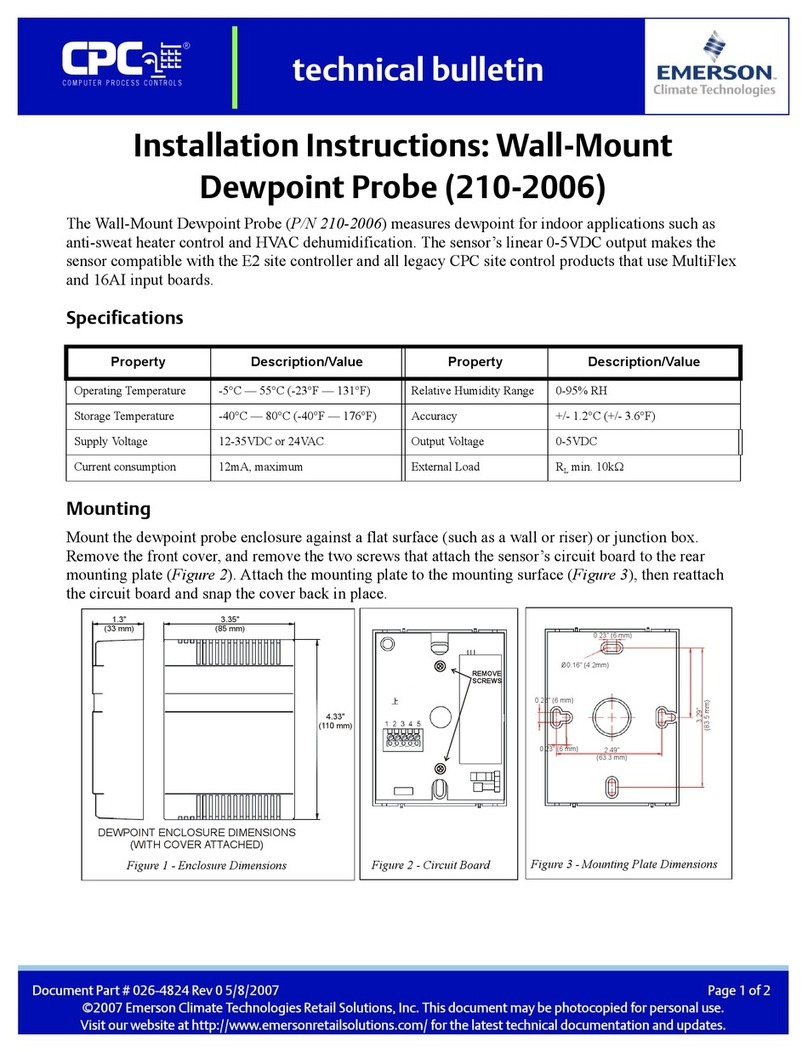
CPC LDS User manual

c?
Document No. 025-8261
Data. drawinos and other material
contained heiein are proprietary to
Computer Process Controlb, lnc. and may
not 'be reoroduced without the prior
approval of Computer Process Contrdls.
P.N. 809-1060
lnstallation and Oeration Manual
Version: 01/91
Computer Process Controls, lnc.
1275 Kennestone Circle
Suite 100
Marietta, Ga. 30066
(404) 425-2724
Model LDS
C?C*'*.ffi+
-
ZONE INDICAT1ON
oooooo
123156
-^MTmI-
eoe@e6
t23t56
lml lA
+- l7)1, - zou sE - F' | - l(/)l+
oooooo
123456
ALARM
SET POINT
@
SENSOR IEST
oa-*d**Y......ff
t23456
RESET
ALARH
@
LDS

ZONE
LDSZONELIST
DESCRIPTION
1
2
3
4
5
6
STORE #
ADDRESS

L D S Leak Detector Sysfem Manual
TABLE OF CONTENTS
SUBJECT PAGE
WHAT IS THE LDS? iii
1. INSTALLATION 1
A. MOUNTING CONTROL UNIT 1
B. MOUNTING SENSOR 1
2
A. LINE VOLTAGE AND FREOUENCY 2
B. GROUND 2
3. SENSOR CONNECTIONS 3
A. DISTANCE AND CABLE SIZE 3
B. WIRE COLORS AND SHIELD 3
4. ANALOG OUTPUTS 4
A. OUTPUT VOLTAGE 4
B. COMMON NEGATIVE, 6 POSITIVES 4
C. CABLING 4
5. FRONT PANEL 5
A. METER 5
B. ZONE SECTION 5
C. AI.ARM SECTION 5
D. DOOR I3TCH 5
6. SCAN MODE 6
A. FOR METER ONLY 6
B. SELECTING SCAN MODES 6
C. WHEN TO USE SCAN MODE 7
D. WHEN NOT TO USE SCAN MODE 7
7. INTERNAL JUMPERS 7
A. JU1 THROUGH JU6: R12 OR R22lR502 7
B. JU7 AND JU8: POWER INPUT VOLTAGE I
C. JU9: ALARM LATCH OR NO-I-ATCH I
-i-

t D S Leak Detector Sysfem Manual
TABLE OF CONTENTS CONT'D.
8. SENSOR TEST FUNCTION
A. FRONT PANEL DISPI.AY
B. SENSOR HEATER PROBLEMS
C. SENSOR ELEMENT PROBLEMS
D. ONE OR TWO PROBLEMS
9. INTERNAL INDICATORS
A. SENSOR HEATER OPEN
B. SENSOR HEATER SHORTED
C. SENSOR HEATER OK
10. ALARMS
A. SIX INDICATORS
B. ONE OUTPUT
11. CALIBRATION
A. METER ZERO
B. OFFSETS
C. AI.ARM SET POINTS
12. WARM UP
13. BATTERY
-ii-
8
I
I
I
I
I
I
I
10
10
10
10
10
10
10
11
11
11

L D S Leak Detector Sysfem Manual
What is the LDS?
The L D S Leak Detector System is a six channel refrigerant leak detector. lt has a
control box and one to six-remotely mounted sensors. lt continuously monitors all
sensors connected for alarm conditions
and provides a continous analog output
for each sensor.
It is powered by normal line voltage and
has alarm output contacts which may be
used in line voltage or low voltage
circuits.
The alarm trip point is separately
adjustable for each sensor. A meter on
the front of the control unit shows
refrigerant concentrations detected, and
is also used to show alarm trip points.
C?C *"* ffi
l'< (D( -I
l\rl
r-l
ll
ZONE IIiOICATION
oooooo
123456
-&1
FS-
g)6Oaee
123156
+ l7l - z te :*.. r r - - l72r-+
ta-
oooooo
123'1 56
e_____o_ *d* * 8.__6___-a
123156
RESET
ALARIl
@
iii-
a

L D S Leak Detector Sysfem Manual
l.INSTALLATION
o A. MOUNTING CONTROL UNIT
The control unit (the blue box with a meter
and buttons marked L D S, CPC part no.
809-1060) should be mounted on a wall in
an upright position. Do not mount it to
vibrating machinery because the meter
movement will not function correctly. Mount
the control box using four screws in the
mounting holes provided. The mounting
holes are spaced 8.0 inches (203mm) apart
horizontally, and 10.0 inches (254mm) apart
vertically. The correct mounting screw size
is 1/4 inch diameter (or 6mm diameter).
O B. MOUNTING SENSOR
Each sensor assembly (CPC part no.
809-1070) should be securely mounted in a MOUNTING DI|'1ENSIONS
place appropriate for detecting leaks. Consideration should be given to air flow patterns
in the aiea, which affect the ability of a detector to find a leak.
The sensor assembly may be mounted by screws through two holes in the extended flat
surface, or may be -mouhted by means of a stainless steel hose clamp (available at
hardware store-s). The hose clahp method is for attaching the sensor assemb.ly to- a
conduit or other pipe. The hose clamp may be routed through the two side notches for
attachment to vertical conduits, or through the slot and over the top for attachment to a
horizontal conduit.
The sensor assembly should be mounted with the sensor down and the mounting area
up, unless air flow conditions require a different orientation. Experimentation may be
required to determine optimum sensor location.
Be careful not to damage the sensor while handling and mounting the sensor assembly.
The sensor plugs into a socket on the sensor assembly bracket. lt may be plugged into
its socket either of the two ways it will go.
'1-
1,/4 (0ty[,1) DiA

L D S Leak Detector System Manual
2. POWER
o A. LINE VOLTAGE, FREQUENCY, AND POWER
The L D S control unit may be powered by 100 to 125 volts AC, or by 200 to 250 volts
AC. Jumpers (described later) set the line voltage range). The line voltage's frequency
may be 50 Hertz or 60 Hertz. See Paragraph 7.B tor 12OYl208V Jumpers.
The L D S draws up to 50 watts maximum. Typical power consumption will be 38 watts
with six sensors and all in alarm, down to 9 watts with one sensor connected and no
alarm. o B. GROUND
The L D S control unit should be properly grounded using the ground terminal on the
power input terminal block. This ground is also connected to signal common in the
bontrol unit. the grounded signal- common will be connected to all sensors and is
connected to the common the common negative of the analog outputs.
Fig. 1 LDS Wiring
@
=ill
I I Lt l r
,, llf aY Fl tJ2 F8 F2
1I,., r 8., z lI",: fi,- o E"u s 8,, 6 Eil'H[r-I
LA"...s'.'jre B'* ids:ry: dl.;:'E lg,:j* . Ei-;Hd*L!]_
-L -'.+m@B
Gr/ffi dH9 mrB d EAs, EM &Tare tr &
*C ,a Oe' Om' Oe" O*. Om- O*
l-l/-\]"2."3*2-1
w,f, V O*, O*, Q*r O*, O*, IHS N OI3CNCT
E @FED TO E.Eil
'2-
ooo
(.)@
\.-/
ANALOC
qJTPUT S

7
L D S Leak Detector SYsfem Manual
3. SENSOR CONNECTIONS
O A. DISTANCE AND CABLE SIZE
Each sensor assembly is to be connected
four-conductor-plus-shield-cable. The cable may be
longer lengths require larger guage cable.
to the control unit bY a
almost any practical length, but
300 feet
500 feet
750 feet
1250 feet
2000 feet
Conductor Maximum
24 AWG
22 AWG
20 AWG
18 AWG
16 AWG
There is no minimum length limit for any cable guage'
O B. WIRE COLORS AND SHIELD
It is recommended that the cable have white, black, red, and green insulation on its
Conductors, plus a foil shield with a separate drain wire for the shield. Stranded
conductors'(ihcluding the drain wire) will bb easier to handle and less likely to break in
most installations.
The white wire and the shield drain wire should be connected together at the control
box end. The shield drain wire may be left disconnected at the sensor end.
The proper order of the wires is marked on the board in the back of the control unit at
the tbrniinal blocks for the sensors. Each sensor connects to a separate terminal block,
sensor 1 to TB1, sensor 2toTB2, etc. See Fig. 1.
Each terminal block may be unplugged without removing wires from it if desired. lt will
also fit through a hole in-the bottom of the enclosure while wires are attached to it.
Any splices in the sensor cable should be well insulated, kept dry,.and should connect
all ioui colored conductors and also the shield drain wires together between cable ends.
A splice is an unshielded section of the overall cable, so should be located away.from
othbr electrical conductors. lf the splice must be close to other conductors,.locate it..in a
separate grounded metal box with hothing else r1 it (except.other sensor cables {splices
or'cable just passing through) to the same L D S control unit).
-3-

L D S Leak Detector SYsfem Manual
SENSOR CONNECTIONS CONtiNUEd
All sensor cables should be shielded and isolated from power circuits. Do NOT put them
in conduits containing power. They may be run in conduits containing gth.er shielded
analog signal cables to other equipment. Do not run together with digital data busses
such as RS232 or RS485.
4. ANALOG OUTPUTS
o A. OUTPUT VOLTAGE
Each analog output has a 0 volt to +5.0 volt DC range representing 0 to 1000 ppm
refrigerant concentration measured.
Sensor offsets (especially if not properly adjusted) can cause an analog output to go as
low as -0.10 voit. The analog oltputs 6an hot go any lower due to a clamping circuit in
each output.
Analog outputs can go higher than +5.0 volts if refrigerant concentration exceeds 1000
ppm. The highest possible output voltage is about + 10.5 volts.
A shorted analog output will not be damaged (unless it is shorted to a power source.),
and will not interiupt ihe alarm and meter functions of the L D S. Unused (open circuit)
analog outputs also do not affect the alarms and the meter.
. B. COMMON NEGATIVE, SIX POSITIVES
All six analog outputs share a common negative, marked 0V (zero volts). There are two
terminals for it.
The six analog outputs each have a separate terminal (on TB7) for the positive side.
The terminal block may be unplugged without removing wires from it if desired. lt will
also fit through a hole in the bottom of the enclosure while wires are attached to it.
o C. CABLING
Shielded cable is recommended when using the analog outputs. One of the 0V
terminals may be used for the common, and the other for the shield. The terminals are
marked (on terminal block TB7) accordingly. See Fig. 1.
-4'

L O S Leak Detector System Manual
ANALOG OUTPUTS CONtiNuEd
The analog outputs cable(s) should be located away from electrical interference. Do
NOT put tfiem in conduits containing power to anything. They may be run in conduits
containing other shielded analog signal cables to other equipment, but not together with
digital data busses such as RS232 or RS485).
lf the analog outputs cable(s) must be spliced, follow the recommendations above for
sensor cable splices.
5. FRONT PANEL
o A. METER
The meter at the top has a 0 to 1000 ppm (parts per million) scale. The meter is used to
view refrigerant concentrations and alarm trip points.
o B. ZONE SECTION
The operation of leak detection is controlled by the "ZONE INDICATION', 'ADJUST
OFFSET" AND "ZONE SELECT" indicators and controls on the front panel. lt has six
green lights to show which zone's (which sensor's) data is displayed on the meter; a
label for marking where the sensors are located; six offset adjustments; and two zone
select buttons. The zone select buttons select the zone to be displayed on the meter. lt
also selects one of two scanning modes as described in Paragraph 6.8.
o C. ATARM SECTION
The alarm section of the panel is the bottom portion, from ZONE ALARMS to ADJUST
AI-ARM SET POINT. lt controls all alarm functions, and also the sensor test mode.
These are described further, below.
. D. DOOR LATCH
Turn the silver colored door latch knob fully counter-clockwise until it stops to open the
door, and after closing the door turn it fully clockwise until it stops to hold the door shut.
-5-

L D S Leak Detector Sysfem Manual
6. SCAN MODE
O A. FOR METER ONLY
The scan mode is for the meter only. The scan mode is indicated by all six green lights
being on, with one flashing brightei. me scan modes go .slowly through zones which
havia sensor to allow the mete] to be read before proceeding to another zone, and go
quickly through unused zones and through zones which have a fault condition with the
sensoi, sincenalid data cannot be obtained from such zones.
There are two scan modes:
1) scanning from zone 1 to zone 6,
then repeating; 2) scanning in reverse
direction from 6 to 1, then repeating.
Choose the direction preferred, the data is
identical either way.
NOTE: The analog outputs and the alarm
functions are six independent circuits which
operate full time without any scanning. This
is true also when not scanning and the
meter is showing data for only one zone.
o B. SELECTING SCAN MODES
AND NON.SCAN MODES
To select the scan-up mode (zone 1 first,
then zone 2, etc.) push the left zone select
button enough times to make all six green
lights turn on. Scanning up will then begin.
To select the scan-down mode (zone 6
first, then zone 5, etc.) press the right zone
select button enough times to make all six
green lights turn on. Scanning down will
then begin.
It is also permissible to press and hold either zone select button which has the same
effect as pressing it severaltimes.
To select a single zone for display on the meter press either zone select button until the
green light of tlie desired zone is on steadily and all other green lights are off.
modes:
CPC *-*"E*ffi€EffitE
:3{E i{:::r=I,:}
oooooo
123456
_Mffi_
ce€o€e
123156
*@-:ff':i:::-@-
oooooo
\23150
ffi-*d"=B*--..-
t23456
'b-

L D S Leak Detector System Manual
o C. WHEN TO USE SCAN MODE
Use the scan mode for normal operation of the L D S after it has been installed and
adjusted.
o D. WHEN NOT TO USE SCAN MODE
Stop the scanning and select one zone when making adiustments to offsets or to the
alaim trip points, or when closely observing a leak in one zone.
The alarm and analog output functions are not altered by selecting.scanning 9r a single
zone. All zones continue to be monitored by all but the front panel meter. lt is not vital
that the unit be left in a scan mode when un--attended, but normally it should be.
T.INTERNAL JUMPERS
o A. JU1 THROUGH JU6: REFRIGERANT R12 OR R22|R5O2
Sensing refrigerant R12 takes more sensitivity than R22 or R502. lf a zone (sensor) is to
monitoi R12,1hen a jumper on the board in the back of the control unit mr-lst be plugged
onto the upper two pins (marked R12) for the corresponding 4ong. Otherwise, the
jumper snouiO be put in the R22lR502 position. (A missing jumper is the same as setting
it to the R221R5O2 position).
There are six such jumpers, One for eaCh zone marked 1, 2, 3, 4, 5, and 6. These
jumpers are also marked JU1 through JU6. I
See
Para
'.7.8.
["' r if "'' : iI'" : iL"" . B"' : fi" o
lCpr"s r u s, LJU/@ lll'r* lo r::-e2 lCR2?rc
!rMurls
e@e
sL r-.ffi@-E@rc
@/€sr Llm, mrH o E^E *M +ABs & &[
t.O ,a, O9 Ory O-i' Oi' 05" O*
mrQ V/ O*, Qwr Q*r Qwr O*,
-7-
o
n
lt
tl
olEtu Ft 1G2 *a t2
rsr &* ^* rA9 iw @
r---------r r-------r
Hl%HI'l"|Il _
., Hfl.E ld#ld*
-M
I tflr

t D S Leak Detector Sysfem Manual
O B. JU7 AND JU8: POWER INPUT VOLTAGE
The larger jumpers at the right side of the board in the back of the control unit marked
JU7 and JU8 are for selecting the line voltage range.
The MUST be set correctly BEFORE applying power to the L D S.
They must both be set to the same position (never one up and one down).
They should be set to the 120V position (down) for line voltage in the range 100 to 125
volts AC.
They should be set to the 208V position (down) for line voltage in the range 200 to 250
volts AC.
O C. JU9: ALARM LATCH OR NO-I.ATCH
On the board mounted on the door of the control unit is one jumper, marked JUg. lt
selects whether all six alarms will operate as TATCH or NO-I-ATCH.
I-ATCH (the upper position of the jumper) will cause any alarm to remain on until it is
manually resei by a'front panel buttbn, even if the leak that was detected has ceased.
NO |-ATCH (the lower position of the jumper) will cause any alarm to reset itself if a
detected leak ceases.
A missing jumper on JU9 will cause the last-selected mode at JU9 to remain selected.
No alarm can be reset if the detected leak is still present and above the alarm set point
level, regardless of the position of JU9.
8. SENSOR TEST FUNCTION
o A. FRONT PANEL DISPI-AY
The ALARM SET POINT and SENSOR TEST button causes the meter to show the alarm
set point on the meter, which is described further below. lt also causes the six red lights
on the front panel to indicate the status of the sensors.
While showing sensor status, the six red lights cease showing alarms. This action does
NOT reset alarms. Any alarms present will again be shown when the SENSOR TEST
button is released.
-8-

L D S Leak Detector Sysfem Manual
o B. SENSOR HEATER PROBLEMS
There are two conditions indicated by the SENSOR TEST function. The first is the state
of the sensor's heater. lf a sensor is present and correctly connected, it will show no
problem. lf it is not connected, or connected but open-circuited or shorted, it will
indicate a problem. This same heater detection circuit will also cause the scanning
modes to go quickly through a zone with a heater problem.
o C. SENSOR ELEMENT PROBLEMS
Sensor element problems (open circuit or short circuit) will also be shown by the
SENSQR TEST funetion in the front panel red lights,
o D. ONE OR TWO PROBLEMS
lf just one of sensor heater or sensor element problems exist it will be shown in the red
light for a zone by a series of long single flashes while the SENSOR TEST button is
pressed.
lf both sensor heater and sensor element problems exist it will be shown in the red light
for a zone by a series of short double flashes while the SENSOR TEST button is
pressed.
NOTE: an unused zone (no sensor installed) is open circuit on both the sensor heater
and the sensor element, so the double flash is normalfor such a zone.
lf all six sensors are used and all have NO problem, all red lights will not light up at all
when pressing the SENSOR TEST button.
9. INTERNAL INDICATORS
o A. SENSOR HEATER OPEN
On the board in the back of the control unit there are six pairs of red and yellow lights.
These indicate the status of the six sensor heaters.
lf a sensor heater is open circuit (which includes not installed) the corresponding yellow
light will be on and the red light will be otf.
o B. SENSOR HEATER SHORTED
lf a sensor heater is shorted the corresponding red light will be on and the yellow light
will be off.
'9'

t D S Leak Detector SYsfem Manual
r C. SENSOR HEATER OK
A normally functioning sensor heater will cause both red and yellow lights to be on.
A normally functioning sensor will be warm to the touch.
10. ALARMS
o A. SIX INDICATORS
The six red lights on the front indicate individual alarms for the six zones.
o B. AI.ARM RELAY OUTPUT
The relay output at Terminals 33, 34, and 35 indicates that any one or more of the zones
has an an alarm.
11. CALIBRATION
. A. METER ZERO
The meter on the front must be carefully zeroed before other adjustments are made.
Open the door and unplug the meter cable from the circuit board. Close the door and
cdrefully adjust the screw on the front of the meter until the meter reads exactly zera.
Open the door and plug the meter cable back in as it was.
NOTE: do this with the control unit installed in its correct and final operating position.
. B. OFFSETS
The offset of each sensor must be adjusted after installing the L D S. To do this:
1. Place the unit in operation.2. Select one zone for display.3. Using a small
screwdriver adjust the offset of that zone, only, slowly until the meter reads zero.4. Very
slowly turn the screwdriver counterclockwise until the meter pointer stops, then turn
clockwise until the meter just reaches zero.
-10-

t D S Leak Detector System Manual
o OFFSETS Continued
Repeat this for each zone in use with a sensor.
For zones with no sensor, turn the offset adjustment fully clockwise.
NOTE: The zones with sensors must NOT be indicating a leak while adjusting offsets.
o C. AI.ARM SET PO]NTS
With a single zone selected (not scanning) press the ALARM SET POINT button. While
holding it, adjust the corrbsponding ADJUST AI-ARM SET POINT with a small
screwdriver uniil the meter shows the desired alarm trip on point. When the button is
released the meter will show for 1 second the alarm trip off point for that zone which is
8Oo/o ol the alrm set point adjusted above.
12. WARM UP
The sensors have to be powered for one minute before they are able to provide useful
information.
The control unit goes through a one minute warm-up cycle each time it is powered up.
This warm up cycle is indicated by slow flashing of the green lights, and by a downward
movement of the meter which indicates how much warm up time remains.
While in the warm-up cycle, the analog outputs go to zeto, and no alarms will occur.
Note: The warm-up can be defeated by unplugging a sensor, letting it cool, and then
plugging it back in while the control unit had remained on. When this occurs, the sensor
will show a very high reading (perhaps even pegging the meter) and will trip the alarm
circuit. No harm results except for the false alarm.
The scanning logic is powered by a lithium battery to retain memory of the preset
scanning or non-scanning mode in the event of a power failure.
This battery has a safe long life. lf it is ever replaced, use CPC part no. 119-2320 to
avoid damage to the L D S circuitry. The battery is installed with the positive ( + ) side
away from the circuit board. DO NOT ATTEMPT TO RECHARGE THE BATTERY.
-1 1-

This manual suits for next models
1
Table of contents
Other CPC Measuring Instrument manuals
Popular Measuring Instrument manuals by other brands

Surecom
Surecom SF-103 user manual
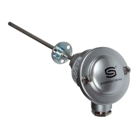
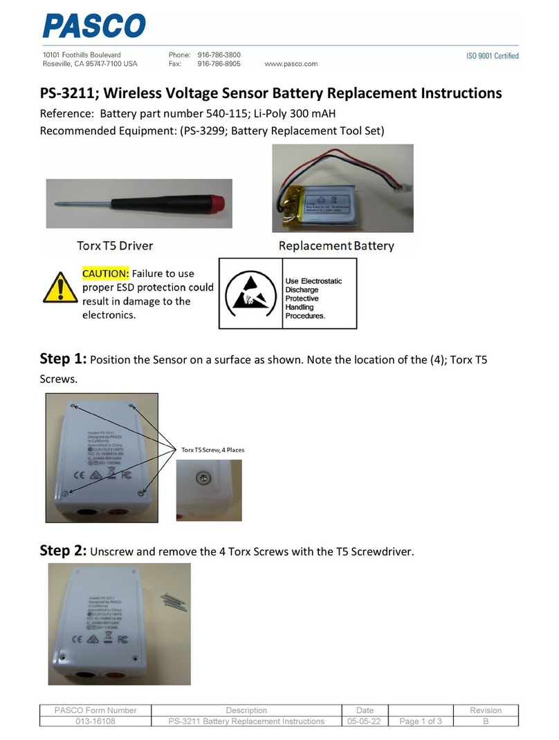
S+S Regeltechnik
S+S Regeltechnik THERMASGARD RGTM1 Series Operating Instructions, Mounting & Installation

AimSafety
AimSafety PM100 user manual
LaserLiner
LaserLiner SuperPlane-Laser 3D Pro manual
Gossen MetraWatt
Gossen MetraWatt U1281 operating instructions
Umarex
Umarex Laserliner AutoCross-Laser 2 XP operating instructions
