CPN MF-400 User manual
1
Installation Manual MF-400 IoT Satellite Bridge
Version 1.3 – Date: 22 Nov 2021
Copyright © 2020 CPN Satellite Services G bH
All rights reserved. This publication and its contents are proprietary CPN Satellite Services G bH. No part
of this publication ay be reproduced in any for or by any eans without the written per ission of
CPN Satellite Services G bH, Adalbert-Stifter-Str. 15, 65375 Oestrich-Winkel, Ger any.
CPN Satellite Services G bH has ade every effort to ensure the correctness and co pleteness of the
aterial in this docu ent CPN Satellite Services G bH shall not be liable for errors contained herein. The
infor ation in this docu ent is subject to change without notice. CPN Satellite Services G bH akes no
warranty of any kind with regard to this aterial, including, but not li ited to, the i plied warranties of
erchantability and fitness for a particular purpose.
Trade arks
CPN Enclosure are trade arks of CPN Satellite Services G bH. All other trade arks are the property of
their respective owners.

2
Contents
Preli inary note ............................................................................................................................ 3
Safety Instructions ........................................................................................................................ 3
Ter inology and Abbreviations .................................................................................................. 3
Required Tools ............................................................................................................................... 3
Technical overview ....................................................................................................................... 4
1.
Mount the CPN Enclosure to the pole ................................................................................ 5
2.
Mount the solar panel to the pole ....................................................................................... 6
3.
Mount the antenna to the pole ............................................................................................ 7
4.
Mount the IDP-Ter inal to the pole ................................................................................... 8
5.
Open the CPN Enclosure ...................................................................................................... 9
6.
Ensure all circuit breakers are switched off / not plugged in ....................................... 10
7.
Re ove the top of the battery- ount ............................................................................. 11
8.
Insert the battery into the Enclosure ............................................................................... 12
9.
Connect the battery to the Enclosure ............................................................................... 13
10.
Connect the solar panel cables to the Enclosure ............................................................ 14
11.
Connect both sides of the solar panel .............................................................................. 15
12.
Insert the cable of the IDP and connect it ...................................................................... 16
13.
Insert the antenna cable and connect it .......................................................................... 17
14.
Switch on / plug in all circuit breakers inside the Enclosure ........................................ 18
15.
Check if the syste is operating properly ....................................................................... 19
16.
Close the CPN Enclosure .................................................................................................... 20
Any questions or suggestions? ................................................................................................. 21
3
Preli inary note
Please read anuals of the installed syste s to ake sure that all safety require ents are fulfilled at any
ti e.
Safety Instructions
An external fuse or circuit breaker ( ax. 20A) ust be provided in the onsite installation as
an interrupt facility for the Enclosure syste . – Only applicable for AC powered syste s!
WARNING Risk of electrical shock, fire, personal injury or death.
Do not use a power supply without proper grounding (Protective Earth). Use the ter inal on the
input block for earth connection. Make sure that protective earth is connected according to all
local and national codes and regulations!
Turn power off before working on the device. Protect against inadvertent re-powering.
Make sure that the wiring is correct by following all local and national codes.
Do not odify or repair the unit.
Do not open the electronic units, e.g. power supply, as high voltages are present inside.
Use caution to prevent any foreign objects fro entering into the housing.
Do not use in wet locations or in areas where oisture or condensation can be expected while
cover is not ounted.
Do not touch during power-on, and i ediately after power-off. Hot surface ay cause burns.
Ter inology and Abbreviations
PE PE is the abbreviation for Protective Earth and has the sa e eaning as the sy bol.
Earth, Ground This docu ent uses the ter “earth” which is the sa e as the U.S. ter “ground”.
T.B.D. To be defined, value or description will follow later.
AC 230V A figure displayed with the AC or DC before the value represents a no inal voltage with
standard tolerances (usually ±15%) included.
E.g.: DC 12V describes a 12V battery disregarding whether it is full (13.7V) or flat (10V)
230Vac A figure with the unit (Vac) at the end is a o entary figure without any additional
tolerances included.
50Hz vs. 60Hz As long as not otherwise stated, AC 100V and AC 230V para eters are valid at 50Hz and
AC 120V para eters are valid at 60Hz ains frequency.
ay A key word indicating flexibility of choice with no i plied preference.
shall A key word indicating a andatory require ent.
should A key word indicating flexibility of choice with a strongly preferred i ple entation.
DCE data co unication equip ent
DTE data ter inal equip ent
Required Tools
Phillips screwdriver PH3 enclosure lid
Phillips screwdriver PH2 battery
Slotted screwdriver 0.6x3.5 ter inal blocks
Wrench #8 pole ount enclosure & IDP ter inal
Wrench #10 LoRaWAN antenna
Wrench #13 solar panel
Zip ties
Wire cutter

4
Technical overview
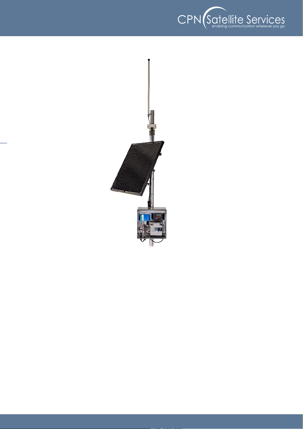
The MF 400 IoT Satellite Bridge provides network server connectivity for 100 re ote LoRaWAN™ sensors
via In arsat IsatDataPro (IDP) satellite ter inals and can operate continuously fro a single 80W solar
panel
The MF 400 runs an opti ized protocol to ensure that airti e satellite costs per sensor are kept to a
ini u . This akes the MF 400 IoT Satellite Bridge a standalone, low power, low cost solution for
adding satellite connectivity to your existing COTS LoRaWAN™ sensor devices.
The MF 400 IoT Satellite Bridge supports LoRaWAN™ version 1.0.2. The MF 400 IoT Satellite Bridge is
co patible with a very wide range of co ercial off the shelf (COTS) LoRaWAN™ sensors.
Both the co unication device and the solar charger are installed in IP67 rated CPN enclosures for harsh
environ ents.
5
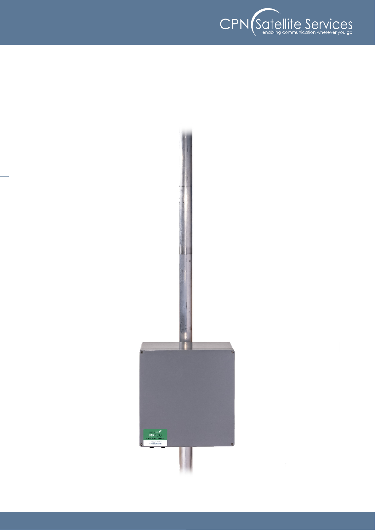
1. Mount the CPN Enclosure to the pole
Mount the Enclosure to the pole by using the pole ount located at the backside of the Enclosure.
6
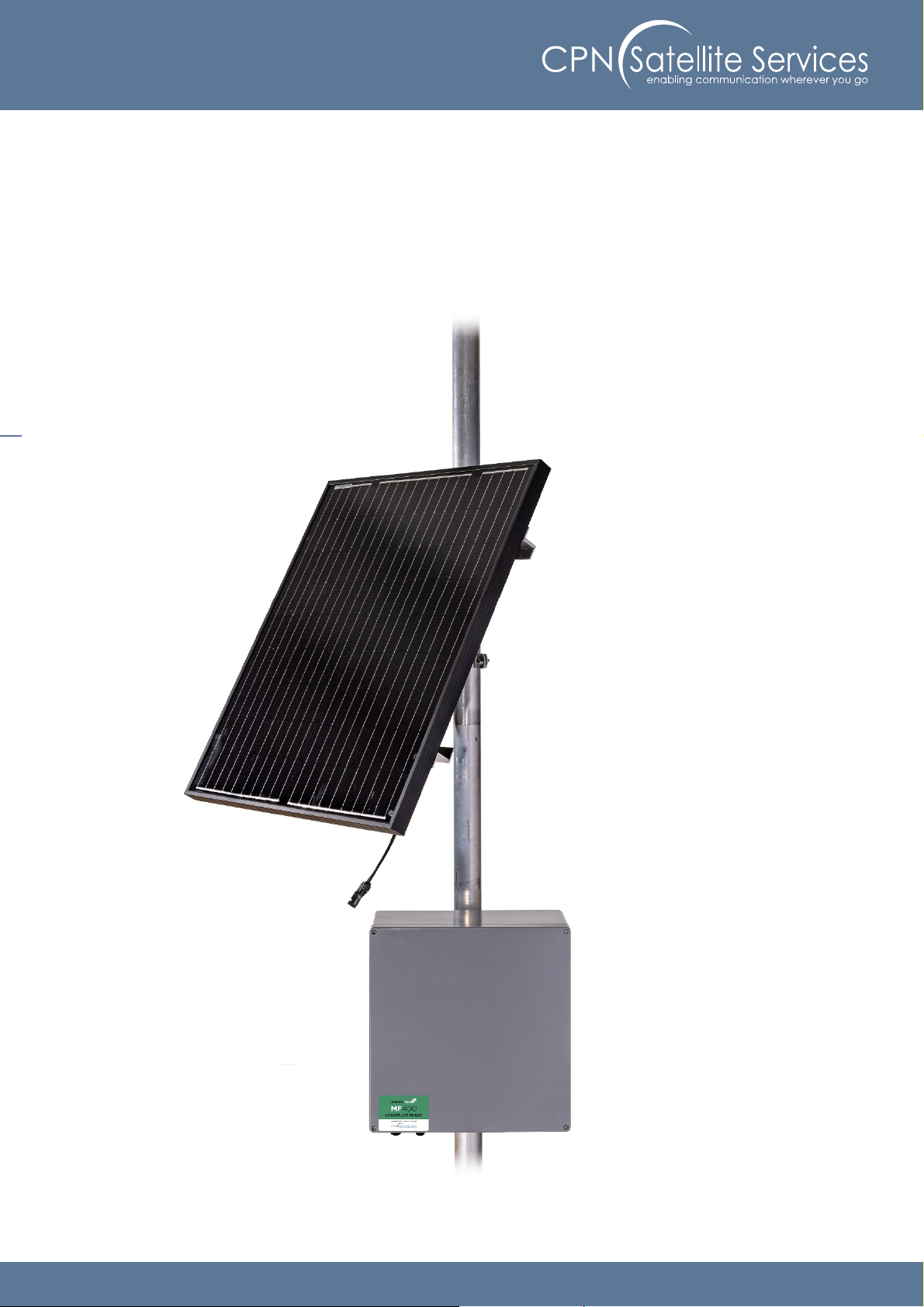
2. Mount the solar panel to the pole
Mount the solar panel to the pole by using the pole ount located on the backside of the solar panel.
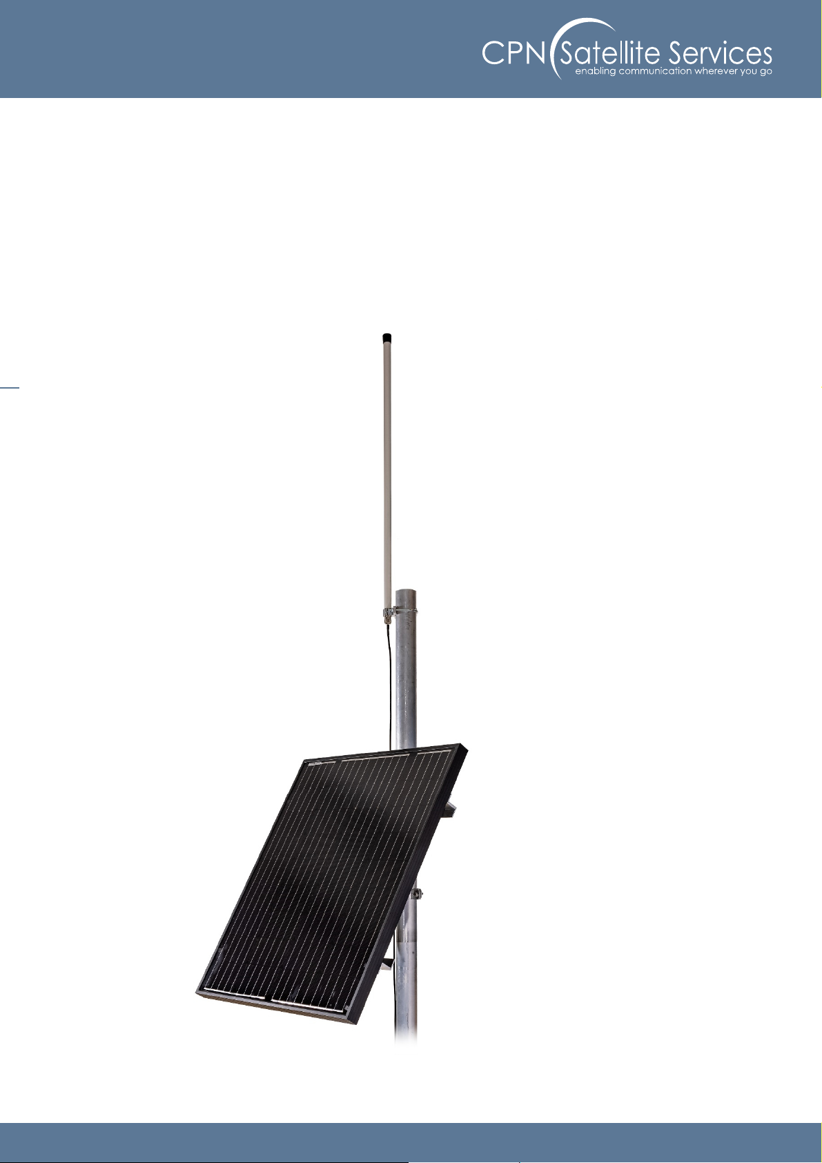
7
3. Mount the antenna to the pole
Plug the antenna cable into the antenna and use its pole ount to secure it onto the top of the pole.
Please ake sure that your installation atches antenna cable require ents!
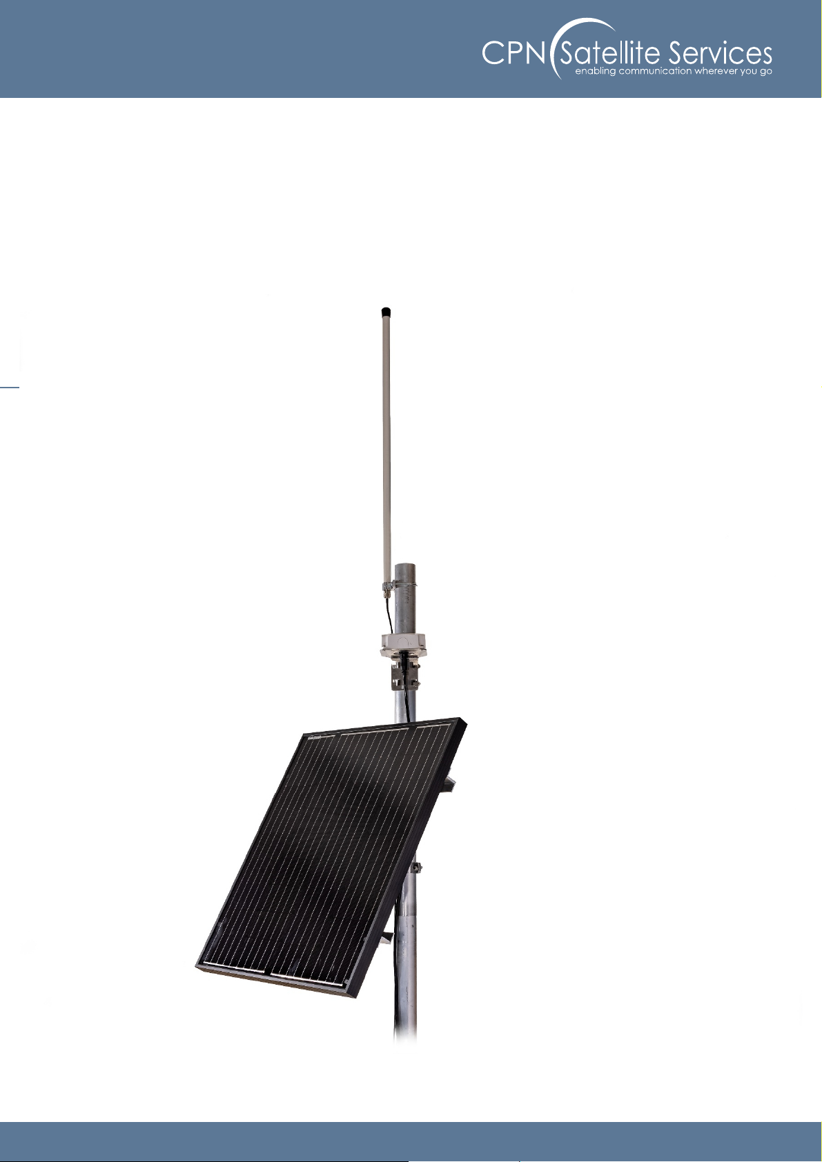
8
4. Mount the IDP-Ter inal to the pole
Plug the IDP cable into the IDP ter inal and use its pole ount to secure it onto the Pole.
We reco end using zip ties to fix the cables to the pole.
Please ake sure that your installation atches cable require ents!

9
5. Open the CPN Enclosure
Loosen the 4 arked screws of the cover and re ove it fro the Enclosure
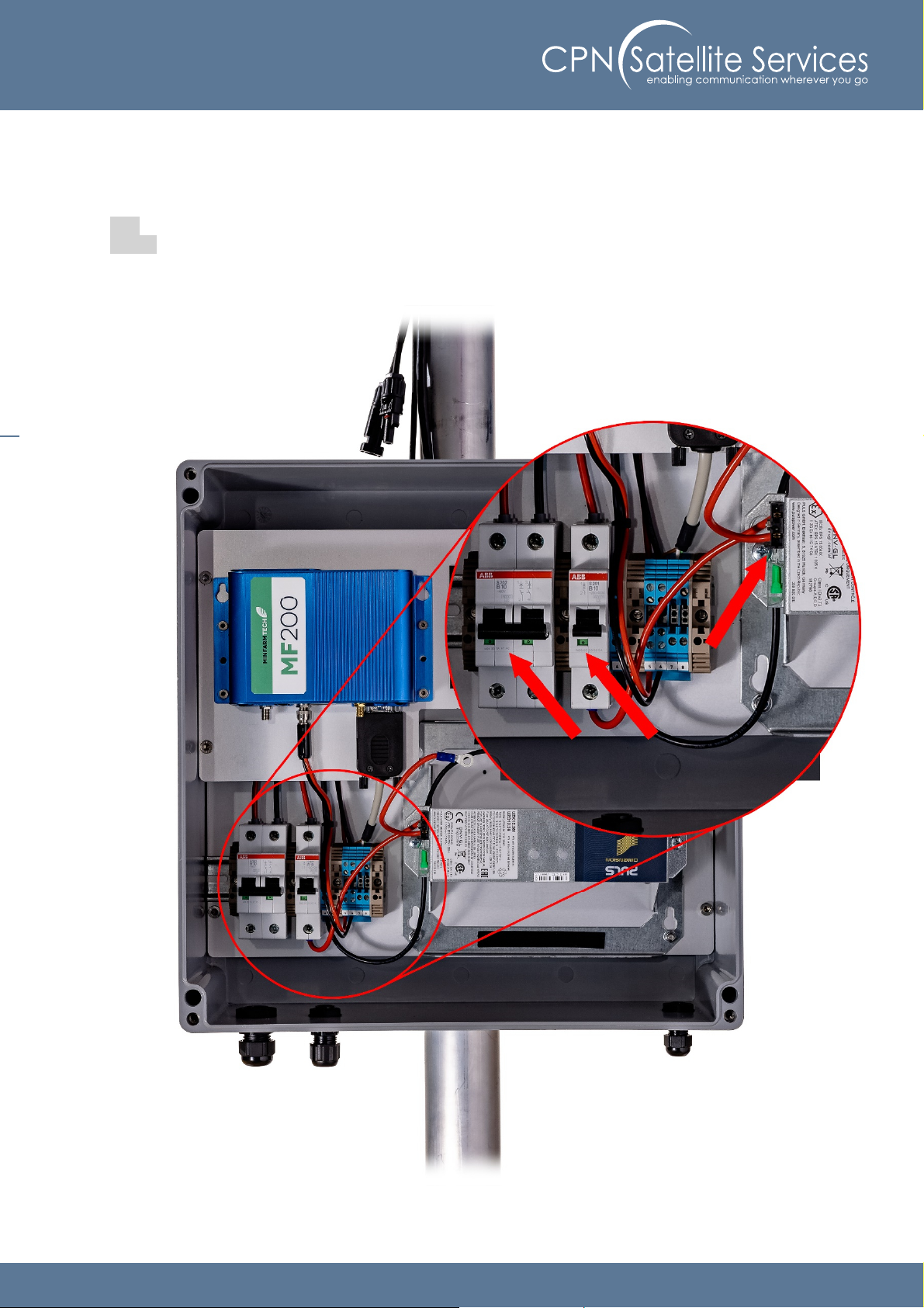
10
6. Ensure all circuit breakers are switched off / not plugged in
Make sure all circuit breakers are switched off and pointing down. Ensure that there is no fuse plugged
into the battery ount.
Red = On
Green = Off
11
7. Re ove the top of the battery- ount
Re ove the top cover of the battery ount by loosening the 2 arked screws.
Make sure that all circuit breakers are switched to OFF during installation!

12
8. Insert the battery into the Enclosure
Insert the battery into the Enclosure and reinstall the top cover of the battery ount using the 2 arked
screws.
Make sure that all circuit breakers are switched to OFF during installation!
13
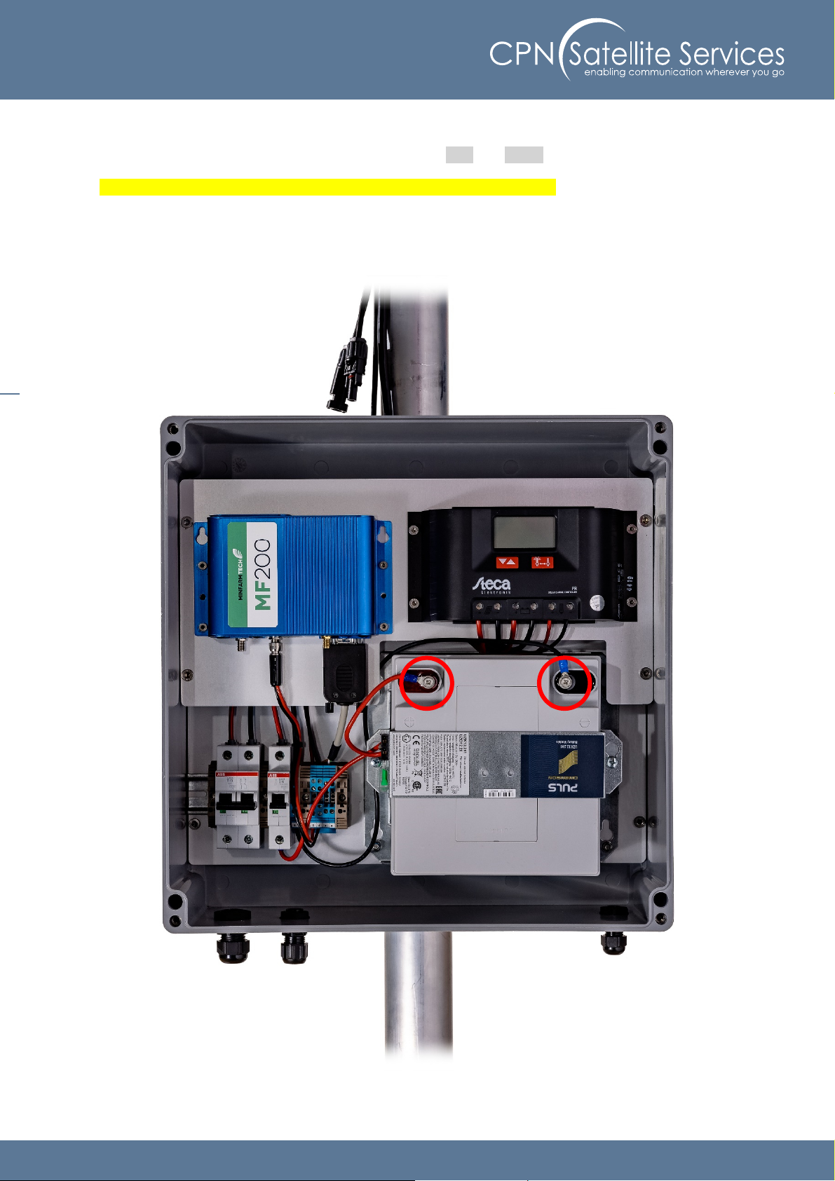
9. Connect the battery to the Enclosure
Connect the battery to the Enclosure by connecting the Red and Black wires as shown below.
Make sure that all circuit breakers are switched to OFF during installation!

14
10. Connect the solar panel cables to the Enclosure
Insert the solar panel cable into the Enclosure and connect the to the double circuit breakers inside the
Enclosure. The Red arked cable (positive pole (+)) has to be connected to the left side of the double
circuit breaker (+), the Black arked cable (negative pole (-)) to the right side of the double circuit
breaker (-).
Make sure that all circuit breakers are switched to OFF during installation!
15
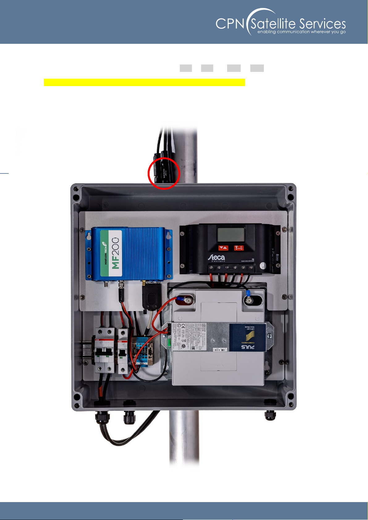
11. Connect both sides of the solar panel
Plug both sides of the solar panel cable together. Red to Red and Blue to Blue.
Make sure that all circuit breakers are switched to OFF during installation!
16
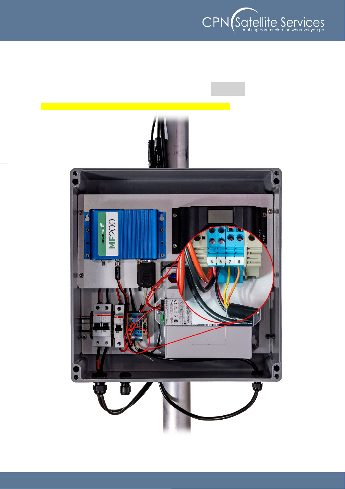
12. Insert the cable of the IDP and connect it
Insert the cable co ing fro the IDP ter inal (DCE) into the Enclosure and connect it to the ter inal
blocks arked fro #5 to #8. Connect the wires as following:
#5 #6 # #8
ST-6100 Red (+ PWR)
Black (- GND)
Yellow (RX)
Orange (TX)
ST-2100 Grey (+ PWR) Brown (- GND) Yellow (RX) Green (TX)
Make sure that all circuit breakers are switched to OFF during installation!
17
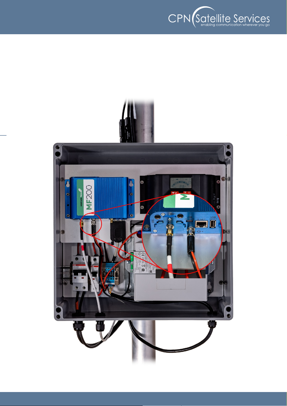
13. Insert the antenna cable and connect it
Insert the antenna cable into Enclosure and connect to the connector located on the botto left of the
MF 200 (RF).
(depending on the cable you ight need to use an SMA adapter)

18
14. Switch on / plug in all circuit breakers inside the Enclosure
Switch on all circuit breakers and plug in the fuse that goes into the battery ount.

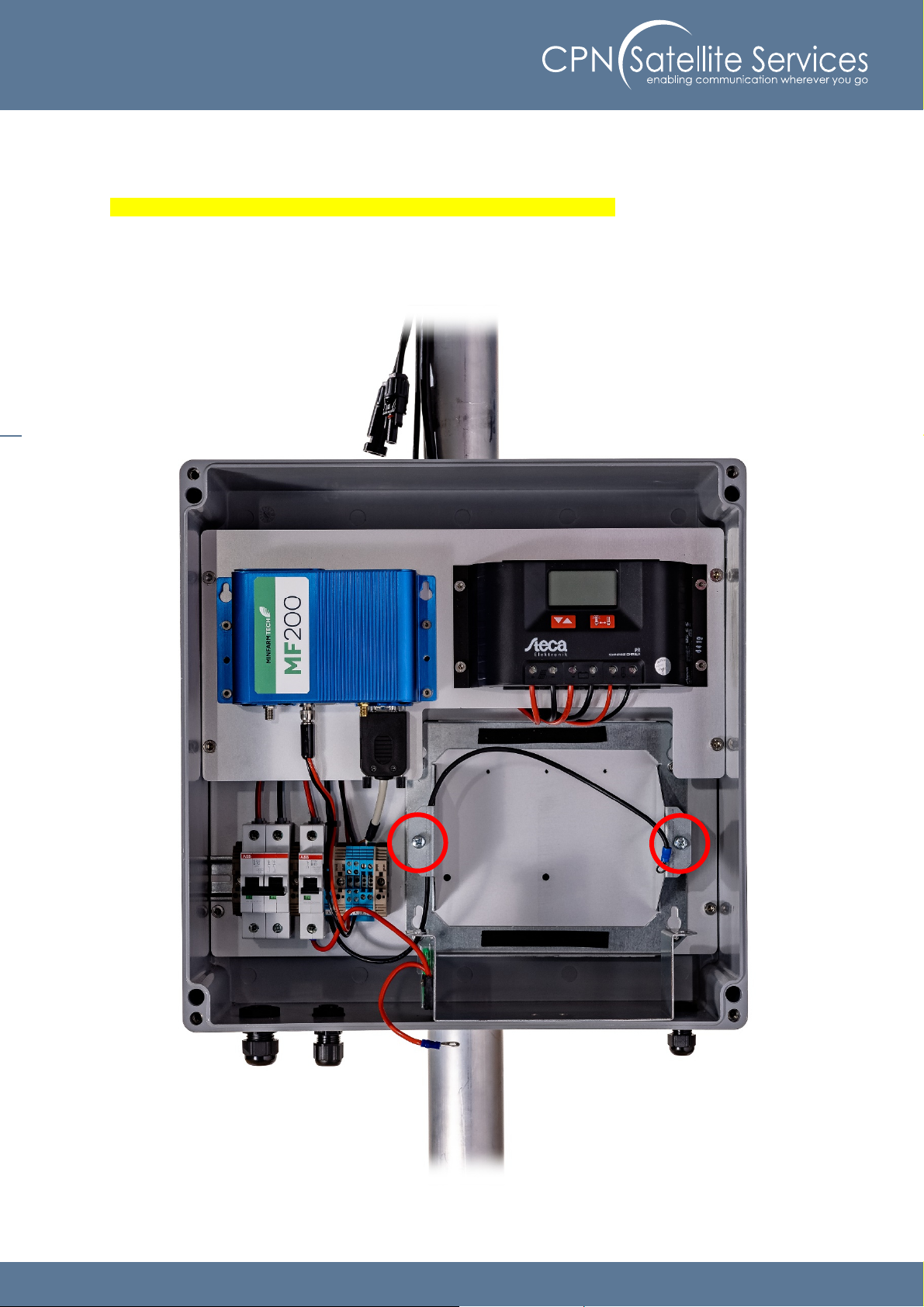
19
15. Check if the syste is operating properly
Make sure the solar panel is connected and the batteries are charging.
Please ensure that all cable glands are tightened to get the IP-67 rating and the strain relive for the
cables.

20
16. Close the CPN Enclosure
Screw in the 4 arked screws of the cover to reinstall it to the Enclosure.
Table of contents
Other CPN Network Hardware manuals


 Specification sheet")