CPT AUTOPILOT Wheel Pilot User manual

OPERATION MANUAL
·
Operation
·
Dockside checkout
·
Sea trials
·
Maintenance & Troubleshooting
·
Specifications
MANUFACTURED AND SOLD DIRECT BY
CPT AUTOPILOT INC.
7960 B Soquel Drive #114 Aptos CA 95003 USA
www.cptautopilot.com email: info@cptautopilot.com

OPERATION OF THE CPT AUTOPILOT
The CPT is an extra crew member to man the wheel, day or night, rain or shine. It is amazing
to take your hands off the wheel and experience the freedom the CPT provides.
WARNING!
Always remember to maintain a proper look-out
Do not use the CPT in traffi or in waters where navigation is restri ted!
An autopilot is NOT a substitute for good seamanship. Always maintain a permanent wat h by the helm.
I TER ATIO AL REGULATIO S FOR PREVE TI G COLLISIO S AT SEA, 1972 (72 COLREGS)
Part B - Steering and Sailing Rules
Section 1 - Conduct of Vessels in any Condition of Visibility
Rule 5 - Lookout
Every vessel shall at all times maintain a proper look-out by sight and hearing as well as by all available means
appropriate in the prevailing circumstances and conditions so as to make a full appraisal of the situation and risk of
collision.
WARNING!
KEEP CHILDREN AND PETS
AWAY FROM THE AUTOPILOT BELT
Version: 24
Updated: August, 2018
Applies to autopilots manufactured after Feb, 2018
(Serial numbers 100822 and higher)
MANUFACTURED AND SOLD DIRECT BY
CPT AUTOPILOT INC.
7960 Soquel Drive, #B114, Aptos, CA 95003 USA
Website:
.cptautopilot.com
Email:
PAGE 2 OF 21
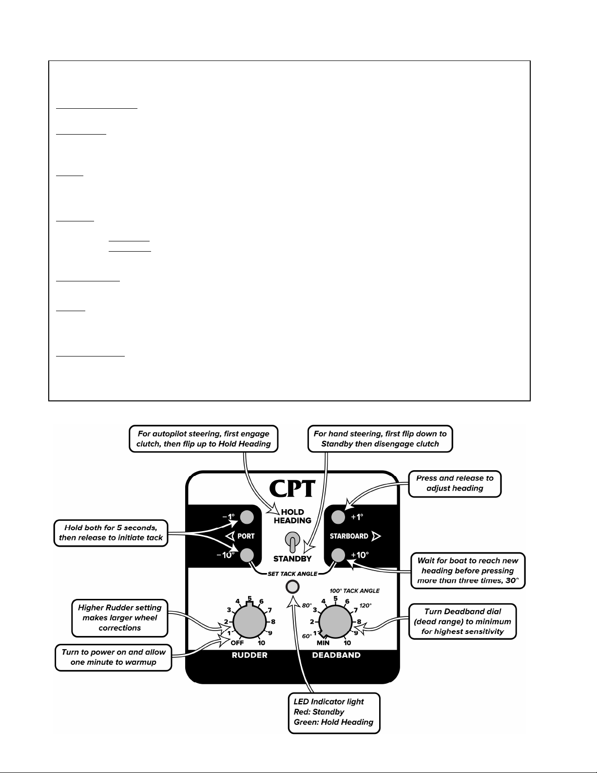
CPT Operation
Turn po er on ith Rudder control. Wait at least 1 minute for pilot to arm up before using.
To Steer with Autopilot:
Hold boat on desired heading 30 seconds. Engage Clutch. Flip toggle-s itch up to Hold Heading. Fine tune Rudder and Deadband as needed.
To Hand steer:
Flip toggle-s itch do n to Standby and Disengage Clutch
* In an emergency, the heel can be forced to overpo er the clutch and shear the shear-pins
Rudder: Controls autopilot Rudder Response
Determines proportionally ho far to turn heel for heading corrections.
High settings turn boat’s rudder more; Lo settings turn boat’s rudder less
Turn to 5 at start, then increase or decrease as needed. Set as high as possible ithout causing over-steering
Deadband: Controls autopilot “Dead Range”
Determines “sensitivity” to boat heading changes. Use to adjust for sea conditions.
Lo settings hold boat to a tighter heading Lo est setting allo s approximately ±1° heading range
High settings allo the boat to steer ithin a ider heading range Setting of “5” allo s approximately ±10° heading range
Turn to minimum at start. Increase only after rudder control is set and autopilot is steering adequately
°and 0° buttons: Push and release buttons to adjust heading; changes target heading
Check boat head ay and rudder/deadband if boat is not responding (1° button ill not be immediate)
Tacking: Simultaneously hold do n the 1° and 10° buttons for the direction you ish to tack. Keep both buttons pressed for five
seconds. Release buttons to tack. Set deadband lo to keep the boat close to the ne tack heading.
* Flip to Standby and disengage clutch if stuck in irons or no ind to prevent heel hitting rudder-stops
Change Tack Angle: Hold both 10° Port and 10° Starboard buttons do n at the same time. Turn deadband dial to ne tack angle and
release buttons to set. Remember to return deadband dial to desired deadband setting after ards.
* Tack angles are approximate and ill vary from boat to boat based on the magnetic environment. You ill have to
see hich angle orks best for your boat.

CPT Autopilot Operation Manual
© 2018 CPT AUTOPILOT INC. VERSION 22 PAGE 3 OF 21
OVERVIEW OF AUTOPILOT OPERATIO ................................................................................................................................. 4
A. Setting Rudder and Deadband controls...................................................................................................................................4
B. Magnetic Headings......................................................................................................................................................................4
AUTOPILOT CO TROLS.................................................................................................................................................................. 4
Autopilot Steering ............................................................................................................................................................................4
Hand Steering ...................................................................................................................................................................................4
Hold Heading / Standby Toggle.....................................................................................................................................................4
1° and 10° Buttons............................................................................................................................................................................5
Tacking ..............................................................................................................................................................................................5
Adjusting the Tack Angle........................................................................................................................................................... 5
Rudder Control.................................................................................................................................................................................6
Deadband Control............................................................................................................................................................................7
Control Summary.............................................................................................................................................................................7
Changing the Motor Rotation ........................................................................................................................................................7
Setting the Magnetic Reference......................................................................................................................................................8
Calibrating the Autopilot Compass Magnetic Sensors...............................................................................................................9
SAIL TRIM ...........................................................................................................................................................................................10
A. Boat Balance...............................................................................................................................................................................10
B. Beating.........................................................................................................................................................................................10
C. Running ......................................................................................................................................................................................10
D. Reaching .....................................................................................................................................................................................11
APPE DIX........................................................................................................................................................................................... 12
Dockside Checkout ........................................................................................................................................................................12
Keeping Watch ...............................................................................................................................................................................13
Sea Trials..........................................................................................................................................................................................13
Maintenance and Adjustments ....................................................................................................................................................15
General Maintenance and Storage.......................................................................................................................................... 15
Belt Tension ............................................................................................................................................................................... 15
Pulley and Clutch Maintenance.............................................................................................................................................. 15
Shear Pin Clearance Adjustment and Clutch Maintenance................................................................................................16
Connector Maintenance........................................................................................................................................................... 16
Connector Maintenance........................................................................................................................................................... 17
Wheel Pulley ..............................................................................................................................................................................17
Factory Service........................................................................................................................................................................... 17
Troubleshooting .............................................................................................................................................................................17
TECH ICAL SPECIFICATIO S ....................................................................................................................................................21
LIMITED WARRA TY.....................................................................................................................................................................21

PAGE 4 OF 21
OVERVIEW OF AUTOPILOT OPERATION
The rudder control and deadband control must be set properly for the CPT to hold heading. Tack angles are
approximate and will vary from boat to boat based on the magnetic environment and deadband setting, you
will have to see which angle works best for your boat.
A. Setting Rudder and Deadband controls
The Rudder dial should be set high enough so that when the boat falls off it is brought back to heading with
just one or two “pulses” or wheel corrections. If the pilot makes repeated pulses or wheel corrections in one
direction the rudder control is set too low; the setting needs to be raised. If the pilot oversteers, lower the
setting a bit. High rudder settings provide larger rudder corrections, low rudder settings provide smaller
rudder corrections. The boat must be balanced and respond to the rudder in a consistent manner, as the
rudder dial sets the rudder response for one consistent response.
Start with the Deadband dial (dead range) set to minimum, especially when first using the pilot. If the pilot is
making port and starboard corrections too frequently, or reacting to swell, gradually raise the deadband setting
so that corrections are made when needed but are not constant. Low
deadband settings provides more sensitivity to heading changes, high
deadband settings provide less sensitivity when in swells and seas. A
deadband of 5 allows the boat to range approximately ±10° to port or
starboard.
The CPT's performance can be improved by careful tuning but continously
adjusting the controls is not necessary. Once you find the rudder and
deadband settings that work best for your boat, you'll use the same settings
most of the time.
B. Magnetic Headings
The CPT keeps a vessel pointing to a magnetic heading; this is not the same
as a GPS course. In keeping to a compass heading, your vessel will point the
same direction but still be subject to drift from wind and currents. This drift
will be apparent when observing your GPS over time, and periodic heading
adjustments will easily keep the vessel on your waypoint course.
AUTOPILOT CONTROLS
Autopilot Steering
1. Disengage clutch, flip toggle to Standby. Turn power on with Rudder control. Allow one minute to warmup.
2. Hold boat on heading for at least 30 seconds. Engage clutch. Flip toggle switch to Hold Heading.
3. Adjust Rudder and Deadband controls to suit conditions
Hand Steering
1. Flip toggle switch to Standby.
2. Relieve pressure from wheel and disengage clutch (grasp the black disk on clutch and pull outward ¼")
Hold Heading / Standby Toggle
After a 1 minute warm up, flipping the switch to Hold Heading sets the pilot to the boat’s heading.
GPS
Course
Waypoint
Waypoint
Direction of current
Compass
Course

CPT Autopilot Operation Manual
© 2018 CPT AUTOPILOT INC. VERSION 22 PAGE 5 OF 21
Hold the boat steady on desired heading about 30 seconds, engage clutch, then flip to Hold Heading. Keeping
the boat on heading for a longer period before flipping to Hold Heading will allow the pilot to match your
heading more closely.
When toggled to Standby, the pilot is on standby and the motor will not turn. The clutch can now be
disengaged for hand steering.
During the warm-up period the sensor heading will drift. Allow at least 1 minute for the pilot to warm-up
before flipping to Hold Heading, otherwise pilot will respond to drift and correct in one direction once/second
when more than 5-degrees from boat’s heading.
1° and 10° Buttons
The push-buttons allow you to alter the target heading in 1° and 10° increments. The target heading is altered
when the button is released. Pressing and releasing once alters the target heading once, pressing and releasing
twice alters the target heading twice, pressing and releasing three times alters the target heading three times,
etc. The deadband setting will affect how close the boat stays to the target heading. Due to differences between
boats, heading adjustments are not exact; check your ship’s compass after settling on the new heading.
It is easy to lose track when pressing buttons multiple times, and you may overshoot the desired heading if the
boat is slow to respond due to currents or conditions. In these cases flip to Standby and then back to Hold
Heading when the desired heading is reached or flip to Standby and steer to the new heading manually.
A note about the 1° button response:
When you push the 1° button, the new target heading will change by one degree, but you will not see an
immediate motor response until the boat strays out of the deadband range. The tightest course-holding is
when the deadband is set to the lowest setting (min), which allows a “dead-range” of about two degrees. If the
bow of the boat strays more than about one degree port or starboard the pilot will take corrective action with
the 1° button; when the boat is within that range there will be no immediate motor response.
Tacking
Tack angles are approximate and will vary from boat to boat based on the magnetic environment and rudder
response. You will have to see which angle works best for your boat. In general, point as high as you can while
keeping good boat speed before tacking. Set deadband low to keep the boat close to the new tack heading.
Simultaneously hold down the 1° and 10° buttons for the direction you wish to tack. Keep both buttons pressed
for five seconds. Release buttons to tack.
Port Tack: Simultaneously press Port 1° and 10° for five seconds and release.
Starboard Tack: Simultaneously press Starboard 1° and 10° for five seconds and release
The rudder control must be properly set and the boat must have adequate speed and rudder response for the
tacking feature to work correctly. Keep an eye on boat response to avoid hitting the rudder stops; flip to
Standby and hand steer if boat does not respond to the tack well or gets caught in irons. Making inadequate
headway, pointing too high, or having unbalanced sails can cause the boat to lose speed and have poor
response to the rudder—go to Standby and disengage the clutch to avoid hitting rudder-stops. If the boat is not
tacking far enough, the tack angle can be increased; if tacking too far the tack angle can be decreased.
Depending on the conditions and the boat’s momentum, the boat may carry slightly past the tack before
correcting to the final heading.
Adjusting the Tack Angle
The autopilot comes from the factory with the Tack Angle set to 100°. The deadband dial shows Tack Angle
settings from 60°-120°. Turn the deadband dial to the desired tack angle. Hold the 10° Port and 10° Starboard
buttons down simultaneously for two seconds then release them. Remember to return the deadband dial to
desired deadband setting afterwards.

PAGE 6 OF 21
Rudder Control
The Rudder control turns the autopilot on, and determines how far the boat’s wheel (and rudder) turns when a
heading correction is needed; the response is the same for both port and starboard corrections and will not
work well with play in the steering system. Low settings result in smaller wheel corrections, higher settings in
larger wheel corrections. The corrections are proportional to the amount of heading change needed. The best
rudder setting will be high enough to return the vessel to heading with just one or two motor pulses or
orre tions. If the pilot responds with many smaller repeated corrections in one direction, raise the rudder
setting.
The rudder control performs like a helmsman in a fog who can only see the compass. If this helmsman is told
to move the wheel exactly one inch for each five° heading error, he will do exactly that every time a correction
is needed. If these motions result in under-control and sluggish corrections, you can tell him to move the
wheel further for a given correction.
The boat must be balanced for consistent steering, it must respond to the rudder in a consistent manner; the
rudder dial sets the rudder response for one consistent response. It will not adjust for sloppy or excessive play
in a boat’s steering system.
The rudder control is used to match the CPT’s response to your boat's steering needs. Some boats take many
turns of the wheel to move the rudder, while others take only a few. The rudder control can adjust for this.
Every boat also responds somewhat differently to the rudder. Generally full keel boats with more turns lock-
to-lock take a higher rudder setting, but this rule does not always follow for some spade-rudder boats.
If the rudder control is set too high for your boat, the wheel will turn too far; the boat will over-steer too far
port and starboard. Lower the rudder setting.
The most common mistake seems to be setting the rudder setting too low. If the rudder control is set too low,
the autopilot will make many small repeated corrections in one direction to return to the desired heading, and
will spend a lot of time on one side of the rhumb line. The boat may gradually fall off and the pilot will not
keep the boat on heading. Almost all boats require a rudder setting of 4 or higher.
Either of these actions is relatively easy to identify and, with some experimentation underway, you should be
able to find the correct setting for your boat. A rudder setting that works while sailing in lighter winds may
have to be raised when winds increase.
A boat may require a slightly higher rudder setting at low speeds than at higher speeds. A sailboat may require
a higher setting when running than when beating and a higher setting when sailing than when motoring.
Full Keel Boats: A full keel boat with 3-4 turns lock-to-lock will typically use a rudder setting of 5-6.
Fin Keels and Spade Rudders: Response to the wheel may be more sensitive. The rudder setting will depend on
the boat’s response to the rudder, and you will need to see what setting works best. It may take more balancing
and de-tuning for steady steering and keeping the boat from reacting to every gust or condition. With
increased speed downwind, response to the rudder increases, and lowering the rudder setting slightly works
well. If the boat is easily under-steered, over-steered, or has wheel play, the rudder setting may be a
compromise between the two.
If you are becalmed, stuck in irons or not making headway, disengage the CPT. The CPT will continue to try
and make heading corrections, but the vessel will not respond to rudder changes. If left unattended the rudder
could eventually hit the rudder stops.
(Avoid hitting the rudder stops; if it occurs a looser belt provides some give and you will hear a warning thump
as the belt jumps in its cogs; but if the belt is over-tensioned or used with a tensioner it eliminates any give in
the system and the shear pins are designed to shear if the belt doesn’t jump)

CPT Autopilot Operation Manual
© 2018 CPT AUTOPILOT INC. VERSION 22 PAGE 7 OF 21
Deadband Control
The deadband dial determines how far the vessel can stray from heading before a correction is made (dead
range). In a proportional pilot, there is always some deadband inside which the pilot does not activate. If this
deadband is small, (1°-2°) the pilot will continuously run port or starboard making course corrections. In a
seaway, a boat will yaw back and forth along the desired course as it makes its way over the waves, but
generally it has enough directional stability to keep a fairly good average heading. An adjustable deadband
permits the boat to work its way through the waves without continuously using the rudder to try to fight the
natural weaving and movement of the hull.
The deadband setting is adjusted with the deadband dial. Start out with the deadband set to minimum when
first using the CPT. Turning the dial clockwise increases the deadband. Most boats steer well at settings of 2-3
in swells, with lower settings in flat water. On long passages, turning the deadband and rudder up a bit higher
can reduce battery use while still providing a good average course. A deadband of “5” will allow the boat to
range about 10° to port or starboard of the target heading; the pilot will make a correction if the boat strays
more than 10° to port or starboard. When the boat’s heading is within the deadband range, small heading
adjustments made with the 1° button will change the target heading but not take immediate effect until the
boat’s heading is outside the deadband range. The lowest deadband setting allows the boat to range about 1° to
port or starboard of the target heading, depending on the boat’s response to the rudder.
Rhythmic CPT steering corrections, in time with the roll of the boat, indicate that the deadband may be too
low. The deadband can be increased slightly to avoid constant correction. A low deadband does not always
mean that the boat will maintain a straighter course; it can cause the pilot to over steer if the rudder setting is
too high. In rougher seas, the deadband should be higher to avoid constant corrections. A lower deadband
setting is generally beneficial when sailing downwind or in flat water. Lower deadband settings cause higher
sensitivity to heading changes; higher deadband settings cause lower sensitivity to heading changes.
Most of the CPT's steering action should be periodic corrections. Raise the deadband a bit to avoid excessive
battery drain and wear on the CPT.
Control Summary
The Rudder control determines how far the wheel should be turned when corrections are needed. The
Deadband control determines when a correction is needed—sensitivity to heading changes and seas or “dead
range”.
Changing the Motor Rotation
The motor rotation is preset at the factory for your installation but can be easily changed and re-set from the
control box.
Standard Rotation: Drive Pulley Facing Forward
1. Turn the CPT OFF (turn the Rudder control fully counter-clockwise). While off, push and hold the
Starboard 1° and 10° buttons and the Port 10° button; hold all three buttons down at the same time.
2. Turn the pilot on while holding the three buttons down.
3. Release the buttons after five seconds.
4. If successful, the LED on the control box will blink red eight times.
Reverse Rotation: Drive Pulley Facing Aft
1. Turn the CPT OFF (turn the Rudder control fully counter-clockwise). While off, push and hold the
Port 1° and 10° buttons and the Starboard 10° button; hold all three buttons down at the same time.
2. Turn the pilot on while holding the three buttons down.
3. Release the buttons after five seconds.
4. If successful, the LED on the control box will blink red eight times.
PAGE 8 OF 21
Setting the Magnetic Reference
Setting the magnetic reference aligns the autopilot compass to the local magnetic
inclination (dip angle).
The autopilot comes from the factory set for the magnetic field inclination in
California. If you are located significantly farther north or south, the magnetic
reference should be set again on location. Magnetic field inclination differences will
usually only start to become noticable if you are located below 15-degrees orth or
above 55-degrees orth.
·
This procedure is best performed at the dock in flat water.
·
If at sea, only perform this procedure in calm seas while holding the control box to stabilize it. If the
vessel is moving, maintain a steady heading during the procedure.
·
If the control box is not kept level or is bumped during this procedure, the reference may be skewed
resulting in poor autopilot performance.
·
Make sure that power to the autopilot is not interrupted during the procedure and in the 15 seconds
following the procedure.
Steps:
1. Turn on the autopilot and set the Rudder dial to 5.
2. Leave the autopilot on for 10 minutes or more to allow the temperature inside the control box to
stabilize.
3. Turn the Rudder dial to OFF and remove the control box from its bracket.
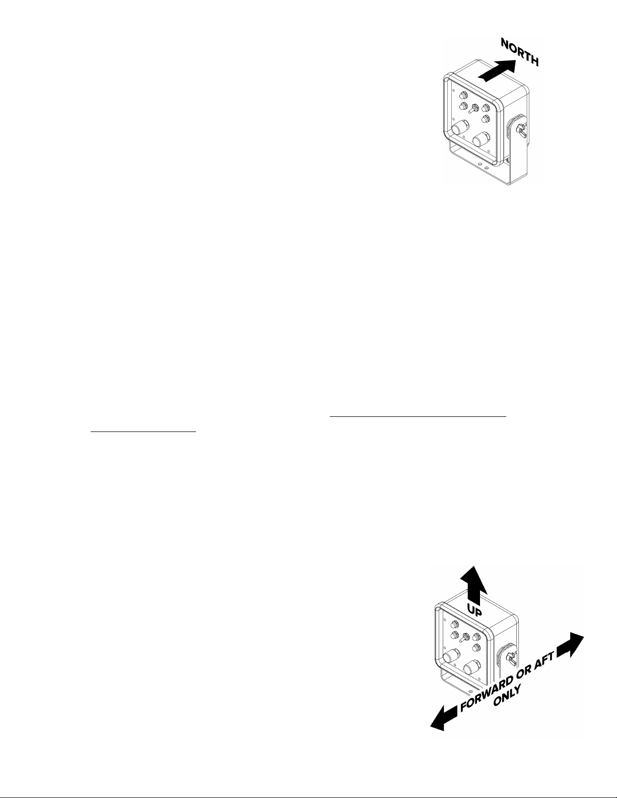
4. Hold the control box so that it is pointed approximately due orth and so the top is level and steady;
hold it shoulder-height or rest it on a cockpit seat, but keep it away from metal objects and any
possible magnetic fields. The center of the cockpit, about shoulder high is usually free from magnetic
fields on most boats. If resting on a surface, make sure there are no metal fasteners nearby or metal
equipment underneath.
5. While holding the control box steady, simultaneously press and hold both the Port 1° and Starboard 1°
buttons then turn the Rudder dial on (past 1). Continue holding the buttons. The light will blink red 5
times and then remain solid: you can now release the buttons.
6. Wait 15 seconds more. Do not turn off power to the autopilot before 15 seconds have passed.
The Magnetic Reference is now set in memory and only needs to be set again if you move to a region with a
significantly different magnetic inclination or recalibrate the autopilot compass magnetic sensors.
Control Box Orientation Restrictions
The control box must be oriented level and facing either the bow or the stern of
the boat. The cable exits the bottom side of the box. If the control box does not
face the bow or stern of the boat, the autopilot heading will be affected by the boat
pitching and heeling.

CPT Autopilot Operation Manual
© 2018 CPT AUTOPILOT INC. VERSION 22 PAGE 9 OF 21
Calibrating the Autopilot Compass Magnetic Sensors
The magnetic sensors in the autopilot compass are calibrated in California to account for variations in the
individual sensors. In most cases this calibration is sufficient, however in some geographic locations the
magnetic field is significantly weaker (than in California) and the compass may need to be recalibrated on
location. Performing the magnetic calibration procedure will recalibrate the autopilot compass to the local
magnetic field strength. Do not calibrate the compass as a routine trouble-shooting measure. If the autopilot is
not steering well, first check for magnetic interference. Calibration will not correct for magnetic interference
near the control box.
·
This procedure must be performed in a magnetically clean environment. Stand several feet away from
any source of magnetism and at least six feet away from a steel hull or similar. Remove any
steel/magnetic items from your person. Any magnetic interference will skew the calibration results
and impair autopilot performance. Sources of magnetism include:
The autopilot motor
Batteries
peakers
teel or metal objects
Current carrying wires
LCD screens
Mobile phones
·
The magnetic reference must be re-set after the compass is calibrated.
·
Make sure that power to the autopilot is not interrupted during the procedure.
Steps:
7. Set the toggle switch to STA DBY. Turn O the autopilot (set the Rudder dial to 5). Leave the autopilot
on for 15 minutes or more to allow the temperature inside the control box to stabilize.
8. After at least 15 minutes have elapsed, turn the Rudder dial to OFF and remove the control box from its
bracket.
9. Comfortably hold the control box, keeping it away from metal objects and any possible magnetic fields.
The center of the cockpit, about shoulder high is usually free from magnetic fields on
most boats.
10. Simultaneously press and hold both the Port 10° and Starboard 10° buttons then turn the
Rudder dial O (past 1). Continue holding the buttons. After several seconds, the light
will BLI K GREE to indicate the calibration is in progress: you can now release the
buttons. The autopilot will gather calibration data for approximately sixty seconds. The
light will continue to blink until the calibration is complete.
11. For the next sixty seconds, rotate the control box to expose it to the magnetic field at
every angle. The speed of motion is not critical but move smoothly and not too fast. Try
to keep the control box in the same location and move your body around it (or turn it in
your hands) rather than moving it around your body.
a. Rotate the control box 360° and back to the beginning position in each axis
(roll, pitch, yaw) as shown.
b. Move the control box in figure-eight motions while turning it through all 360°
of headings.
12. When the calibration is complete, the light will change to SOLID GREE for twenty
seconds. If there was a problem with the calibration, the light will BLI K RED 25
times. The autopilot will then return to normal operation (the light will be red or
green, depending on the position of the Hold Heading toggle switch).
13. The compass is now calibrated. ext, perform the magnetic reference procedure.

PAGE 10 OF 21
SAIL TRIM
Even the best autopilot can be crippled by poor boat trim, and the rudder and deadband settings effect how
accurately the boat holds the heading.
The boat must be balanced on all points of sail and in all wind conditions for proper CPT operation.
This means that through the skipper's selection of sails, trim and heading, the boat should tend to maintain a
stable course without a significant amount of weather or lee helm. Reef and trim or head-off when wind and
sea conditions increase. The CPT is not recommended for racing.
The rudder dial manually sets the rudder response for one consistent response, there is no automatic response
for changing conditions.
When sailing, the boat should maintain adequate speed for effective rudder control; it must make enough
headway for steering to be effective. When wind and seas increase, and especially when running downwind,
quick rudder response becomes important; lowering the deadband and slightly raising the rudder control
helps with full keels, and increasing vessel speed or falling off will lessen the effect of following seas. Fin keels
may benefit from lowering the rudder setting due to increased speed and rudder efficiency. Always be aware of
the relative wind angle, and keep the boat on a course to prevent an accidental gibe. If the boat is in danger of
broaching, change heading or speed, reduce canvas, or put a competent helmsman at the wheel. Because of the
manual rudder and deadband controls, the CPT performs best when the boat is balanced for consistent
steering needs. If the wheel needs to be turned very little while going down the face of a swell, but then turned
wildly at the bottom or in gusts, the boat is not balanced for the conditions, and the pilot will not anticipate the
constantly changing steering needs.
A. Boat Balance
A balanced boat has very little or no helm, either weather or lee. A boat that is in trim and balanced does not
round up to windward at every gust. A boat with a heavy weather helm is one that has been poorly trimmed or
is carrying a poor selection of sails. The boat should be trimmed for consistent steering needs.
By spending time trimming the boat properly before engaging the CPT, you will place lower current demands
on your boat's electrical system, steer a straighter average course and create less wear-and-tear on both your
boat and your CPT. Practically any boat can be made to sail with a balanced helm for reasonable lengths of
time. You should strive for this as closely as possible before engaging the CPT.
B. Beating
Do not carry too much sail area and do not over-sheet the sails. This will create weather helm, excessive heel
and probably slow you down. If the boat has weather helm, ease the main sheet until the main is on the point
of luffing or just luffing slightly. If the boat still has significant weather helm, take in a reef on the main or slide
the traveler car to weather, while easing the sheet to put some twist in the main to allow the top of the sail to
luff. In heavy weather conditions where one sail will suffice, sail under jib alone.
In gusting conditions some boats, particularly fin keel/spade rudder boats and others with too much canvas
spread, will head up at every gust. The main should be sheeted loosely enough so that it luffs as soon as the
boat heads up. With some boats the main should be left luffing slightly when on course. This will allow the jib
to push the boat off, as drive from the main is lost. Maintain a course that will give the boat an adequate steady
speed and effective rudder control. The goal is to balance the boat, and eliminate the need to change the
steering with every gust, to keep the steering needs consistent.
C. Running
If running downwind with twin poled-out jibs: The jibs should be sheeted a little looser than would be
optimum so that if the boat tries to round up the leeward sail will spill air and the boat will return to course.

CPT Autopilot Operation Manual
© 2018 CPT AUTOPILOT INC. VERSION 22 PAGE 11 OF 21
If the main is carried, there should be a poled-out foresail on the opposite side. If conditions put the boat on
the verge of broaching, the main should be dropped, or fall-off and change to a safer course. When it gets to
surfing conditions, a competent helmsman should be in charge. Generally, at slow vessel speeds the rudder is
less efficient and requires a higher rudder-control setting; higher speeds require a lower setting. Get to know
your vessel’s characteristics; there is usually an optimum vessel speed, course through seas, and amount of
canvas that best balances the boat to meet the wind and sea conditions.
D. Reaching
Twin poled-out jibs or a main and a poled-out jib can be used up to 30° to 40° off a dead downwind course.
(See the comments above on running.)
In high winds and particularly in gusting conditions, both sails must be sheeted looser than usual, or sail area
reduced. THE MAI SHEET MUST BE EASED! If the boat still wants to head up at every gust, put a twist in
the main, reef it, or drop it.
Always rig a preventer to the boom when running or reaching in case of an accidental jibe.

PAGE 12 OF 21
APPENDIX
Dockside Checkout
The CPT is run for 24 hours at the factory before final testing, and the motor rotation direction has been
preset for your type of installation. It should steer your boat easily and require not more than an hour or so of
experimentation to become familiar with it. This dockside check should be performed after installation,
before sea trials.
A. Checking the Steering System
Play in the system (any movement not immediately reflected by movement in the boat's rudder) should be
eliminated or reduced to a minimum. All boats have some adjustment mechanism to take up slack and this
should be used to eliminate play. At the same time, inspect the system for chafing, frayed cables, or binding.
Grease as appropriate.
Hydraulic systems must be free of trapped air, use the proper fluid, and cannot have excessive wear or leakage
past the piston seals. Air bubbles, foaming, or leakage must be corrected if the CPT is to operate correctly.
Excessive valve delay in some systems may be inherent in the design.
B. Performing the Dockside Checkout
1. Install the belt on both pulleys. Disengage clutch and center the boat’s rudder. (Pull out on drive pulley).
2. Flip toggle to STA DBY on Control Box.
3. Check that 10 amp fuse or circuit-breaker is in place in the red-wire 12 volt (+) line and power is available
to the CPT.
4. For testing, turn the Rudder dial on and set to 5, turn Deadband dial to 1. Allow a minimum of 60 seconds
for the autopilot to warm up.
5. Engage clutch. Toggle to HOLD HEADI G.
The pilot should not respond very much, and will make small wheel corrections about every 10 seconds. If
corrections are made every second either inadequate warm-up time was allowed or there is magnetic
interference in the mounting location; do not attempt sea trial until corrected.
6. Push the 10° Port button once. The wheel should turn briefly to port, stop, and then begin short rotations
to port about once per second. Push the 10° Starboard button once, and the wheel should turn back to
starboard and stop. Toggle the control box back to STA DBY. If the autopilot responds differently
without a smooth return back to starboard, either inadequate warm-up time was allowed or there is
magnetic interference in the mounting location.
*After a short time the pilot will eventually make a small periodic correction every 10 seconds, this is
normal. Do not let the wheel turn until the rudder-stops are reached. Do not leave unattended. To stop the
wheel from turning: TOGGLE TO STANDBY AND DISENGAGE CLUTCH, or TURN PILOT OFF
If the wheel is turning the wrong dire tion when you push the 10° button, you an reverse the wheel
dire tion by following the dire tions for Changing the Motor Rotation on page 7.
If the wheel does not turn at all, check that the clutch is engaged, rudder at least 4, deadband at 1, and red
power wire connected to +12V. If the power wires are connected wrong there will be no response from the
controls and the pilot will not operate.
When left on Hold Heading, it is normal for the pilot to make a small correction every 10 seconds. More
frequent corrections once/second usually means the pilot was not allowed adequate warm-up time, the
boat’s heading is changing slightly, or there is magnetic interference near the control box.

CPT Autopilot Operation Manual
© 2018 CPT AUTOPILOT INC. VERSION 22 PAGE 13 OF 21
7. Toggle to STA DBY. Turn the Rudder dial to off to turn off pilot. Disengage clutch by pulling outward on
the clutch.
Warning: If left in HOLD-HEADING mode, the pilot will operate from boat movement at the do k: do
not leave unattended, always flip to standby or turn autopilot off. Do not allow the wheel to rotate to its
stops.
THIS COMPLETES THE DOCKSIDE CHECKOUT
Keeping Watch
The CPT is a helmsman who only sees the compass and not the surrounding sea and traffic. The skipper is
responsible for keeping a good watch at all times.
DO NOT ATTEMPT TO USE THE CPT IN TRAFFIC OR IN WATERS WHERE NAVIGATION IS RESTRICTED! ALWAYS
MAINTAIN A PERMANENT WATCH!
WARNING! KEEP SMALL CHILDREN AND PETS A WAY FROM THE CPT BELT!
Sea Trials
1. Choose a day with light winds and calm water. Initial trials should be at a speed of three to five knots
under power. After performing trials under power and becoming familiar with the unit, perform trials
under sail, maintaining a balanced sail plan - no excessive weather or lee helm.
2. Be sure there is plenty of room and no other traffic. The CPT should be off, clutch disengaged.
Flip the toggle to STA DBY, Rudder to 5, Deadband to lowest setting, allow 60 second warm-up.
Steer the boat on a steady heading for 30 seconds, engage the clutch, toggle to HOLD HEADI G. (You
may have to turn the wheel slightly to engage the clutch.)
The autopilot should make corrections to port and starboard to keep the boat on a straight heading. Do
not use the 1-degree or 10-degree buttons during this initial test.
The rudder-dial must be set high enough so that only one or two pulses or wheel corrections are needed to
keep the boat on heading. If over-steering occurs with a rudder dial of 5, slightly lower the setting, usually
no lower than 4. If under-steering (3 or more small repeated wheel corrections), raise the rudder control.
Keep the deadband dial set low until you find the best rudder setting and only increase the deadband to
reduce the pilot’s sensitivity in seas; a low deadband setting provides high sensitivity to heading changes
and heading adjustments from the 1° and 10° buttons.
3. Rudder/Deadband: These must be set properly for the pilot to steer. The Rudder ontrol determines how
much the rudder needs to turn to make a correction, the Deadband ontrol determines how far the vessel
can stray before a correction is made (dead range). Do not use the 1-degree or 10-degree buttons until
rudder & Deadband are properly set.
* Rudder ontrol too low: If the CPT makes repeated small orre tions in one direction, raise the
Rudder setting. The wheel will not turn enough to keep heading, and the boat may gradually fall-off.
Increase the Rudder setting until the boat responds to both port and starboard heading changes with only
one or two orre tions or pulses.
INTERNATIONAL REGULATIONS FOR PREVENTING COLLISIONS AT SEA, 1972 (72 COLREGS)
Part B - Steering and Sailing Rules
Section 1 - Conduct of Vessels in any Condition of Visibility
Rule 5 - Lookout
Every vessel shall at all times maintain a proper look-out by sight and hearing as ell as by all
available means appropriate in the prevailing circumstances and conditions so as to make a full
appraisal of the situation and risk of collision.

PAGE 14 OF 21
* Rudder ontrol too high: If the CPT steers too far to port and then too far to starboard, lower the
Rudder setting. If the wheel turns too far when the CPT makes corrections, the boat will over-steer; lower
Rudder just enough to prevent over steering. Set the rudder control as high as possible, but not so high
that it over steers.
(If the boat falls too far off while adjusting the rudder setting, toggle to STA DBY, disengage the clutch
and return the vessel on heading before trying again.)
* Deadband ontrol too low: If the motor runs continuously back and forth, to port and then to starboard
too frequently, or with each swell, Raise the Deadband. Gradually increase the deadband setting so that
corrections are made when needed but not constantly. This will reduce motor operation and the vessel will
still maintain a good average heading. Gradually lower the deadband setting if the CPT waits too long to
make corrections.
Push the 10° PORT or STARBOARD button once. The boat should turn to the new heading and settle
there. If it turns past the new heading, and then makes a series of corrections back, lower the rudder
setting and try again. If it approaches the new heading with a major correction and then additional smaller
corrections, increase the rudder setting. With a few trial turns you should find a setting to bring the boat
steadily to the new heading without over-steering or delays.
4. For the CPT to steer, the boat must make adequate speed and headway. At very slow speed in the water,
when pointing too high, in irons, drifting, or when the wind dies, the boat’s rudder will be ineffective. The
boat will not respond to any autopilot rudder corrections and the wheel will eventually hit the rudder
stops. Disengage the CPT until you are making adequate headway.
5. The CPT will accept heading changes by pressing the 10° or 1° buttons. Push the 10° button two times for
20°, three times for 30°, etc. Due to differences between boats, heading adjustments are not exact; check
your ship’s compass after settling on the new heading. Make adjustments in increments until you are on
the ship's compass heading you require. Rather than pressing buttons repeatedly and over-shooting your
heading it is usually best to wait and allow the boat time to respond. The boat may be slow to respond due
to wind, sail imbalance or sea conditions. You can also toggle to Standby and then back to Hold Heading
to avoid over-shooting a heading, or simply go to Standby and hand steer to make major heading changes.
6. Tacking
Tack angles are approximate and will vary from boat to boat based on the magnetic environment and
rudder response. You will have to see which angle works best for your boat. In general, point as high as
you can while keeping good boat speed before tacking. Set deadband low to keep the boat close to the new
tack heading.
·
Simultaneously hold down the 1° and 10° buttons for the direction you wish to tack. Keep both
buttons pressed for five seconds.
·
Release buttons to tack.
The pilot will make the turn until the new heading is reached. Be sure boat is making the tack with
adequate headway; disengage if the boat stalls or gets stuck in irons to avoid hitting rudder stops.
Depending on the conditions and the boat’s momentum, the boat may carry slightly past the tack before
correcting to the final heading.
The autopilot comes from the factory with the Tack Angle set to 100°. To change, see “Adjusting the Tack
Angle” on page 5.
THIS COMPLETES THE SEA TRIALS
CPT Autopilot Operation Manual
© 2018 CPT AUTOPILOT INC. VERSION 22 PAGE 15 OF 21
Maintenance and Adjustments
General Maintenance and Storage
After use, rinse salt off; lightly spray with fresh water and lightly wipe the CPT down with a cloth and dry it.
Do not use alcohol or solvents to clean the motor box or control box as they may remove the paint and
graphics. Store the unit in a dry place when not in use, or protect it with a wheel/binnacle cover or other
appropriate cover. When the boat is laid up, take the pilot home if possible. Do not store it in a damp locker
during lay-up, or a location subject to flooding or damp conditions. When stored, store control box and motor
boxes on their sides, with the control dials and clutch facing sideways, not facing up or down.
WAR I G! Do not store the CPT in the bilge or any locker liable to flooding, leaking, or standing water.
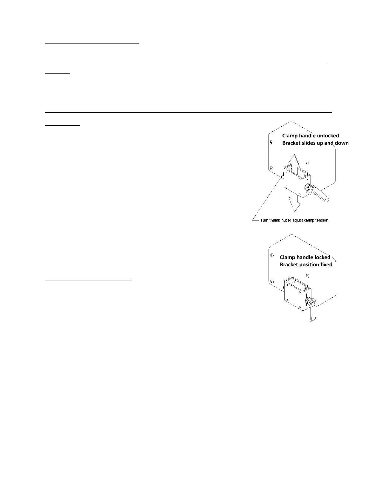
Belt Tension
Unlock the clamp lever and slide the motor unit down on its mounting
bracket slots with your hands to tension the belt. Pull the belt snug by
putting downward pressure on the motor box with your hand and then
locking the clamp lever. The clamp lever tightness can be adjusted by
unlocking the lever and tightening or loosening the knurled thumb nut.
Do not over-tension the belt. Excessive tension causes clutch wear,
makes the clutch difficult to operate and may damage the motor shaft.
Over-tensioning also removes any beneficial “give” in the drive system.
If it doesn't slip it is tight enough. An over-tightened belt will not
allow any give; a less tensioned belt will give warning of heavy loads or
striking the rudder-stops with a skip and thump. The hose-clamps on
the pedestal bracket may need to be tightened after the foam scratch
pads compress. Pedestal installations using a reverse mounting plate
may sometimes need the bracket directly fastened to the pedestal with
screws if the hose-clamps slip under heavier loads.
Pulley and Clutch Maintenance
The drive pulley is held in one of two positions (engaged or disengaged)
on its shaft by a detent (spring-loaded ball), which fits into one of two
grooves on the shaft. All parts are made of Delrin, ylon or stainless
steel.
Most clutch wear is caused when hand-steering under high belt tension
without lubrication. Lubricate the drive pulley and shaft periodically. Salt water may leave salt crystal build-up
in the detent. The Delrin drive pulley should be removed from the drive-plate, cleaned and oiled or greased
periodically—more often in severe or heavy use conditions.
If the autopilot will not be steering for awhile, remove the belt from the small pulley and hang it over the
binnacle or wheel shaft. This will lessen wear and prolong the life of the clutch when hand steering.
Ea h season servi e and lubri ate the lut h/drive pulley. You should not remove the drive-plate unless the
broken head of a shear-pin is stu k behind the drive-plate.
·
Loosen tension on the drive belt and remove belt from the small pulley.
·
Remove the two screws from the back of pulley cap; these are the shear-pins. (The black, grooved grip
used to engage and disengage the clutch is the pulley cap. The screws are the machined shear pins.) Do not
attempt to remove the shear-pins if the pin ends are bent. Rea h and straighten them with long-nosed
pliers or a small vise grip first.
·
Remove pulley cap.
·
Remove stainless steel retaining clip from its groove at the end of the shaft.
PAGE 16 OF 21
·
Remove pulley gear.
·
Rinse pulley in fresh water. Work the ball inside the shaft-hole in and out.
·
Clean, dry and lubricate shaft. Work lubrication into the ball inside the shaft-hole.
·
Replace pulley, retaining clip, and pulley cap.
·
Replace the two shear screws. Do not over-tighten screws, they can strip or the pulley may distort. Rotate
the pulley on the shaft and observe the ends of the shear screw pins.
Shear Pin Clearance Adjustment and Clutch Maintenance
There should be an even gap (1/16" approx.) between the end of the shear pins and stainless steel shaft-plate. If
one of the pins is too close to shaft-plate, it may tend to catch in the plate holes when the wheel is turned. If the
pulley does not turn freely, the pins are not even, or the pins are too close to the shaft-plate, back off one or
both of the screws slightly. There is a slotted set-screw in the gear teeth to adjust the spring and ball détente.
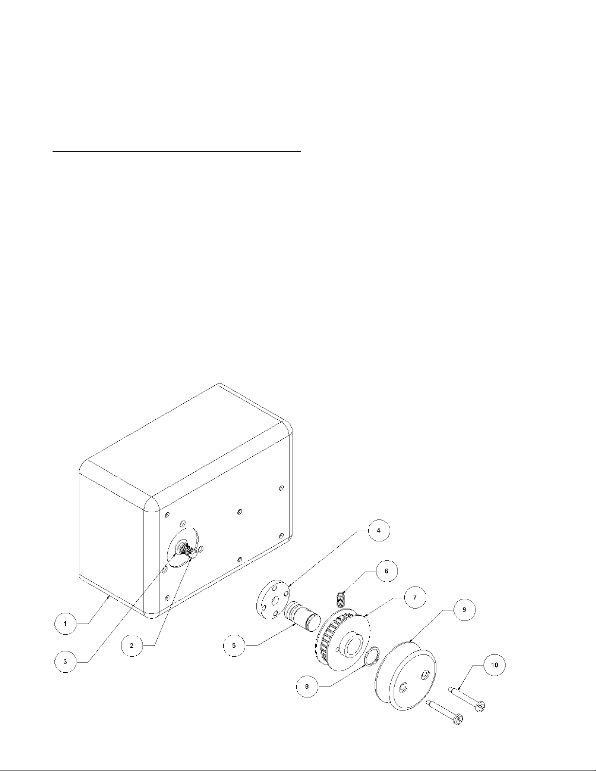
The drive-plate
(4)
does not need to be removed as part of normal maintenance. It may need to be removed if a
broken shear screw
(7)
head becomes trapped behind it. There is a hole in the shaft. To remove the drive plate,
insert a narrow screw-driver and unscrew the stainless shaft from the motor shaft (it has normal threads—
rotate shaft counter-clockwise to loosen). Gently pry the circular plate off the knurled motor shaft; gently pry
all around the plate, force is not needed. Do not remove or lose the black-rubber watertight seal (O-ring)
found under the plate. Clean the drive plate, shaft, and hub of the clutch gear. Oil or grease the parts before re-
assembly. Be sure to work some oil into the detent ball that protrudes into the hub of the clutch gear. Replace
belt and adjust the belt tension.
Item # Part # Part Name
1 Motor Box
2 Motor Shaft
3 37-0004
Motor Shaft O-Ring,
si e 110
4 53-0009 Drive Plate
5 53-0012 Drive Shaft
6 98-0039 Ball Spring Detent
7 53-0007 Drive Pulley Gear
8 42-0013 Retaining Ring 5/8"
9 98-0027 Pulley Cap
10 98-0030 Shear Screw #10-32

CPT Autopilot Operation Manual
© 2018 CPT AUTOPILOT INC. VERSION 22 PAGE 17 OF 21
Connector Maintenance
Connectors for the power cable and control cable, if installed, should be maintained by applying silicone
dielectric grease to both plug and socket contacts each season. Caps should be in place and tight if plugs are
not fitted together. Connectors are a liability if not maintained and kept greased. The cable jacket should be
kept sealed and not open or exposed. Corrosion inhibitor, Boeshield T-9 or similar lubricants should OT be
used on electrical contacts as they can leave an insulating film which inhibits electrical connections and is
difficult to remove.
The CPT cables are not detachable from their boxes. The black cable fittings on control box and motor box are
not plugs—do not loosen them. Attempting to remove them will void the warranty and may cause damage. The
control box cable and power cable are soldered directly to circuit boards inside the boxes. An extension cable is
available to easily extend the length of the control cable without cutting the cable. After sea trials the control box
cable may be cut and spliced for routing or connected to a terminal block below deck. The cable is color coded and
shielded. Be sure the power wires are completely disconnected from the battery before cutting the control
cable.
Wheel Pulley
After a season or two, check to make sure the wheel pulley is still centered on the steering wheel and adjust if
needed. Do not over-tighten J-bolts or the pulley will warp and distort over time. Tighten J-bolt until it
makes onta t and grips the spoke, then tighten the nut only another ¼ turn. (See Installation Manual)
Factory Service
It is recommended that the CPT be returned to the factory to have the watertight seals replaced every 10 years
depending on weather exposure and amount of use. This is also worthwhile if it has been used for many years
and you are planning an extensive passage. There is a nominal charge, but if the seals become worn or brittle
and salt water enters the unit, repairs may be extensive. The motor box and control box should be securely
bubble-wrapped with ½" bubble-wrap, then separated by cardboard and boxed, and boxed again with 1" of
peanuts when shipping.
Troubleshooting
Specialized equipment is required to service the CPT; there is no internal fuse or other internal parts that are
owner-serviceable. For satisfactory and warranted repairs, repairs should be done only by the factory.
U AUTHORIZED REPAIR ATTEMPTS VOID THE WARRA TY REGARDLESS OF CIRCUMSTA CE
Does ot Steer In Either Direction
Be sure shear pins are not damaged and that clutch is engaged.
Test that CPT has a good 12-volt power connection, with no oxidized connections. Check battery voltage (12
volts minimum), check voltage at power cable connection as pilot motor runs or would normally attempt to
run (turn rudder to 10 and set to tack). A large voltage drop when the motor attempts to run indicates poor
12-volt connections and/or inadequate wire size. Trace power circuit back to the power supply for breakage,
loose/oxidized connections, a blown fuse, defective fuse holder, etc. Poor connections, switches, and small
gauge wires can cause voltage drop, blown fuses and damaged circuits. The pilot will compensate for voltage
drop by drawing more current.
With the belt off and clutch engaged, turn the rudder control to 10 and tack to port or starboard; if you grip
the small drive pulley with your hand you should feel good torque and not be able to stop the motor.
Motor: Engage the clutch after 1 minute warm-up, set rudder 5, deadband 1, toggle to hold-heading and press
10-degree button: CPT motor should rotate to make a heading correction. If there is no response, try back-
driving the motor briefly by turning boat’s wheel by hand; if this brings a response from the motor, it may be

PAGE 18 OF 21
an indication of worn brushes or carbon build-up in the motor after seasonal storage. Back-driving the motor
by hand may clear carbon build-up and restore brush contact.
Motor turns the wheel the Wrong Direction
The direction the motor rotates must be set for the wheel to turn the correct direction; it has been preset for
your installation at the factory. See Changing the Changing the Motor Rotation on page 7.
Motor Runs But Drive Pulley Does ot Rotate
Check that shear screws are not broken or bent. The stainless drive-plate is fastened to the motor shaft by a
setscrew. If the stainless drive-plate is loose, use a 1/8" hex key to remove Locking Set Screw. Tighten Cone
Point Set Screw. Replace and tighten locking set screw. See diagram on page 16.
Motor will also turn very slow/weak if there is too much voltage drop in power wires.
Unit Will Steer/Turn in Only One Direction
Try turning the pilot off and restarting with the required 60 second warm-up.
Be sure there is no magnetic interference, and that the magnetic reference was set for your hemisphere; it is
pre-set for the northern hemisphere at the factory, but can be changed as needed.
During the warm-up period the sensor heading will drift. Allow at least 1 minute for the pilot to warm-up
after powering it on. Keep the vessel on a consistent heading for 30 seconds before flipping to Hold Heading. If
the pilot is toggled to Hold Heading without adequate warm-up time, it may turn and pulse frequently (once
per second) in the same direction. At the dock, while the boat is stationary and unable to respond, it is normal
for the pilot to make a small correction every 10 seconds.
Continual turning one direction once per second while sailing or if the pilot steers on some headings but not
others may be an indication of magnetic interference near the control box or failure to set the magnetic
reference for your hemisphere. Refer to the section “Setting the Magnetic Reference” on page 7.
Under Steers, Boat Does ot Reach Heading Or Does So Slowly, Eventually Falling Off-Heading
Small repeated heading corrections in one directions indicates the Rudder control is too low - increase setting;
turn rudder high as possible without causing over-steering. It may also indicate the Deadband is set too high—
lower deadband setting (may be both conditions). Make sure boat is making adequate headway, set Deadband
to lowest setting, Rudder high enough so that one motor-pulse brings the boat back to the rumbline.
Some spade rudders on racing-type hulls are easily understeered or oversteered, and the best rudder setting
may be a compromise between the two.
Over steers, Passes Course, “S” Turns
Rudder control set too high – use lower setting. Deadband may be too low – increase the setting (may be
both).
Rhythmic Steering, Corrects as Boat Rolls with Swells
Deadband set too low – increase setting.
Frequent Corrections to Port/Starboard, Rudder and Deadband Controls Ineffective: Wheel Play
This is typically from too much play in the steering system, or air bubbles, foaming or valve delay in hydraulic
systems. The boat’s rudder will not center, and play will alternate between port and starboard sides. The pilot
tends to only hold heading within 10-20 degrees or more, understeering on one side, oversteering on the other,
and the best rudder dial setting will be a compromise between the oversteering and understeering. Adjusting
the rudder and deadband dials may seem to have little effect. To check for play in the steering system:
While having someone holding and locking the rudder quadrant to one side, measure how far the wheel turns.
Place 18” of masking tape on the outside perimeter of the wheel, centered at the top of the wheel, top-dead-
center (TDC).

CPT Autopilot Operation Manual
© 2018 CPT AUTOPILOT INC. VERSION 22 PAGE 19 OF 21
Slowly rotate wheel starboard until it will not turn further: mark the tape TDC.
Slowly rotate wheel port until it will not turn further: make a mark on the tape TDC.
Measure the distance between the two lines: ___" Circumference of Wheel :____"
Divide the circumference of your wheel by 360; the answer is the distance for one degree of wheel play for your
wheel. Poor performance may occur if wheel play is more than 25 degrees. Wheel play in hydraulic systems
can be harder to measure and may only occur under heavier loads or intermittently depending on the cause.
Belt Slips, belt adjustment, Excess Torque
The belt should be snug, but over-tensioning is not needed and will make the clutch hard to operate. Increase
the belt tension if the belt jumps in the cogs under load: unlock the clamp lever, push down on the motor box
and relock the clamp lever. The boat must be balanced to lessen weather-helm and provide consistent steering
(See “Sail Trim”). Check the steering system for binding, bad control cable leads, damage, or lack of
lubrication. Correct as necessary. Make sure wheel pulley is centered on wheel, and that belt is aligned. Make
sure hose-clamps and bracket are tight and have not slipped on pedestal. For pedestal diameters less than 4”,
heavy wheel loads, or reversed pedestal installations: the pedestal bracket should be directly fastened to the
pedestal with screws in addition to hose-clamps. If heavy loads cause the motor to flex the mounting so the
belt slips, a belt tensioner will keep the belt tensioned and absorb shock loads from large rudders.
Clutch Disengages
Motor unit may be tilted so the drive pulley shaft is not parallel to the wheel shaft, and belt tension is
disengaging the clutch. Pulleys must be aligned and parallel when the clutch is engaged. If in doubt or the
wheel is not uniform favor a slight belt slant that will help keep the clutch engaged.
The set-screw recessed into the drive pulley-gear adjusts the friction of the ball bearing detente in the clutch.
Slightly tightening this screw will lock the clutch more securely in position; tightening too much will make the
clutch difficult to disengage. This normally does not need adjustment unless it has worked loose or there has
been extensive wear. Use a small bit of thread locker if the screw has worked loose.
Shear Pin Breakage
Be sure all excess friction is removed from the steering system. Steering linkage with excessive play can
transfer sudden shock loads from the rudder directly to the shear pins. Be sure the wheel pulley is basically
centered on the steering wheel. Vessels with excessive rudder shock loads will benefit from use of a belt
tensioner which acts as a shock-absorber.
If the tip of a broken shear pin is not removed, it may get lodged behind the drive-plate and cause a screeching
sound behind the clutch. Remove the clutch & drive-plate to remove the broken tip.
A worn clutch pulley with excessive hub wear will no longer rotate on center and be wobbly, transferring belt
tension to the shear pins instead of the hub and shortening shear pin life; contact us for a replacement pulley
gear. To prolong the life of the clutch and shear pins when hand steering, loosen tension or remove the belt
from the small pulley, and hang the belt on over the binnacle or wheel shaft. Clean and lubricate clutch on a
regular basis.
CPT Steers +/- 10 degrees or more in seas, worse in flat water
Be sure the Deadband is set to the lowest setting. Otherwise this is usually an indication of excess play in the
boat's steering system or some magnetic interference. Excess play at the wheel must be removed. Inspect and
tighten cable systems. Air, foaming and valve delay in hydraulic steering systems must be removed. Try
relocating the control box away from stereo speakers and any metallic equipment that may have a magnetic
field; only 316 stainless fasteners should be used to mount the control box.
Table of contents
Other CPT AUTOPILOT Marine Equipment manuals

Popular Marine Equipment manuals by other brands

Teledyne
Teledyne SeaBat T Series Quick reference guide

Simrad
Simrad ED162 Operator's manual

Veratron
Veratron VMH 70 user manual

MasterCraft
MasterCraft HV700 owner's manual

MOFLASH SIGNALLING
MOFLASH SIGNALLING SD125 Series INSTALLATION & TECHNICAL INFORMATION

Sealite
Sealite TRIDENT-3000 Installation & service manual

Oceanic
Oceanic Pressure Gauge owner's guide

JRC
JRC JQE-103 - brochure

Pittway
Pittway SYSTEM SENSOR SpectrAlert CH12/24 Installation and maintenance instructions

Scanstrut
Scanstrut Scanpod Deck Pod installation instructions

E2S
E2S A100SONTEL Instructions/service manual

KVH Industries
KVH Industries FB250 installation guide


