CPT AUTOPILOT CPT User manual

INSTALLATION MANUAL
MANUFACTURED AND SOLD DIRECT BY
CPT AUTOPILOT INC.
7960 B Soquel Drive #114 Aptos CA 95003 USA
www.cptautopilot.com email: [email protected]


INSTALLING THE CPT AUTOPILOT
The CPT Autopilot has been installed in a large variety of sailing and motor vessels, in many different configurations.
Mounting the CPT on a pedestal or bulkhead is normally a quick and easy installation. This manual also has advice for
alternative installations, including slanted gear-driven heels, ooden heels, and large oversized heels. This manual
ill help you choose the best installation method for your boat.
The CPT is an extra cre member to man the heel, day or night, rain or shine. It is amazing to take your hands off the
heel and experience the freedom the CPT provides!
WARNING!
▷ Always remember to maintain a proper look-out.
▷ Do not use the CPT in tra ic or in waters where navigation is restricted.
▷ An autopilot is NOT a substitute or good seamanship.
▷ Always maintain a permanent watch by the helm.
▷ Keep children and pets away rom the autopilot belt.
INTERNATIONAL REGULATIONS FOR PREVENTING COLLISIONS AT SEA, 1972 (72
COLREGS)
Part B - Steering and Sailing Rules
Section 1 - Conduct of Vessels in any Condition of Visibility
Rule 5 - Lookout
Every vessel shall at all times maintain a proper look-out by sight and hearing as ell as by all available
means appropriate in the prevailing circumstances and conditions so as to make a full appraisal of the
situation and risk of collision.
MANUFACTURED AND SOLD DIRECT BY
CPT AUTOPILOT INC.
7960 B Soquel Drive, #114, Aptos, CA 95003 USA
Website: .cptautopilot.com
Email: [email protected]
Version: 22, Updated: April 2019
Applies to autopilots manufactured after June 2017
(Serial number 100746 and higher)

PAGE 2 OF 26
HOW TO USE THIS MANUAL
1. Revie “Mounting the Motor Box” page 7 to decide ho the CPT can best be mounted in
your cockpit. The standard pedestal, bulkhead, or L-bracket mounts are the easiest, most
straightfor ard installations.
2. Do nload installation templates from our ebsite. Print the templates and use them to get
the measurements for mounting the autopilot. Send us your measurements and order your
autopilot through our ebsite ( .cptautopilot.com), over email (info@cptautopilot.com),
or by calling us at 831-687-0541.
3. When your autopilot arrives, follo the instructions for installing the CPT. Then perform the
“Dockside Check-Out” and “Sea Trials” in the Operation Manual.
4. To become more familiar ith the CPT, revie the CPT Operation Manual.
If you have any questions or suggestions for improving this manual, please let us kno . We are al ays
pleased to receive photos of CPT installations and suggestions for improving the CPT.

CPT Autopilot Installation Manual
© 2018 CPT AUTOPILOT INC. VERSION 21 PAGE 3 OF 26
Ho to Use this Manual ............................................................................................................... 2
Parts List.......................................................................................................................................... 4
Standard Parts................................................................................................................. 4
Additional Parts (optional)........................................................................................... 4
Installation Summary .................................................................................................................... 4
Mounting the Wheel Pulley.......................................................................................................... 5
Wheels ith Metal Spokes ............................................................................................ 5
Wheels ith Wooden Spokes ....................................................................................... 6
Wheel Pulley Hole Diagram ......................................................................................... 6
Mounting the Motor Box.............................................................................................................. 7
Standard Pedestal Mount...................................................................................................... 8
Pedestal Kit Parts Diagram ........................................................................................... 9
Standard Pedestal Mount ith Dropdo n Plate............................................................. 10
Dropdo n Plate Parts Diagram ................................................................................. 11
Reverse-Vertical Pedestal Mount....................................................................................... 12
Reverse-Vertical Pedestal Mount Diagrams, Starboard Side................................. 13
Reverse-Vertical Pedestal Mount Diagrams, Port Side........................................... 14
L-Bracket Mount.................................................................................................................. 15
L-Bracket Parts Diagram............................................................................................. 16
Bulkhead or Square Pedestal Mount ................................................................................. 17
Tilted or Angled Wheels ..................................................................................................... 19
Oversize and Large Wheels................................................................................................. 19
Mounting Problems Not Addressed.................................................................................. 19
Electrical Connection .................................................................................................................. 20
Splicing Control Box Cable ........................................................................................................ 20
Changing the Motor Rotation.................................................................................................... 20
Setting the Magnetic Reference.................................................................................................. 21
Control Box Orientation Restrictions....................................................................................... 21
Mounting the Control Box ......................................................................................................... 22
Control Box Mounting Requirements ...................................................................... 22
Testing the Control Box before final mounting....................................................... 23
Troubleshooting........................................................................................................................... 24
Ho to Check for Magnetic Interference................................................................................. 24

PAGE 4 OF 26
PARTS LIST
Before beginning the installation, unpack and identify all parts. Refer to the packing list for the complete list of parts for
your order.
Standard Parts
· Motor Box (larger box ith clutch/gear on back) /10' po er cable
· Control Box /heading controls, attached to motor box /10' cable
· Wheel Pulley, 12.75ʺ diameter (for clamping to steering heel)
· Drive belt
· J-Bolts ith nuts and ashers (quantity and size to suit boat's heel)
· Control Box Bracket (peel off hite or grey plastic protective covering)
o Short Control Box Bracket for pedestal rail and bulkhead mounting
o Long Control Box Bracket for console and overhead mounting
o Pipe Clamp for mounting to pedestal/guard rail pipe
· Motor Box Bracket for mounting motor box to bulkhead or pedestal kit (slotted aluminum bracket)
· Clamping lever ith ashers and knurled thumb nut for mounting motor box
· Spare shear pin set
· In-line fuse
· Installation Manual and Operation Manual
Additional Parts (optional)
· Pedestal Mount Kit (deep or shallo ) ith hard are, hose clamps and anti-scratch foam pads
o Peel off hite plastic protective covering
· L-Bracket, Drop-do n Plate, or Reverse-mount Plate for mounting motor box
· Shims for mounting motor box
· Spoke spacers for heel pulley
· Waterproof plug and receptacle for 12-volt po er supply
INSTALLATION SUMMARY
1. Mount the large heel pulley and belt onto the steering heel (page 5)
2. Mount the motor box to the pedestal, bulkhead, console or deck (page 7)
3. Mount the control box. (page 22)
4. Run the po er cable to the 12-volt po er source (page 2020)
5. Test the autopilot: Dockside checkout and Sea Trials (Operation Manual)
This installation can normally be completed in an afternoon, depending on the particular boat, installer, and ease of
heel removal.
The power cable and control box cable are not removable. The black cable glands are not removable plugs and
should not be loosened or disturbed due to the watertight seals. Do not attempt to open the control box or
motor box, there are no user serviceable parts inside. Loosening the black cable glands or opening the unit
will void your warranty.
Do not cut, splice or route the control box cable before sea trials. Do not cut any wires or it owner plugs until
a ter success ul sea trials, hen you are sure of the mounting location for the control box! The po er cable
must be completely disconnected from battery or po er source before the cable is cut to avoid circuit damage.
The cable can be cut at a point here the splice ill be inside and dry. The standard cable length is 10 ft ith an
inline 1/2ʺ diameter bayonet-style connector located 18ʺ from the motor box. An extension cable is available to
easily extend the length of the control cable ithout cutting the cable. The control cable is an unshielded jacketed
cable ith six 24ga color-coded ires. Solder and heat-shrink the splices, or use a terminal block ith soldered
lugs, keeping the splice or terminal block shielded. A aterproof connector may be used on the po er cable. (See
“Electrical Connection”)
CPT Autopilot Installation Manual
© 2018 CPT AUTOPILOT INC. VERSION 21 PAGE 5 OF 26
MOUNTING THE WHEEL PULLEY
Wheels ith Metal Spokes
1. Remove the heel and place it horizontally. (On older boats, this
may require a gear puller. Grease shaft before replacing the heel
and you ill have less trouble next time.)
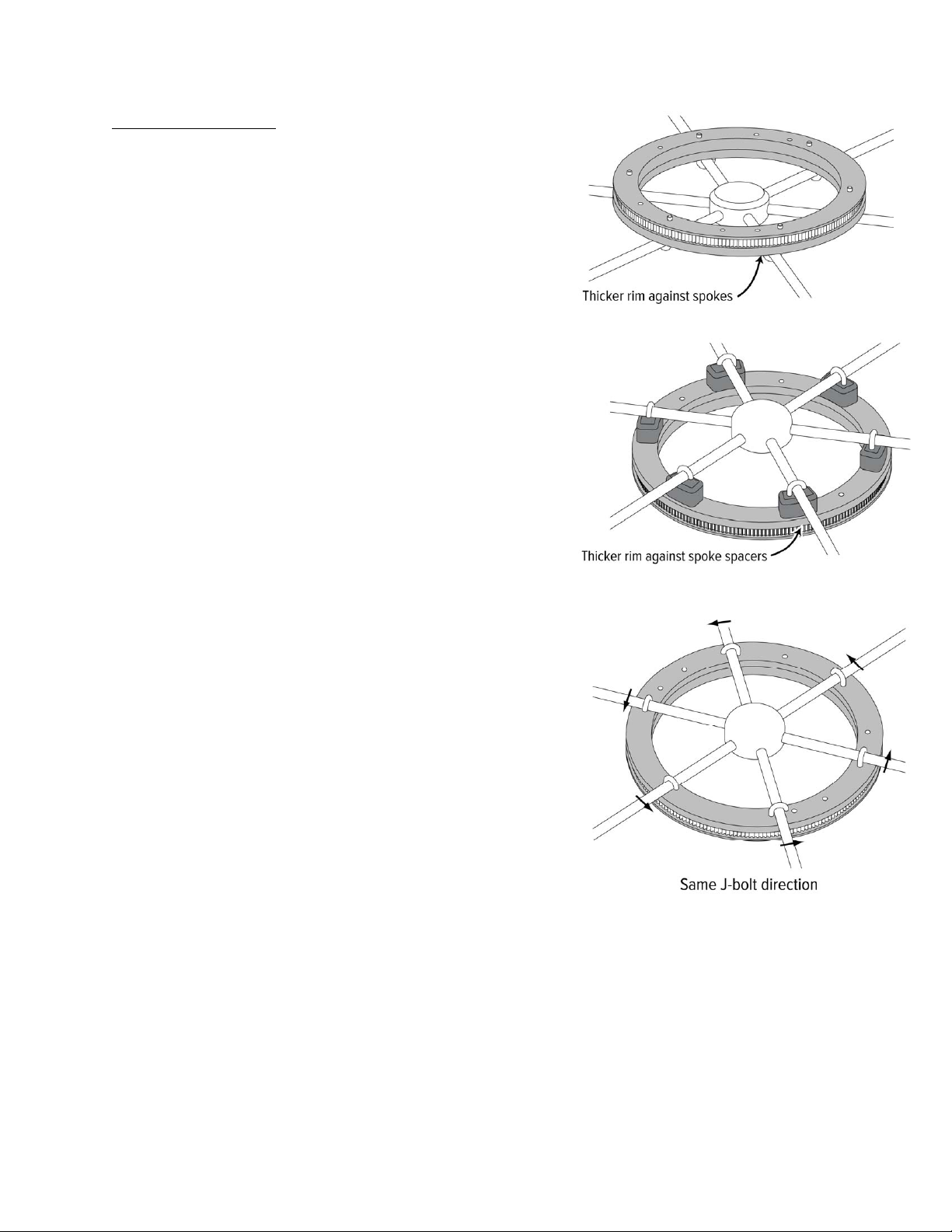
2. Place the Wheel Pulley on backside of heel ith the thicker rim
against the spokes. Hook the J-Bolts on the spokes, and pass them
through the pulley holes. Refer to the hole diagram to find the holes
for your spoke pattern. Put a drop of oil, flat asher and a nut on
each J-bolt. Tighten nuts just enough to hold the pulley temporarily
in place. Position pulley roughly in the center of the heel.
· Orient the J-bolts so they hook over the spokes from the same
side. If the bolts are not hooked over in the same direction the
pulley ill not center on the heel.
· If spoke spacers are needed, install them bet een the spokes
and the thicker rim of the pulley.
3. Inspect fit of the pulley against the spokes. If spokes are out of
alignment or not in plane and sho a gap or space ith the pulley,
the lo spokes may need to be shimmed. DO NOT attempt to pull
them into alignment by tightening the J-bolts—the pulley ill arp.
On dished heels or tapered spokes: if the gap on the outside edge is
large, use tapered shims bet een pulley and spokes to even the
backing on the pulley.
4. Temporarily remount steering heel ( ith mounted pulley).
Overlong J-bolt stems can be cut off flush later or covered ith
black vinyl caps (included).
5. The heel pulley ill tend to self-center, but check centering:
· As an indicator, mount a tool (a taped coffee stick, or coat-
hanger taped to the pedestal, for example) ith its tip close to
pulley. Tape it solidly to pedestal so it does not move (refer to
diagram on follo ing page).
· Rotate the heel.
· Use your hand to tap the pulley to adjust its center position
until distance bet een pulley and pointer is fairly uniform, ±⅛"
is fine.
6. Tighten J-bolt nuts.
· Do not over-tighten J-bolts, use a nut driver or small rench: tighten the nut until the back of the J-bolt
grips the spoke and begins to resist s inging, then turn the nut only another ¼ turn.
· The pulley may eventually arp or distort if the J-bolts are over-tightened.
7. Place the belt on the pulley and replace the heel.

PAGE 6 OF 26
Wheels ith Wooden Spokes
Proceed in the same general fashion as for metal-spoked heels. If
preferred the spokes can be padded to prevent crushing the ood or
damaging the varnish under J-bolts. Clear vinyl tubing cut to length
and slipped over J-bolt hooks orks ell.
If you prefer not to use J-bolts, you may scre the pulley directly to the
heel using self-tapping or ood scre s (Use pan-head scre s ith
ashers, not flat-head scre s):
1. Temporarily fasten pulley to heel ith tape or a lashing of light
line.
2. Center pulley as described in step 5.
3. Mark and drill pilot holes in ooden spokes for fasteners.
4. If desired, use bedding compound in the holes to fill any gap ith
the fasteners used.
Wheel Pulley Hole Diagram
Indicator used
to center the
wheel ulley
CPT Autopilot Installation Manual
© 2018 CPT AUTOPILOT INC. VERSION 21 PAGE 7 OF 26
MOUNTING THE MOTOR BOX
(Only after the heel pulley is mounted)
· STANDARD PEDESTAL MOUNT (page 8): The Pedestal Bracket is designed to mount on most round (cylindrical)
pedestals. It comes in t o sizes (shallo bracket for spoke-to-pedestal clearances from 2-3/4ʺ to 3-3/4ʺ, and deep
bracket for spoke-to-pedestal clearances over 3-3/4ʺ).
· STANDARD PEDESTAL MOUNT WITH DROPDOWN PLATE (page 10): The dropdo n plate lo ers the motor
box belo the pedestal bracket so that bracket doesn’t hit the base of the pedestal.
· REVERSE-VERTICAL PEDESTAL MOUNT (page 12): If there is limited room belo or aft of the heel, a vertical
motor box is available that can be reverse-mounted for ard of the heel. The drive pulley faces for ard instead of
aft; the motor rotation is reversed. The motor box may also be mounted ith the drive pulley inside the perimeter of
the heel if 1ʺ spacers are used bet een the spokes and the heel pulley. Due to increased leverage on the pedestal
bracket, it may require scre s for mounting instead of hose-clamps.
· L-BRACKET MOUNT (page 15): Mounting on a surface that is parallel to heel shaft, such as a coaming, side all,
deck or cabin sole requires the L-bracket.
· BULKHEAD MOUNT (page 17): The motor box bracket by itself can be used ith appropriate shims to mount the
motor box assembly directly onto a console or bulkhead parallel to the boat's heel. Teak or marine-board shims are
used to align the drive belt ith the heel.
· TILTED WHEELS (page 19): The L-bracket is used to mount motor box on cockpit sole or cockpit side- all for boats
ith tilted heels or slanted gear-driven heels.
· OVERSIZED WHEELS (page 19): The L-bracket is used to mount motor box to deck or side all in boats ith large
heels, or “deck-s eeper” heels.
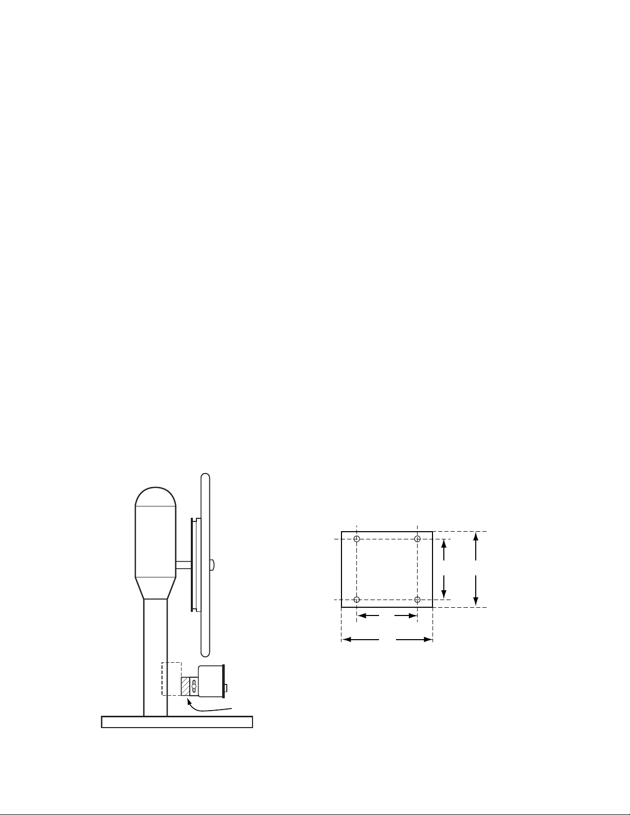
Shim
Shims can be used to obtain proper belt alignment bet een drive pulley and heel pulley.
3"
2"
2"
2 ½"
Use #10 scre s
(#7 or 3/16ʺ drill size)
Shim Dimensions
PAGE 8 OF 26
Standard Pedestal Mount
Install Motor Box onto Pedestal Bracket
1. Fasten the slotted motor box mounting bracket to the bottom of pedestal bracket using the four #10 scre s and any
needed shims.
If a shim is needed for aligning the belt ith the heel, the thickness is based on the clearance distance bet een your
spokes and pedestal (measured 5ʺ / 127mm out from the center of your heel).
2. Mount the motor box onto the slotted bracket using the clamp lever, ashers and knurled thumbnut. Lock the
clamping lever hen the slotted bracket is in the middle of its adjustment range—centered in the slots.
3. Hang assembly from belt and hose-clamp to pedestal.
Place the drive pulley of the motor box in the belt, and allo the box and bracket assembly to hang in the belt and
rest snug against the pedestal hile you support it.
Align belt ith heel and tighten hose-clamps
1. Attach the adhesive foam pads to the hose-clamps, not the pedestal. Pass the hose-clamps through the slots from the
inside of the bracket around the pedestal and loosely tighten.
2. Adjust the clearance from the pedestal:
· For the Deep Pedestal Bracket, the belt should align ith the heel hen the edge of the stainless bracket is
2 ½ ʺ (64mm) from most pedestals using any required shims; see clearance chart belo .
· For the Shallow Pedestal Bracket, the belt should align ith the heel hen the edge of the stainless
bracket is 1ʺ (25mm) from most pedestals using any required shims; see clearance chart belo .
3. Temporarily tighten the hose-clamps enough to hold the assembly in position.
4. Check for alignment: hold a yardstick or straight-edge against the back of the heel adapter; it should be fairly
parallel ith the belt hen vie ed from the side (clutch engaged; pushed in). Also look from above the heel and
from the side to be sure the motor box is square ith the heel from all directions and not at an angle. If the belt is
not parallel you can squeeze the stainless bracket deeper or shallo er onto the pedestal as needed, or add or remove a
shim. If in doubt or your heel is not uniform, favor the motor box being closer to the pedestal (rather than farther).
The slight belt slant ill pull the clutch in hich ill help keep the clutch engaged.
Shallo Pedestal Bracket
Deep Pedestal Bracket
Spoke-to-pedestal clearance Shim Thickness Bracket edge to pedestal
3.75ʺ (95mm) 0 (no shim) 2.25ʺ (5.7mm)
4ʺ (102mm) 0 (no shim) 2.5ʺ (6.4mm)
4.125ʺ (105mm) 0.125ʺ shim (3mm) 2.5ʺ (6.4mm)
4.25ʺ (108mm) 0.25ʺ shim (6mm) 2.5ʺ (6.4mm)
4.375ʺ (111mm) 0.375ʺ shim (10mm) 2.5ʺ (6.4mm)
4.5ʺ (114mm) 0.5ʺ shim (13mm) 2.5ʺ (6.4mm)
4.625ʺ (117mm) 0.625ʺ shim (16mm) 2.5ʺ (6.4mm)
4.75ʺ (121mm) 0.75ʺ shim (19mm) 2.5ʺ (6.4mm)
4.875ʺ (124mm) 0.875ʺ shim (22mm) 2.5ʺ (6.4mm)
5ʺ (127mm) 1ʺ shim (25mm) 2.5ʺ (6.4mm)
Spoke-to-pedestal clearance Shim Thickness Bracket edge to pedestal
2.25ʺ (57mm) 0 (no shim) 0.75ʺ (1.9mm)
2.5ʺ (64mm) 0 (no shim) 1ʺ (2.5mm)
2.625ʺ (67mm) 0.125ʺ shim (3mm) 1ʺ (2.5mm)
2.75ʺ (70mm) 0.25ʺ shim (6mm) 1ʺ (2.5mm)
2.875ʺ (73mm) 0.375ʺ shim (10mm) 1ʺ (2.5mm)
3ʺ (76mm) 0.5ʺ shim (13mm) 1ʺ (2.5mm)
3.125ʺ (79mm) 0.625ʺ shim (16mm) 1ʺ (2.5mm)
3.25ʺ (83mm) 0.75ʺ shim (19mm) 1ʺ (2.5mm)
3.375ʺ (86mm) 0.875ʺ shim (22mm) 1ʺ (2.5mm)
3.5ʺ (89mm) 1ʺ shim (25mm) 1ʺ (2.5mm)
Top Vie

CPT Autopilot Installation Manual
© 2018 CPT AUTOPILOT INC. VERSION 21 PAGE 9 OF 26
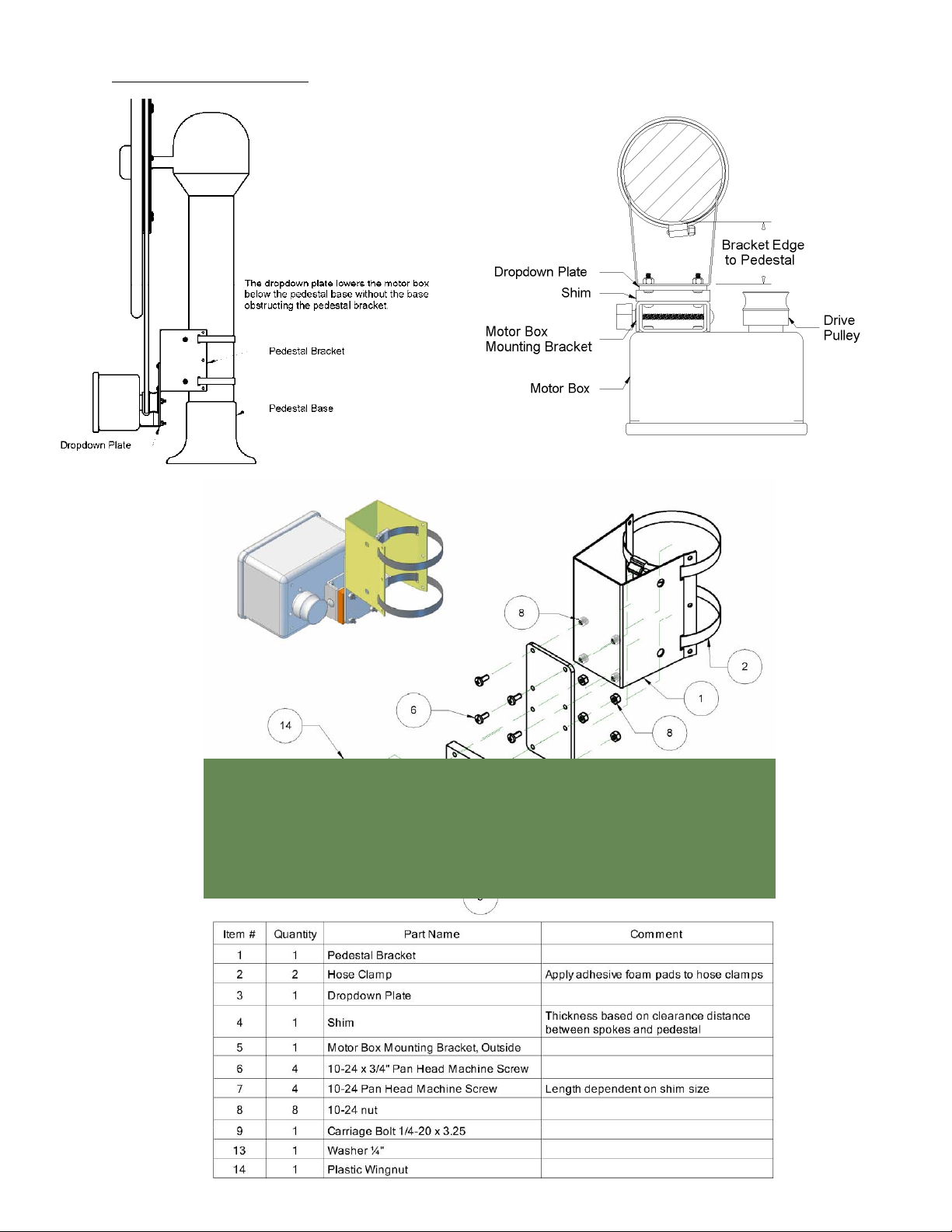
Pedestal Kit Parts Diagram

PAGE 10 OF 26
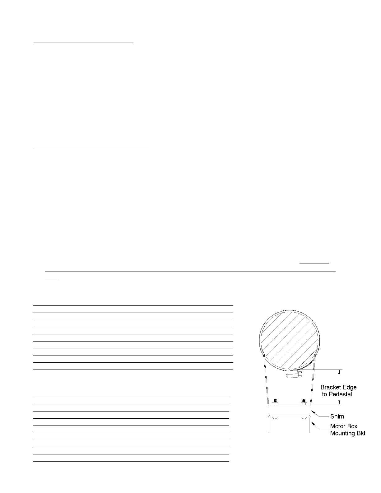
Standard Pedestal Mount ith Dropdo n Plate
The dropdo n plate lo ers the motor box belo the pedestal base
ithout the base obstructing the pedestal bracket.
Install Motor Box onto Pedestal Bracket and Dropdo n Plate
1. Fasten the slotted motor box mounting bracket to the bottom of
the Dropdo n Plate using any needed shims and the four
#10 scre s.
If a shim is needed for aligning the belt ith the heel, the
thickness is based on the clearance distance bet een your spokes
and pedestal (measured 5ʺ out from the center of your heel).
2. Fasten the Dropdo n Plate to the Pedestal Bracket using four
#10 scre s.
3. Fasten the motor box to the slotted mounting bracket using the
clamp lever, ashers and knurled thumbnut. Lock the clamping
lever hen the slotted bracket is in the middle of its adjustment
range—centered in the slots.
Hang assembly from belt and hose-clamp to pedestal
Place the drive pulley of the motor box in the belt allo ing the box and bracket assembly to hang in the belt and rest snug
against the pedestal hile you support it. Do not tighten the hose clamps yet.
Align belt ith heel and tighten hose-clamps
1. Attach the adhesive foam pads to the hose-clamps, not the pedestal. Pass the hose-clamps through the slots from the
inside of the bracket (start from the side ith the t o holes), around the pedestal and loosely tighten.
2. Adjust the clearance from the pedestal:
· If using the Deep Pedestal Bracket, the belt should align ith the heel hen the edge of the stainless bracket is
2 ½ ʺ (6.4mm) from most pedestals using any required shims; see clearance chart belo .
· If using the Shallow Pedestal Bracket, the belt should align ith the heel hen the edge of the stainless
bracket is 1ʺ (2.5mm) from most pedestals using any required shims; see clearance chart belo .
3. Temporarily tighten the hose-clamps enough to hold the assembly in position.
4. Check for alignment: hold a yardstick or straight-edge against the back of the heel adapter; it should be fairly
parallel ith the belt hen vie ed from the side (clutch engaged; pushed in). Also look from above the heel and
from the side to be sure the motor box is square ith the heel from all directions and not at an angle. If the belt is
not parallel you can squeeze the stainless bracket deeper or shallo er on the pedestal as needed, or add or remove a
shim. If in doubt or your heel is not uniform, favor the motor box being closer to the pedestal (rather than farther).
The slight belt slant ill pull the clutch in hich ill help keep the clutch engaged.
Shallo Pedestal Bracket Clearance Chart
Deep Pedestal Bracket Clearance Chart
Spoke-to-pedestal
Clearance Shim Thickness
Bracket edge
to pedestal
3.75ʺ (95mm) 0 (no shim) 2.25ʺ (57mm)
3.875ʺ (98mm) 0 (no shim) 2.375ʺ (60mm)
4ʺ (10.2mm) 0 (no shim) 2.5ʺ (64mm)
4.125ʺ (105mm) 0.125ʺ shim (3mm) 2.5ʺ (64mm)
4.25ʺ (108mm) 0.25ʺ shim (6mm) 2.5ʺ (64mm)
4.375ʺ (111mm) 0.375ʺ shim (10mm) 2.5ʺ (64mm)
4.5ʺ (114mm) 0.5ʺ shim (13mm) 2.5ʺ (64mm)
4.625ʺ (117mm) 0.625ʺ shim (16mm) 2.5ʺ (64mm)
4.75ʺ (121mm) 0.75ʺ shim (19mm) 2.5ʺ (64mm)
4.875ʺ (124mm) 0.875ʺ shim (22mm) 2.5ʺ (64mm)
5ʺ (127mm) 1ʺ shim (25mm) 2.5ʺ (64mm)
Spoke-to-pedestal
Clearance Shim Thickness
Bracket edge
to pedestal
2.25ʺ (57mm) 0 (no shim) 0.75ʺ (19mm)
2.375ʺ (60mm) 0 (no shim) 0.875ʺ (22mm)
2.5ʺ (64mm) 0 (no shim) 1ʺ (25mm)
2.625ʺ (67mm) 0.125ʺ shim (3mm) 1ʺ (25mm)
2.75ʺ (70mm) 0.25ʺ shim (6mm) 1ʺ (25mm)
2.875ʺ (73mm) 0.375ʺ shim (10mm) 1ʺ (25mm)
3ʺ (76mm) 0.5ʺ shim (13mm) 1ʺ (25mm)
3.125ʺ (79mm) 0.625ʺ shim (16mm) 1ʺ (25mm)
3.25ʺ (83mm) 0.75ʺ shim (19mm) 1ʺ (25mm)
3.375ʺ (86mm) 0.875ʺ shim (22mm) 1ʺ (25mm)
3.5ʺ (89mm) 1ʺ shim (25mm) 1ʺ (25mm)
Mounted to outer face Mounted to inner face
The dropdo n plate may be mounted against
either the inner or outer face of the pedestal
bracket. It may be necessary to mount against the
inner face to get correct clearance hen mounting
ithout a shim.
CPT Autopilot Installation Manual
© 2018 CPT AUTOPILOT INC. VERSION 21 PAGE 11 OF 26
Dropdo n Plate Parts Diagram

PAGE 12 OF 26
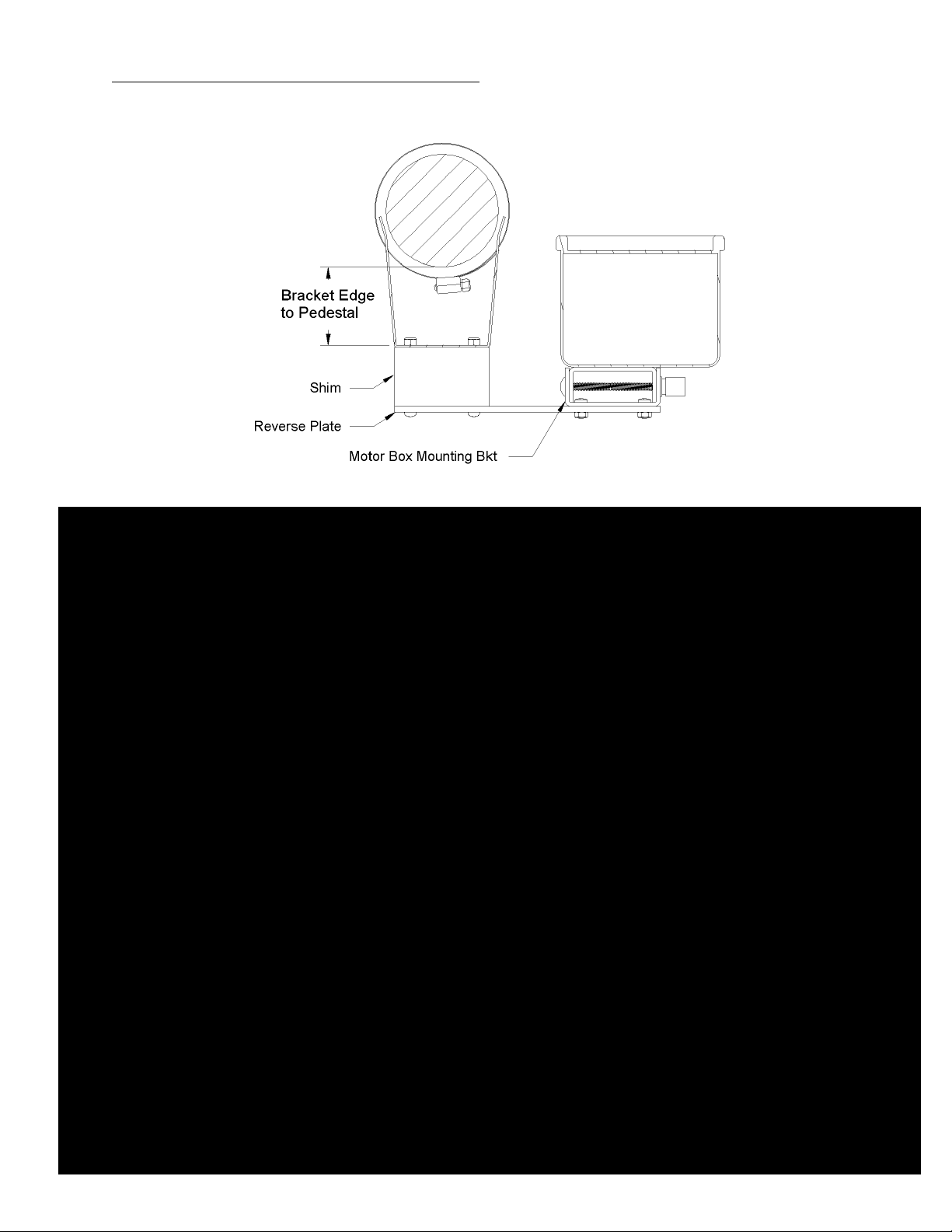
Reverse-Vertical Pedestal Mount
The motor box can be mounted to sit on either the Port or Starboard side of the
pedestal.
· If the pedestal diameter is more than 3 ¾ ʺ, the reverse plate must be at least
8 ¾ ʺ long for Port side mounting.
· If the drive pulley is inside the perimeter of the heel, 1ʺ spacers must be
used bet een the spokes and the heel pulley. Without the spacers, the drive
pulley ill hit the heel spokes hen the clutch is disengaged.
Install Motor Box onto Pedestal Bracket and Reverse Plate
1. Fasten the motor box bracket to the Reverse Plate using the four shorter #10
scre s. Fasten the Reverse Plate to the bottom of the Pedestal Bracket using
any needed shims and the four longer #10 scre s.
* If a shim is needed for aligning the belt ith the heel, it has been provided
based on the clearance bet een your spokes and pedestal (measured
5ʺ/127mm out from the heel center). Place the shim(s) bet een the reverse
plate and pedestal bracket (see diagram on follo ing page).
2. Mount the motor box onto the motor box mounting bracket using the clamp
lever, ashers and knurled thumbnut. Lock the clamping lever hen the
slotted bracket is in the middle of its adjustment range—centered in the slots.
Loosely attach Motor Box and Bracket assembly to Pedestal
1. Hang the Motor Box and Reverse Plate/Pedestal Bracket assembly from the
belt and allo it to rest against the pedestal.
2. Attach the adhesive foam pads to the hose-clamps, not the pedestal. Pass the
hose-clamps through the slots from the inside of the bracket, around the
pedestal and loosely tighten. The hose clamps should face so that they can be
tightened from the Port side.
Align belt ith heel and tighten hose-clamps
1. Adjust the clearance from the pedestal:
· For the Deep Pedestal Bracket, the belt should align ith the heel hen the top edge of the stainless bracket is
2 ½ʺ (64mm) from most pedestals using any required shims.
· For the Shallo Pedestal Bracket, the belt should align ith the heel hen the top edge of the stainless bracket
is 1ʺ (25mm) from most pedestals using any required shims.
· The bottom edge of the pedestal bracket should be ⅛ʺ – ¼ʺ closer to the pedestal than the top edge to slightly
angle the bracket.
2. Temporarily tighten the hose-clamps enough to hold the assembly in position.
3. Check for alignment: hold a yardstick or straight-edge against the back of the heel pulley; it should be fairly parallel
ith the belt hen vie ed from the side (clutch engaged; pushed in). Also look from above the heel and from the
side to be sure the motor box is square ith the heel from all directions and not at an angle. If the belt is not parallel
you can squeeze the stainless bracket deeper or shallo er onto the pedestal as needed, or add or remove a shim. If in
doubt or your heel is not uniform, favor the motor box being farther from the pedestal (rather than closer). The
slight belt slant ill pull in on the clutch hich ill help keep the clutch engaged.
4. With high heel loads or a pedestal diameter less than 4ʺ, the hose clamps may not be enough to keep the bracket in
place. In this case you may use six #10-24 x ½" scre s to fasten the pedestal bracket to the pedestal. Drill and tap the
pedestal for the scre s.
Before drilling the pedestal: test the autopilot and perform sea trials to be sure the belt size is appropriate and the
bracket is in the desired location.
CPT Autopilot Installation Manual
© 2018 CPT AUTOPILOT INC. VERSION 21 PAGE 13 OF 26
Reverse-Vertical Pedestal Mount Diagrams, Starboard Side

PAGE 14 OF 26
Reverse-Vertical Pedestal Mount Diagrams, Port Side

CPT Autopilot Installation Manual
© 2018 CPT AUTOPILOT INC. VERSION 21 PAGE 15 OF 26
L-Bracket Mount
1. Determine if the L-bracket is to mount on a side all or deck. Use
supplied bolts and nuts to attach the slotted motor box bracket so
slots ill be vertical.
2. Use the clamping lever, ashers, and knurled thumb nut to attach
the slotted motor box bracket to the fitting on back of motor box.
Lock the clamping lever hen the slotted bracket is in the middle
of its adjustment range—centered in the slots.
3. Hold motor box roughly in position, and place the belt over the
heel pulley and drive pulley. Place tape over the L-bracket
mounting area to enable marking. If any shims ill be used, tape
them to the L-bracket.
4. Position motor box so belt is snug and both pulleys are aligned. To
check for alignment, hold a yardstick or straight-edge against the
back of the heel pulley; it should be fairly parallel ith the belt
hen vie ed from the side (clutch engaged and pushed in). Also
look from above the heel and from the side to be sure the motor
box is square ith the heel from all directions and not at an
angle. If in doubt or the heel is not uniform, favor a slight belt
slant that ill help keep the clutch engaged.
5. Mark the location on side all or deck for the t o ¼˝mounting
holes and around the base of L-bracket.
6. Drill holes for ¼˝ fasteners. Drill only one hole first and check fit
before drilling the second hole.
7. Use a backing block if the mounting surface is not substantial or
trust orthy.
8. If desired, use a mounting pad bet een the L-bracket and
mounting surface to ease clamp lever operation or to permit easy
removal of the L-bracket

PAGE 16 OF 26
L-Bracket Parts Diagram
Item # Quantity Part Name
1 1 Motor Box
2 1 Drive Pulley
3 1 Motor Box Mounting Bracket, Slotted
4 1 Clamping Lever
5 1 L-Bracket
6 1 Knurled Nut ¼-20
7 2 Washer ¼"
8 4 10-24 x ⅝" Pan Head Machine Scre
9 4 10-24 nut
CPT Autopilot Installation Manual
© 2018 CPT AUTOPILOT INC. VERSION 21 PAGE 17 OF 26
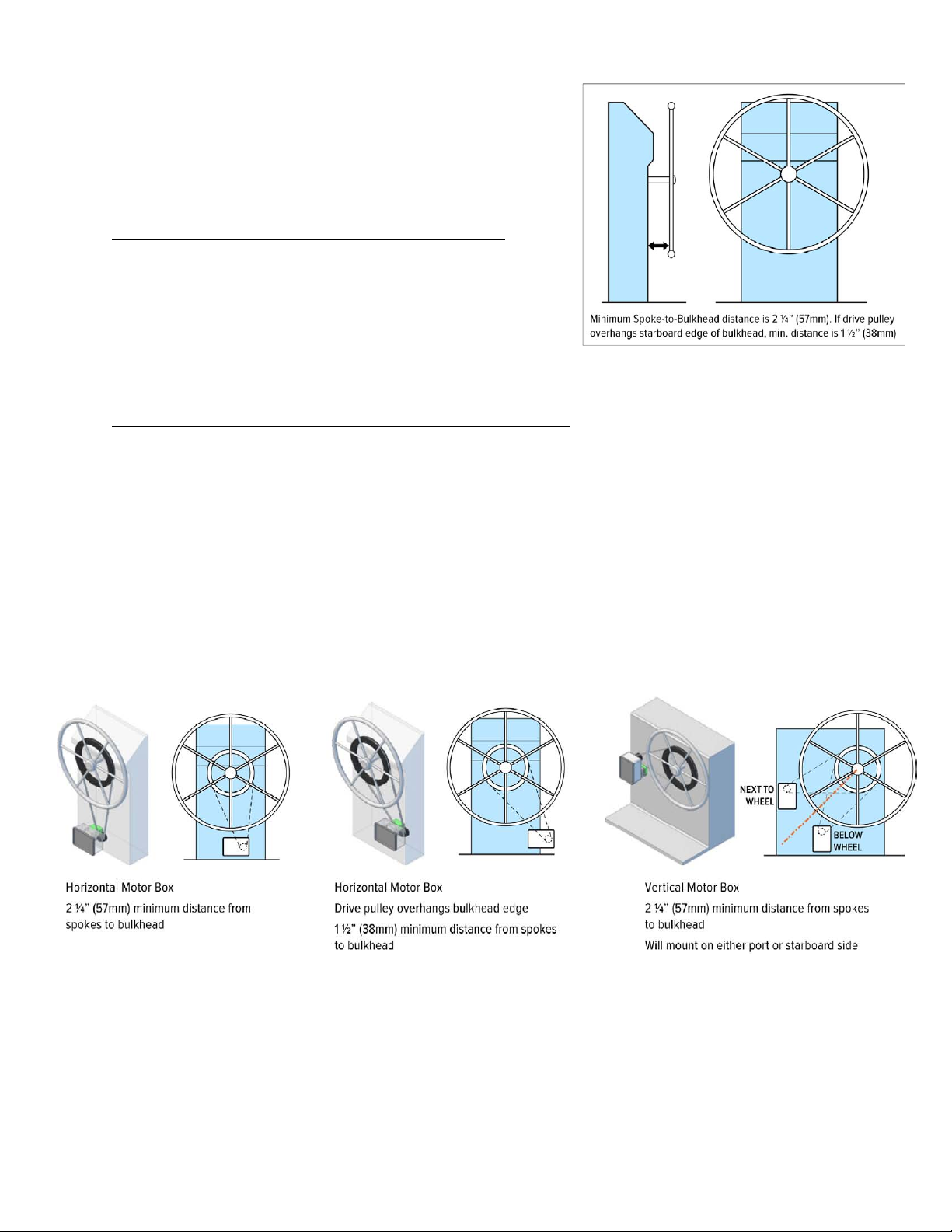
Bulkhead or Square Pedestal Mount
The motor box may be mounted to a flat surface such as a bulkhead,
console or square pedestal ithout any additional brackets. A minimum
2 ¼˝ clearance is needed bet een the heel spokes and the bulkhead to
allo room for the clutch to disengage. If the drive pulley overhangs the
edge of the bulkhead, only 1 ½˝ of clearance is needed.
Assemble Drivebox for Bulkhead or Square-Pedestal Mounting
See the “Spoke-to-Bulkhead” chart belo . If shims are required for your
installation, temporarily tape the slotted motor box bracket to the shims
ithout using the 4-machine scre s (the shims ill be flat against the
bulkhead face). Mount the taped bracket to the motor box using the
clamp lever, ashers and knurled thumb nut. Lock the clamping lever
hen the slotted bracket is in the middle of its adjustment range—
centered in the slots.
Hang Drive Box assembly from belt and let it rest firmly against bulkhead
With the belt on the heel pulley, place the drive-pulley of the motor box in the belt. Allo the motor box and shim
assembly to hang in the belt and rest snug and square against the pedestal face hile you support and position it.
Align belt ith heel & fasten mounting bracket to bulkhead
To check for alignment, vie from the side, and hold a yardstick or straight-edge against the back of the heel pulley; it
should be fairly parallel ith the belt hen vie ed from the side (clutch engaged and pushed in). If the belt is not quite
parallel ith the heel, you can remove or add a shim if needed.
Tape the bulkhead area behind the shim for marking. While holding the motor box snug and square, mark the perimeter
of the shim and slotted bracket. Remove the shim from the bracket and mark for the 4 holes on the bulkhead. Use a #10
drill for the four holes. Drill just one hole first; check the fit before drilling the remaining holes. Check the installation by
disengaging the clutch (pull out ard ¼˝) and turning the heel.
PAGE 18 OF 26
Spoke-to-Bulkhead Clearances
(If the heel pulley mounts to a ood ring on a ood heel, or to spoke spacers, use the clearance from the ood ring or
from the spoke spacers hen using the charts belo )
Full Bulkhead Mount Clearance Chart
Clearance Shim Thickness
2.25ʺ (57mm) 0.75ʺ shim (19mm)
2.375ʺ (60mm) 0.875ʺ shim (22mm)
2.5ʺ (64mm) 1ʺ shim (25mm)
2.625ʺ (67mm) 1.125ʺ shim (29mm)
2.75ʺ (70mm) 1.25ʺ shim (32mm)
2.875ʺ (73mm) 1.375ʺ shim (35mm)
3ʺ (76mm) 1.5ʺ shim (38mm)
3.125ʺ (79mm) 1.625ʺ shim (41mm)
3.25ʺ (83mm) 1.75ʺ shim (44mm)
3.375ʺ (86mm) 1.875ʺ shim (48mm)
3.5ʺ (89mm) 2ʺ shim (51mm)
3.625ʺ (92mm) 2.125ʺ shim (54mm)
3.75ʺ (95mm) 2.25ʺ shim (57mm)
3.875ʺ (98mm) 2.375ʺ shim (60mm)
4ʺ (102mm) 2.5ʺ shim (64mm)
Partial Bulkhead Mount Clearance Chart
(clutch extends past bulkhead starboard corner)
Clearance Shim Thickness
1.5ʺ (38mm) no shim
1.625ʺ (41mm) 0.125ʺ shim (3mm)
1.75ʺ (44mm) 0.25ʺ shim (6mm)
1.875ʺ (48mm) 0.375ʺ shim (10mm)
2ʺ (51mm) 0.5ʺ shim (13mm)
2.125ʺ (54mm) 0.625ʺ shim (16mm)
2.25ʺ (57mm) 0.75ʺ shim (19mm)
(refer to Full Bulkhead Mount chart for larger values)
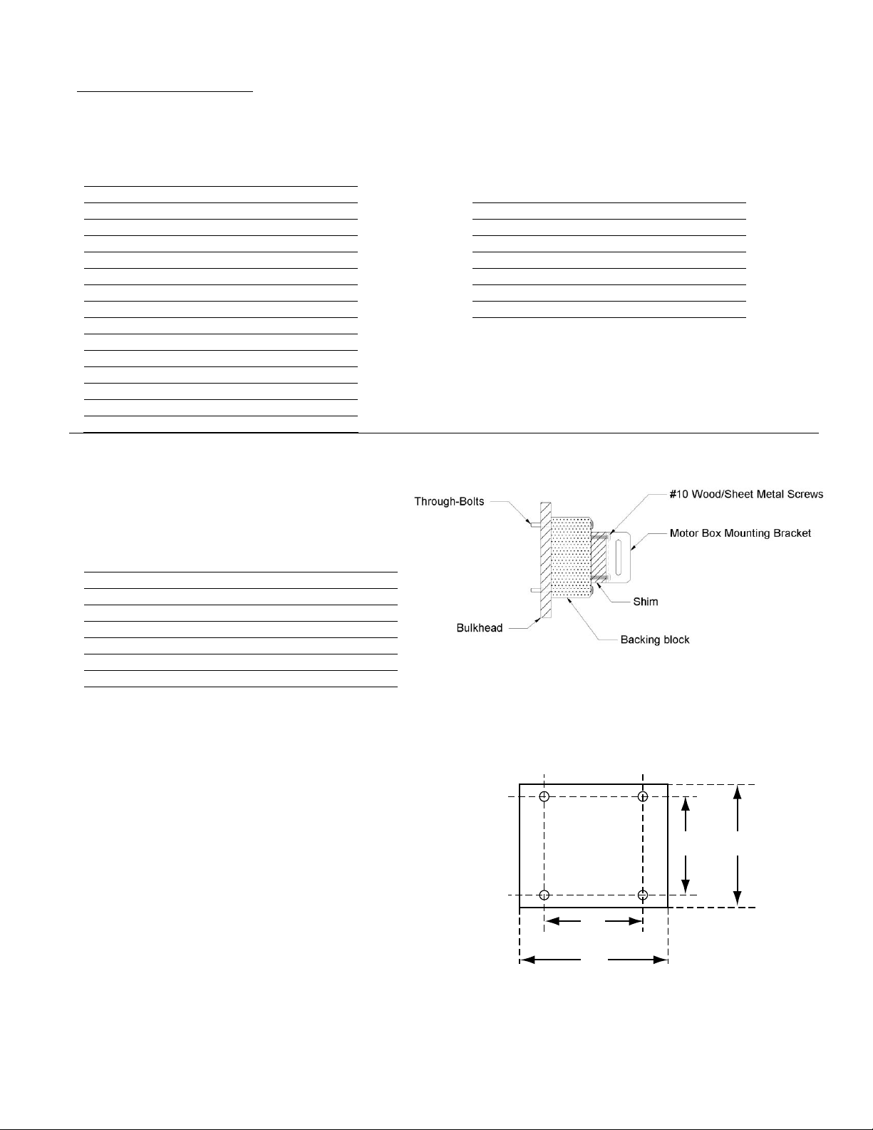
Shims thicker than 2.5ʺ are not advised due to the long
bolts required. We recommend fastening a 2ʺ backing
block to the bulkhead and attaching a thinner shim to
that in order to get the necessary clearance. See diagram
at right.
Clearance Backing Block + Shim Thickness
4.125ʺ (105mm) 2ʺ + 0.625ʺ shim (51 + 16mm)
4.25ʺ (108mm) 2ʺ + 0.75ʺ shim (51 + 19mm)
4.375ʺ (111mm) 2ʺ + 0.875ʺ shim (51 + 22mm)
4.5ʺ (114mm) 2ʺ + 1ʺ shim (51 + 25mm)
4.625ʺ (117mm) 2ʺ + 1.125ʺ shim (51 + 29mm)
4.75ʺ (121mm) 2ʺ + 1.25ʺ shim (51 + 32mm)
4.875ʺ (124mm) 2ʺ + 1.375ʺ shim (51 + 35mm)
5ʺ (127mm) 2.5ʺ + 1ʺ shim (64 + 25mm)
3"
2"
2"
2 ½"
Use #10 scre s
(#7 or 3/16ʺ drill size)
Shim Dimensions
Table of contents
Other CPT AUTOPILOT Marine Equipment manuals

Popular Marine Equipment manuals by other brands

Furuno
Furuno ETR-30N Operator's manual

Teledyne
Teledyne Pioneer DVL Getting started

Kongsberg
Kongsberg EM 2040 MKII installation manual

auto maskin
auto maskin Marine Pro 400 Series Configuration manual

VEXILAR
VEXILAR LC-8 owner's manual

Global Fire Equipment
Global Fire Equipment VALKYRIE AS IP65 quick start guide


