Veratron VMH 70 User manual

B001517
VMH 70
MARINE DISPLAY
USER MANUAL
rev. AA
EN
DE
IT
FR
ES

B001517
LANGUAGE PAGE
ENGLISH 3
DEUTSCH 47
ITALIANO 93

B001517
VMH 70
MARINE DISPLAY
USER MANUAL
rev. AA
EN
DE
IT
FR
ES

TABLE OF CONTENTS
2 B001517
TABLE OF CONTENTS
INTRODUCTION .................................................... 3
Architecture ....................................................................... 3
SAFETY INFORMATION ...................................... 4
Safety during Installation ............................................. 4
Safety after Installation ................................................. 5
Electrical Connection ................................................... 5
INSTALLATION ...................................................... 6
Before the Asse bly ..................................................... 6
Panel Mounting ................................................................ 7
ELECTRICAL CONNECTIONS ........................... 9
Engine 1 Connector [A] ................................................ 9
Engine 2 Connector [B] ............................................. 10
EasyLink Connectors [C] ........................................... 10
NMEA 2000® Connector [D].................................. 11
Video Input Connector [E] ......................................... 11
Electrical Sche atic ..................................................... 12
RPM Sensor Connection ............................................ 13
Resistive Sensor Connection .................................... 14
External Buzzer Connection (B1)............................ 14
Day / Night Mode Selector Switch (S1) ................ 14
Priority of Recieved Signals ...................................... 15
GETTING STARTED .............................................. 6
Operational Concept ................................................... 16
Standby Mode ................................................................. 16
Switching ON and OFF ............................................... 16
Menu Button Functions .............................................. 17
Touch Button Functions ............................................. 17
Calibration Wizard ......................................................... 17
Set the Day/Night Mode ............................................ 18
Startup Checklist ............................................................ 18
Upload a Custo Splash Logo ................................ 18
DATA SCREENS .................................................... 9
Screens Scrolling ............................................................ 19
Screen Layouts ................................................................ 19
Supported Data ............................................................... 21
Engine Hours .................................................................. 22
Distance Traveled ......................................................... 22
NavDash Layout ............................................................ 23
SCREENS CONFIGURATION .......................... 24
SYSTEM CONFIGURATION ............................. 26
Menu Structure ............................................................. 26
Operating the Syste Config Menu .................... 27
Units .................................................................................... 29
SAE J1939 Gateway ..................................................... 29
SENSOR CONFIGURATIONS .......................... 30
Menu Structure ............................................................. 30
Configure a Sensor Connected to the Display 31
Fuel Level Sensor Calibration ................................. 33
Other Sensors’ Calibration ....................................... 33
Custo Sensors Configuration ............................. 34
Default Calibrations .................................................... 35
Adjusting the Speed Correction Factor ............ 35
ALARMS ................................................................. 36
Menu Structure ............................................................. 36
Alar s Notification ...................................................... 36
Acknowledge an Alar ...............................................37
Active Alar s ...................................................................37
Configure a Local Alar ............................................ 38
Configure a CAN Alar ............................................. 39
TROUBLESHOOTING ........................................ 40
TECHNICAL DATA ............................................... 4
General Feature ............................................................. 41
Environ ental Features ............................................. 41
Electrical Features ........................................................ 41
Co pliance ..................................................................... 42
Supported NMEA 2000 Messages ..................... 42
Disposal Responsibility .............................................. 42
SPARE PARTS AND ACCESSORIES ............... 43

INTRODUCTION
3 B001517
INTRODUCTION
The VMH 70 is a ultifunctional display designed to onitor your boat engines and navigation.
Up to four engines can be onitored with a single display.
The integrated NMEA 2000 gateway lets you acquire engine data also via analog sensors or SAE J1939, to
then convert and distribute the on the NMEA 2000 network.
The display anages up to six resistive sensors, three voltage sensors and one digital alar .
All data are also distributed on two EasyLink channels to a axi u of 16 VMH 14 gauges per channel.
NMEA 2000 connectivity lets you view navigation data fro other devices on the network, such as
wind, co pass, GPS, speed, and depth data.
ARCHITECTURE
Following is an exa ple of an application with a VMH 70 display, used as a gateway and as a NMEA 2000
onitor.

SAFETY INFORMATION
4 B001517
SAFETY INFORMATION
WARNING
•No s oking! No open fire or heat sources!
•The product was developed, anufactured
and inspected according to the basic safety
require ents of EC Guidelines and state-of-
the-art technology.
•The instru ent is designed for use in grounded
vehicles and achines as well as in pleasure
boats, including non-classified co ercial
shipping.
•Use our product only as intended. Use of the
product for reasons other than its intended use
ay lead to personal injury, property da age
or environ ental da age. Before installation,
check the vehicle docu entation for vehicle
type and any possible special features!
•Use the asse bly plan to learn the location of
the fuel/hydraulic/co pressed air and
electrical lines!
•Note possible odifications to the vehicle,
which ust be considered during installation!
•To prevent personal injury, property da age or
environ ental da age, basic knowledge of
otor vehicle/shipbuilding electronics and
echanics is required.
•Make sure that the engine cannot start
unintentionally during installation!
•Modifications or anipulations to Veratron
products can affect safety. Consequently, you
ay not odify or anipulate the product!
•When re oving/installing seats, covers, etc.,
ensure that lines are not da aged and plug-in
connections are not loosened!
•Note all data fro other installed instru ents
with volatile electronic e ories.
SAFETY DURING INSTALLATION
•During installation, ensure that the product’s
co ponents do not affect or li it vehicle
functions. Avoid da aging these co ponents!
•Only install unda aged parts in a vehicle!
•During installation, ensure that the product
does not i pair the field of vision and that it
cannot i pact the driver’s or passenger’s head!
•A specialized technician should install the
product. If you install the product yourself,
wear appropriate work clothing. Do not wear
loose clothing, as it ay get caught in oving
parts. Protect long hair with a hair net.
•When working on the on-board electronics, do
not wear etallic or conductive jewelry such as
necklaces, bracelets, rings, etc.
•If work on a running engine is required, exercise
extre e caution. Wear only appropriate work
clothing as you are at risk of personal injury,
resulting fro being crushed or burned.
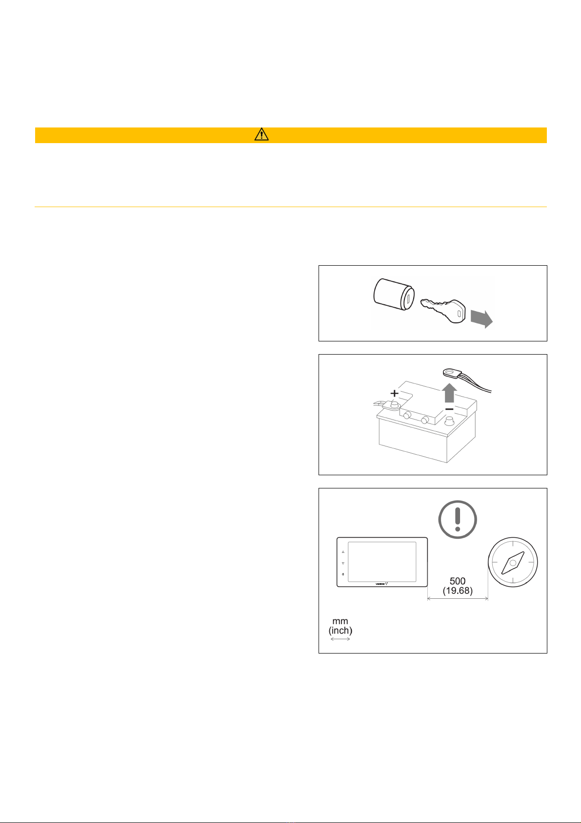
•Before beginning, disconnect the negative
ter inal on the battery, otherwise you risk a
short circuit. If the vehicle is supplied by
auxiliary batteries, you ust also disconnect
the negative ter inals on these batteries!
Short circuits can cause fires, battery
explosions and da ages to other electronic
syste s. Please note that when you disconnect
the battery, all volatile electronic e ories
lose their input values and ust be
reprogra ed.
•If working on gasoline boat otors, let the
otor co part ent fan run before beginning
work.
•Pay attention to how lines and cable harnesses
are laid so that you do not drill or saw through
the !
•Do not install the product in the echanical
and electrical airbag area!
•Do not drill holes or ports in load-bearing or
stabilizing stays or tie bars!
•When working underneath the vehicle, secure
it according to the specifications fro the
vehicle anufacturer.
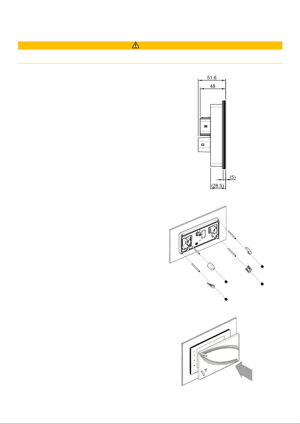
•Note the necessary clearance behind the drill
hole or port at the installation location.
Required ounting depth: 65 .

SAFETY INFORMATION
5 B001517
•Drill s all ports; enlarge and co plete the , if
necessary, using taper illing tools, saber saws,
keyhole saws or files. Deburr edges. Follow the
safety instructions of the tool anufacturer.
•Use only insulated tools, if work is necessary on
live parts.
•Use only the ulti eter or diode test la ps
provided, to easure voltages and currents in
the vehicle/ achine or boat. Use of
conventional test la ps can cause da age to
control units or other electronic syste s.
•The electrical indicator outputs and cables
connected to the ust be protected fro
direct contact and da age. The cables in use
ust have enough insulation and electric
strength and the contact points ust be safe
fro touch.
•Use appropriate easures to also protect the
electrically conductive parts on the connected
consu er fro direct contact. Laying etallic,
uninsulated cables and contacts is prohibited.
SAFETY AFTER INSTALLATION
•Connect the ground cable tightly to the
negative ter inal of the battery.
•Reenter/reprogra the volatile electronic
e ory values.
•Check all functions.
•Use only clean water to clean the co ponents.
Note the Ingress Protection (IP) ratings (IEC
60529).
ELECTRICAL CONNECTION
•Note cable cross-sectional area!
•Reducing the cable cross-sectional area leads
to higher current density, which can cause the
cable cross-sectional area in question to heat
up!
•When installing electrical cables, use the
provided cable ducts and harnesses; however,
do not run cables parallel to ignition cables or
to cables that lead to large electricity
consu ers.
•Fasten cables with cable ties or adhesive tape.
Do not run cables over oving parts. Do not
attach cables to the steering colu n!
•Ensure that cables are not subject to tensile,
co pressive or shearing forces.
•If cables are run through drill holes, protect
the using rubber sleeves or the like.
•Use only one cable stripper to strip the cable.
Adjust the stripper so that stranded wires are
not da aged or separated.
•Use only a soft soldering process or
co ercially available cri p connector to
solder new cable connections!
•Make cri p connections with cable cri ping
pliers only. Follow the safety instructions of the
tool anufacturer.
•Insulate exposed stranded wires to prevent
short circuits.
•Caution: Risk of short circuit if junctions are
faulty or cables are da aged.
•Short circuits in the vehicle network can cause
fires, battery explosions and da ages to other
electronic syste s. Consequently, all power
supply cable connections ust be provided
with weldable connectors and be sufficiently
insulated.
•Ensure ground connections are sound.
•Faulty connections can cause short circuits.
Only connect cables according to the electrical
wiring diagra .
•
If operating the instru ent on power supply
units, note that the power supply unit ust be
stabilized and it ust co ply with the following
standard: DIN EN 61000, Parts 6-1 to 6-4.

INSTALLATION
6 B001517
INSTALLATION
WARNING
Before
starting work, disconnect the negative ter inal of the battery to avoid the risk of a short circuit. If
the vehicle is equipped with additional batteries, the negative ter inal of all batteries ust also be
disconnected if necessary. Short circuits can burn cables, explode batteries and cause da age to other
electronic syste s. Re e ber that by disconnecting the battery, all data entered in the te porary
electronic e ory will be lost and will have to be reprogra ed.
BEFORE THE ASSEMBLY
1. Before starting work, switch off the ignition and
re ove the ignition key. If necessary, re ove the
ain power switch.
2. Disconnect the negative ter inal of the battery.
Do not allow the battery to be reconnected by
istake.
3. When ounting the device in the vicinity of a
agnetic co pass, aintain a protective distance
fro the co pass.
4. If required for the syste , purchase an NMEA
2000 drop cable with five-pin M12 connector ( ax
drop cable length 6 ) and a video cable with a
co patible four-pin M12 connector
(A2C1845710001).
These are not included.

INSTALLATION
7 B001517
PANEL MOUNTING
WARNING
•Do not drill holes or installation openings in supporting or stabilizing bea s!
•The ounting location ust have sufficient clearance behind the ounting holes or openings.
1. Make a rectangular hole in the panel using
the drilling te plate (see next page of this
docu ent) and considering the device
di ensions [A].
2. Turn in the four grub screws of the
installation kit on the backside of the device
3. Thread the cables through the hole and
connect the connectors.
NOTE: screw in M12 connectors with care. If
they screw with difficulty, re ove and screw
the back in.
4. Insert the device fro the front and tighten
the four nuts on top of the plastic cla ps to
pull the display towards the panel [B].
5. Re ove the protection fil fro the display
and ake sure it is clean and dry.
6. Install the sun cover in front of the display
by placing it onto it and pressing it on the
lateral sides with your fingers to cla p it.
A
B
C

INSTALLATION
8 B001517

ELECTRICAL CONNECTIONS
9 B001517
ELECTRICAL CONNECTIONS
WARNING
•
Refer to the safety rules described in the electrical connections section of the safety infor ation
chapter of this docu ent!
ENGINE CONNECTOR [A]
Pin No.
Wire color Description
1 Red KL. 30 – Battery power 12 / 24 V
2 Black KL. 31 - Ground
3 White Alar output
4 Green Frequency sensor signal - RPM
5 Blue SAE J1939 – CAN High
6 Blue / White SAE J1939 – CAN Low
7 Yellow KL. 15 – Ignition positive
8 Grey Resistive sensor input
9 Brown Resistive sensor input
10 Orange 0-5 V sensor input
11 Light Blue 4-20 A sensor input
12 Violet 4-20 A sensor input
Molex MX150 12-poles connector, cable view
and wire harness A2C1507870001
(included)

ELECTRICAL CONNECTIONS
10 B001517
ENGINE 2 CONNECTOR [B]
Pin No. Wire color Description
1 Pink Configurable alar input
2 Black KL. 31 - Ground
3 White Alar output
4 Green Frequency sensor signal - RPM
5 Blue SAE J1939 – CAN High
6 Blue / White SAE J1939 – CAN Low
7 Yellow 0-5 V sensor input
8 Grey Resistive sensor input
9 Brown Resistive sensor input
10 Orange 0-5 V sensor input
11 Light Blue Resistive sensor input
12 Violet Resistive sensor input
Molex MX150 12-poles connector, cable view
and wire harness A2C1507870001 (included)
EASYLINK CONNECTORS [C]
Pin No. Description
1 +12V Power
2 GND
3 EasyLink Data
The EasyLink interface is eant for connecting VMH 14
satellites.
It is possible to connect up to 16 gauges per channel
(daisy-chain) as shown in the picture on the right.
Each channel can display the data fro one engine.
The engine displayed can be configured in [SYSTEM
CONFIGURATIONS] >[EASYLINK].
OceanLink satellites are not supported.
AMP SuperSeal 1.5 3 poles plug
fe ale, cable view

ELECTRICAL CONNECTIONS
11 B001517
NMEA 2000® CONNECTOR [D]
Pin No. Description
1 Shield
2 NET-S (V+)
3 NET-C (V-)
4 NET-H (CAN High)
5 NET-L (CAN Low)
Micro-C M12 5 poles plug
ale, cable view
Once the installation is co plete, you can interface the device to the
NMEA 2000® network through the dedicated connector [D].
Be sure to tighten the M12 connector by screwing it onto its counterpart
in order to preserve its watertightness.
An accessory drop cable is required. (Not included)
Note that NMEA 2000® does not allow drop cables longer than 6
eters.
Refer to the NMEA 2000® standard for proper network design.
VIDEO INPUT CONNECTOR [E]
Pin No. Description
1 Video input 2
2 Video input 1
3 GND 2
4 GND 1
M12 4 poles plug
fe ale, cable view

ELECTRICAL CONNECTIONS
12
B001517
ELECTRICAL SCHEMATIC
Designations in the circuit diagram
Batt - Ter .30 – Battery Power 12/24 V
IGN - Ter . 15 - Ignition positive
GND - Ter . 31 - Ground
Illum. - Ter .58 – Illu ination positive
S - Day/Night ode switch (not included)
S2 - Ignition key
F - 3A fuse (not included)
B /B2 – External acoustic alar (not included)
RES - Resistive inputs
RPM - Frequency inputs
ALARM – External digital alar
J 939 – SAE J1939 CAN ports

ELECTRICAL CONNECTIONS
13 B001517
RPM SENSOR CONNECTION
The engine RPM signal can be obtained fro different sources, respectively the alternator “W” ter inal, the
ignition coil ter inal “1”, or fro dedicated sensors such as a generator or an inductive sensor.
It is advisable to use sensors with isolated ground, and it is necessary to ensure that the sensor ground is
connected to the display ground to avoid incorrect readings.

ELECTRICAL CONNECTIONS
14 B001517
RESISTIVE SENSOR CONNECTION
Any sensor connected to a resistive input of the display ust be connected as shown in the figure.
It is advisable to use sensors with isolated ground, and it is necessary to ensure that the sensor ground is
connected to the display ground to avoid incorrect readings.
Tank level sensor connected
to resistive input 8
Te perature sensor with isolated ground
connected to resistive input 9
Pressure sensor with isolated ground
connected to resistive input 8
EXTERNAL BUZZER CONNECTION (B )
The display supports the connection of
two
external
alar s
(B1/B2) via the dedicated alar outputs.
This buzzer/la p can be powered at different voltages
(consult the buzzer anufacturer's anual), as the alar
output is connected to ground inside the display. (Open
collector output)
It is i portant to note that the axi u current supported is
500 A.
DAY / NIGHT MODE SELECTOR SWITCH (S )
The display allows you to set two display illu ination levels, one for day and night.
It is possible to switch between day and night ode by eans of a switch external to the display (S1)
connected to the power supply (KL.30), or by connecting to the lights signal onboard KL.58, if present.
Every 0-5V input of the display can be configured for this purpose (see “Sensors’ configuration”).
To set the desired ode, act on the selected illu ination input pin on the MX150 connector as follows:
To set the mode...
Then...
day
ove the pin switch to
GND/OPEN
.
night
ove the pin switch to
BATTERY PLUS
.
In the sensor settings the function of the according voltage input ust be defined as illu ination input.

ELECTRICAL CONNECTIONS
15 B001517
PRIORITY OF RECIEVED SIGNALS
If the sa e data is available fro ore than one source for the sa e engine, the received signal priority
is the following:
•Analog input
•SAE J1939
•NMEA 2000

GETTING STARTED
16 B001517
GETTING STARTED
OPERATIONAL CONCEPT
During nor al operation the display shows one out of the up to ten custo izable data pages. Swipe the
touchscreen to the left or right to scroll through these pages.
To access the VMH 70 enu, press the field MENU in the screens lower left
corner. This button leads to the ain enu fro where there are four sub- enus:
•System Configuration
Change the syste para eters like brightness, units or ti e.
•Screen Configuration
Delete pages, add new ones or personalize the data to be displayed on the current ones.
•Alarms
See the active alar s and define the settings for when an alar should be displayed, sent out or
trigger the external buzzer.
•Sensor Configuration
Define all the settings for the analog inputs.
For ore infor ation on these enus refer to the respective chapters of this docu ent.
The display brightness can be changed at any ti e by pushing the arrow buttons on the left side of the
device.
STANDBY MODE
The VMH 70 display supports a standby ode, where the display is si ply shut off to either
reduce the current consu ption or just to turn off the illu inated display in dark conditions
when not needed.
Please note that during standby ode the unit is totally operative, and it can be instantly
turned back on.
To activate the standby ode, just press the touch button with the power sy bol.
SWITCHING ON AND OFF
The on/off ode depends on the ignition signal on ter inal 15 (connected to Engine1 connector, pin 7 –
yellow wire).
At power up, logo and software version followed by a security essage appear followed by the last data
page viewed before turned off.
While the VMH 70 is turned on, it can be put into standby ode as described above.
You can custo ize the loading i age displayed at power up using the Veratron Configuration Tool.
Contact your Veratron dealer for ore infor ation.

GETTING STARTED
17 B001517
MENU BUTTON FUNCTIONS
When operating the enu these buttons will be displayed on the right edge of the display. Use the to
navigate through the enu. It is not possible to scroll the enu by swiping the list.
Button
Name Function
BACK •Return to the previous enu
UP
DOWN •Scroll options
ENTER •Open a sub- enu
•Confir the selection
TOUCH BUTTON FUNCTIONS
The following touch buttons are incorporated into the glass on the left of the screen. While the data screens
are displayed the buttons serve the following functions:
Button
Name Function
UP
DOWN •Change illu ination brightness
STANDBY
•Push this button to bring the display in the standby ode or to
start it up after being in standby.
(Only works if the ignition signal is turned on as well.)
CALIBRATION WIZARD
The Calibration wizard appears when first turned on after reset and every ti e turned on until sensors are
calibrated.
The display pro pts you to configure your sensors.
Choose [Yes], to open enu SENSOR CONFIG.
Choose [No], to display the first default data page and configure the sensors later.

GETTING STARTED
18 B001517
SET THE DAY/NIGHT MODE
There are three ways to steer the display to be in day- or night ode:
•Illumination input
Define one of the 0-5Volt analog inputs to be an illu ination input and connect it to an external
switch or to the vessel’s illu ination signal. For ore infor ation on the installation see chapter “Day
/ Night Mode Selector Switch (S1)” in the section “Electrical Connections”.
•Light sensor
Enable the built-in light sensor in [SYSTEM CONFIGURATION]>[DISPLAY]>[Auto Day/Night
Switch] so the display auto atically toggles between day and night ode depending on the
surroundings brightness.
•Manually through menu
To anually switch between the different odes, ake a selection in the enu [SYSTEM
CONFIGURATION]>[DISPLAY]>[ILLUMINATION MODE].
STARTUP CHECKLIST
Following are the steps for initial configuration:
1. Connect any sensors to analog inputs.
2. When turned on, read the security essage, then select [Yes] to open the enu SENSOR
CONFIGURATION and define the sensors para eters (see "Sensor configuration").
3. Set up general device operations (see "Syste settings").
4. Add/re ove data pages selecting the best layout and data to be viewed (see "Data page
configuration").
5. If a page layout with bar graphs is used, custo ize the ini u and axi u intervals (Bar graph
settings, see "Syste settings").
6. Enable/disable local, NMEA 2000 and J1939 alar s (see "Alar anage ent").
UPLOAD A CUSTOM SPLASH LOGO
A custo splash logo can be loaded fro a PC using the Veratron Configuration Tool. That logo will be
displayed each ti e during the startup process.
For ore infor ation, please refer to the Veratron Configuration Tool user anual or contact your Veratron
reseller.
Table of contents
Languages:
Other Veratron Marine Equipment manuals
Popular Marine Equipment manuals by other brands

Bosch
Bosch FNM-420V-A-WH installation guide

Side-Power
Side-Power Stabilizer Operation and user's guide

WÄRTSILÄ
WÄRTSILÄ RadaScan RESPONDERS 3 Series user guide

Boss Audio Systems
Boss Audio Systems MR1420W user manual

BRNKL
BRNKL archipelago LIME LSGI1021 Setup guide

Faria
Faria SmartCraft MG2000 Quick reference card

Parker
Parker Sea Recovery ULTROClear Series Installation operation & maintenance

E2S
E2S IS-pA1 instruction manual

MIVARDI
MIVARDI MX33 user manual

Furuno
Furuno FE-700 installation manual

ESP
ESP MAGDUO MAGDUOSRSQ Installation and maintenance instructions

Vetus
Vetus EC3 Operation manual and installation instructions