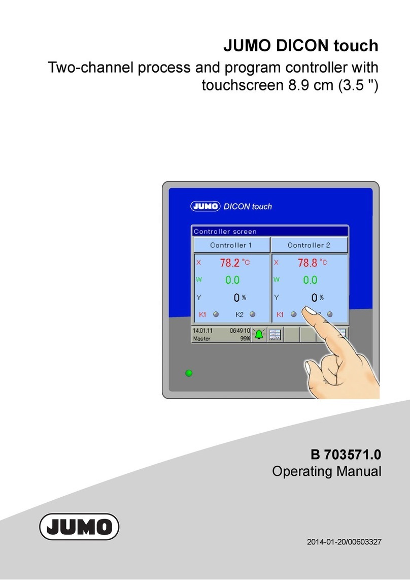
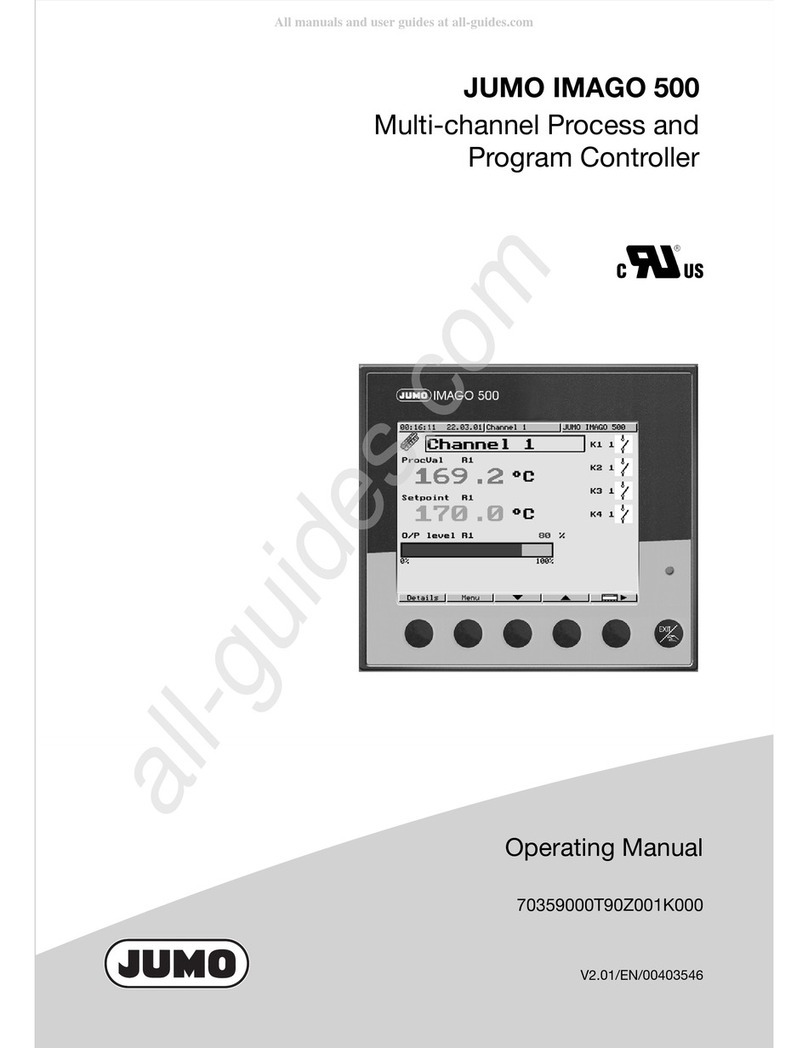
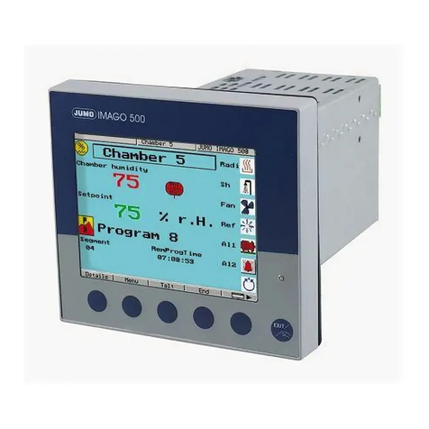
JUMO IMAGO 500 User manual

JIMAGO 500
Multi-channel process and
program controller
B 70.3590.2
Interface Description
05.02/00403594


Contents
1 Introduction 5
1.1 Preface .......................................................................................................... 5
1.2 Typographical conventions ......................................................................... 6
1.2.1 Warning signs ................................................................................................. 6
1.2.2 Note signs ...................................................................................................... 6
1.2.3 Representation ............................................................................................... 6
2 Protocol description 7
2.1 Master-slave principle ................................................................................. 7
2.2 Transmission mode (RTU) ........................................................................... 7
2.3 Device address ............................................................................................. 8
2.4 Timing of the communication ..................................................................... 8
2.4.1 Timing of a data request .............................................................................. 10
2.4.2 Communication during the internal processing time of the slave ................ 11
2.4.3 Communication during the response time of the slave ............................... 11
2.5 Structure of the data blocks ...................................................................... 11
2.6 Error handling ............................................................................................. 11
2.7 Checksum (CRC16) .................................................................................... 13
2.8 Interface ...................................................................................................... 14
3 Functions 15
3.1 Read n words .............................................................................................. 15
3.2 Write one word ........................................................................................... 16
3.3 Write n words .............................................................................................. 17

Contents
4 Data flow 19
5 Address tables 21
5.1 Process data ............................................................................................... 21
5.2 Setpoints ..................................................................................................... 25
5.3 Manual output ............................................................................................. 25
5.4 Controller parameter ................................................................................. 26
5.5 Program start with start data .................................................................... 29
5.6 Manual operating mode with manual data .............................................. 30
5.7 Program transmission ............................................................................... 30
5.8 Commands .................................................................................................. 31
5.9 Frequent setpoint programming ............................................................... 33
5.10 Process value via interface ....................................................................... 34
5.11 Device identification .................................................................................. 34
5.12 Setting the clock ........................................................................................ 35
6 Program example 37

5
1 Introduction
1.1 Preface
Please read these Operating Instructions before commissioning the interface.
Keep the manual in a place that is accessible to all users at all times.
Please assist us to improve these operating instructions, where necessary.
Your suggestions will be appreciated.
Phone +49 6616003-0
Fax +49 661 6003-607
HAll the necessary information for operating the interface is
contained in these operating instructions. However, if any
difficulties should still arise during start-up, please do not carry out
any unauthorized manipulations. You could endanger your rights
under the instrument warranty!
Please contact the nearest subsidiary or the main factory in such a
case.
EWhen returning modules, assemblies or components, the
regulations of EN 100 015 “Protection of electrostatically sensitive
components” must be observed. Use only the appropriate ESD
packaging for transport.
Please note that we cannot accept any liability for damage caused
by ESD (electrostatic discharge).

1 Introduction
6
1.2 Typographical conventions
1.2.1 Warning signs
The symbols for Danger and Caution are used in these operating instructions
under the following conditions:
1.2.2 Note signs
1.2.3 Representation
VDanger This symbol is used when there may be danger to personnel
if the instructions are ignored or not followed correctly!
!Caution This symbol is used when there may be damage to
equipment or data if the instructions are ignored or not
followed correctly!
ECaution This symbol is used where special care is required when
handling components liable to damage through electrostatic
discharge.
"Info This symbol is used when your special attention is drawn to a
remark.
#Reference This symbol refers to further information in other manuals,
chapters or sections.
abc1Footnote Footnotes are remarks that refer to specific points in the text.
Footnotes consist of two parts:
A marker in the text, and the footnote text.
The markers in the text are arranged as continuous superscript
numbers.
The footnote text (in smaller typeface) is placed at the bottom
of the page and starts with a number and a full stop.
0x0010 Hexadecimal
number
A hexadecimal number is identified by being preceded by an
“0x” (here: 16 decimal).

7
2 Protocol description
2.1 Master-slave principle
The communication between a PC (master) and a device (slave) using
MODbus takes place according to the master-slave principle, in the form of a
data request/instruction - response.
The master controls the data exchange, the slaves only have a response
function. They are identified by their device address.
2.2 Transmission mode (RTU)
The transmission mode used is the RTU mode (Remote Terminal Unit). Data
are transmitted in binary format (hexadecimal) with 8 bits. The LSB (least
significant bit) is transmitted first. The ASCII operating mode is not supported.
Data format
The data format describes the structure of a character transmitted. The
following format options are available:
Master
Slave 1 Slave 2 Slave n
Data word Parity bit Stop bit
1/2 bit
Bit number
8 bit — 1 9
8 bit even 1 10
8 bit odd 1 10
8 bit — 2 10

2 Protocol description
8
2.3 Device address
The device address of the slave can be set between 0 and 254. Address 0 is
reserved.
Two forms of data exchange can be distinguished:
Query Data request/instruction by the master to a slave, via the corresponding
device address.
The slave addressed responds.
Broadcast Instruction by the master to all slaves, via the device address 0. The
connected slaves do not respond. A specific setpoint can, for example, be
transmitted to all slaves. In such a case, the correct acceptance of the values
by the slaves should be checked by a subsequent readout of the setpoint.
A data request with device address 0 is not meaningful.
2.4 Timing of the communication
Start and end of a data block are marked by transmission pauses. The
maximum permitted interval between two consecutive characters is three
times the transmission time of a single character.
The character transmission time (the time taken to transmit one character)
depends on the baud rate and the data format that is used (stop bits and
parity bit).
For a data format with 8 data bits, no parity bit and one stop bit, this is:
character transmission time [msec] = 1000 * 9 bits/(baud rate)
For the other data formats it is:
character transmission time [msec]
= 1000 * (8 bits+parity bit+stop bit(s)) bits/(baud rate)
Sequence
HA maximum of 31 slaves can be addressed via the RS422/485
interface.
Data request from master
transmission time = n characters * 1000 * x bits/(baud rate)
Marker for end of data request
3 characters * 1000 * x bits/(baud rate)
Processing of the data request by the slave (max. 250msec)
Response of slave
transmission time = n characters * 1000 * x bits/(baud rate)
Marker for end of response
3 characters * 1000 * x bits/(baud rate)

9
2 Protocol description
Example Marker for end of data request or end of response for 10/9 bit data format
Waiting time = 3 characters * 1000 * 10 bits/(baud rate)
Baud rate [baud] Data format [bit] Waiting time [msec]
(3 characters)
38400 10 0.79
90.71
19200 10 1.57
91.41
9600 10 3.13
92.82

2 Protocol description
10
2.4.1 Timing of a data request
Timing scheme A data request runs according to the following timing scheme:
t0End marker = 3 characters
(the time depends on the baud rate)
t1This time depends on the internal processing.
The maximum processing time is 250 msec.
The minimum response time which can be set is required by the RS485
interface in the master, in order to switch over the interface driver from
transmit to receive. This parameter is not required for the RS422 interface.
t2This time is needed by the controller, to switch over from transmit back to
receive. This is the waiting time which the master has to observe before
presenting a new data request. This time must always be observed, even
when the new data request is directed to a different device.
RS422 interface: t2= 1msec
RS485 interface: t2= 10msec
HA minimum response time can be set in the controller, under the
menu item “Interface”. This preset time is the minimum time which
will be waited before an answer is transmitted (0 — 500 msec). If a
smaller value is set, then the response time may be longer than the
preset value (because the internal processing time is longer), the
controller answers as soon as the internal processing is
completed. A preset time of 0 msec means that the controller
answers with the maximum possible speed.
DatenanfrageMaster
Slave
t
Datenanfrage
Antwort
t2
t0t1t0
Data request Data request
Response

11
2 Protocol description
2.4.2 Communication during the internal processing time of the slave
No data requests from the master are permitted during the internal processing
time. Any data requests that are made during this period will be ignored by the
slave.
2.4.3 Communication during the response time of the slave
No data requests from the master are permitted during the response time of
the slave. Any data requests that are made during this period will result in the
invalidation of all the data currently on the bus.
2.5 Structure of the data blocks
All data blocks have the same structure:
Data structure
Each data block contains four fields:
Slave address device address of a specific slave
Function code Function selection (read, write words)
Data field contains the information:
- word address
- word number
- word value
Checksum detection of transmission errors
2.6 Error handling
Error codes There are three error codes:
1invalidfunction
2 invalid parameter address
8 write access to parameter denied
Slave
address
Function
code
Data field Checksum
CRC16
1 byte 1 byte x byte(s) 2 bytes

2 Protocol description
12
Response in
the event of an
error
The function code is ORed with 0x80, which means that the MSB (most
significant bit) is set to 1.
Example Data request:
Response:
Special cases The slave will not respond in the following error situations:
- the checksum (CRC16) is not correct
- the instruction from the master is incomplete or over-defined
- the number of words or bits to be read is zero
Slave
address
Function
XX OR 80h
Error code Checksum
CRC16
1 byte 1 byte 1 byte 2 bytes
01 03 40 00 00 04 CRC16
01 83 02 CRC16

13
2 Protocol description
2.7 Checksum (CRC16)
The checksum (CRC16) serves to recognize transmission errors. If an error is
identified during evaluation, the corresponding device does not respond.
Calculation
scheme
Example Data request: Read two words, starting at address 0x00CE
(CRC16 = 0xA592)
Response: (CRC16 = 0xADF5)
CRC = 0xFFFF
CRC = CRC XOR ByteOfMessage
For (1 to 8)
CRC = SHR(CRC)
if (flag shifted right = 1)
then else
CRC = CRC XOR
0xA001
while (not all ByteOfMessage processed);
07 03 00 CE 00 02 A5 92
CRC16
07 03 04 00 00 41 C8 AD F5
Wo r d 1 Wo r d 2 C R C 1 6

2 Protocol description
14
2.8 Interface
MODbus
➔
Value/selection Description
Protocol MODBUS
MODBUS int.
MODbus integer:
All values are transmitted in the integer format
Baud rate 9600
19200
38400
Data format 8-1-none
8-1-odd
8-1-even
8-2-none
(Data bits)-(stop bits)-(parity)
Device address 0—1— 254 Address in data network
Minimum
response time
0— 500msec Minimum time that elapses between the request of a device
in the data network and the response of the controller.
Factory settings are shown bold.

15
3 Functions
The following functions are available for the device:
3.1 Read n words
This function reads n words, starting from a defined address.
Data request
Response
Example Read the two setpoints of controller 1
Word address = 0x083C (setpoint W1)
Data request:
Response:
Function number Function
0x03/0x04 read n words
0x06 write one word
0x10 write n words
Slave
address
Function
0x03 or 0x04
Address
first word
Word
number
(max. 127)
Checksum
CRC16
1 byte 1 byte 2 bytes 2 bytes 2 bytes
Slave
address
Function
0x03 or 0x04
Number
of bytes
read
Word
value(s)
Checksum
CRC16
1 byte 1 byte 1 byte x byte(s) 2 bytes
07 03 08 3C 00 04 8603
07 03 08 0000 41C8 0000 4120 5416
Setpoint 1
(25.0)
Setpoint 2
(10.0)

3 Functions
16
3.2 Write one word
For the “write word” function, the data blocks for instruction and response are
identical.
Instruction
Response
Example Write limit value for limit comparator 1 = 275
Word address = 0x026F
Instruction: Write first part of the value
Response (as instruction):
Instruction: Write second part of the value
Response (as instruction):
Slave
address
Function
0x06
Word address Word value Checksum
CRC16
1 byte 1 byte 2 bytes 2 bytes 2 bytes
Slave
address
Function
0x06
Word address Word value Checksum
CRC16
1 byte 1 byte 2 bytes 2 bytes 2 bytes
07 06 02 6F 80 00 D9C9
07 06 02 70 43 89 7959
07 06 02 70 43 89 7959

17
3 Functions
3.3 Write n words
Instruction
Response
Example Write reset time Tn1 = 20sec of the first parameter set
Word address = 0x0866
Instruction:
Response:
Slave
address
Function
0x10
Address
of first
word
Word
number
(max.
127)
Byte
number
Word
value(s)
Checksum
CRC16
1 byte 1 byte 2 bytes 2 bytes 1 byte x byte(s) 2 bytes
Slave
address
Function
0x10
Address
of first word
Word
number
Checksum
CRC16
1 byte 1 byte 2 bytes 2 bytes 2 bytes
07 10 08 66 00 02 04 00 00 41 A0 3CCD
07 10 08 66 00 02 A3D1

3 Functions
18

19
4 Data flow
All process values (variables) together with their addresses, data type and
access mode are described below.
References are as follows:
R/O read access only
R/W read and write access
char, byte byte (8 bits)
int integer (16 bits)
Bit x bit No. x
long long integer (4 bytes)
float float value (4 bytes) according to IEEE 754
Byte sequence Because of the platform-dependent representation of floating-point numbers
and long values, the bytes must be arranged in the sequence that is
appropriate for MODbus.
Please find out in which sequence float values are stored in your system (PC,
PLC etc.).
Single-float format (32bit) according to the IEEE 754 standard
S - sign bit
E - exponent (complement to base 2)
M - 23bit normalized mantissa
MODbus-float format
HThe RS422/485 interface is inactive during communication
via the setup interface.
SEEEEEEE EMMMMMMM MMMMMMMM MMMMMMMM
MODbus address x MODbus address x+1
MMMMMMMM MMMMMMMM SEEEEEEE EMMMMMMM

4 Data flow
20
Example: Transmission of the floating-point number 3000
Long values
Example: Transmission of the number 66051
PC (master): 00 80 3B 45
MODbus: 8000453B
Byte 1234
PC(master): 03020100
MODbus: 00010203
Byte 1234
Other manuals for IMAGO 500
3
Table of contents
Other JUMO Controllers manuals

JUMO
JUMO IMAGO 500 User manual

JUMO
JUMO exTHERM-DR User manual

JUMO
JUMO B 703571.0 User manual

JUMO
JUMO iTRON DR 100 User manual

JUMO
JUMO DICON touch User manual
JUMO
JUMO AQUIS 500 AS User manual

JUMO
JUMO eTron M 100 User manual

JUMO
JUMO diraTRON 104 Reference guide

JUMO
JUMO TYA S202 User manual

JUMO
JUMO diraTRON 104 User manual

JUMO
JUMO DICON touch User manual

JUMO
JUMO AQUIS 500 pH User manual

JUMO
JUMO IMAGO 500 User manual

JUMO
JUMO cTRON 04 User manual

JUMO
JUMO iTRON04 User manual

JUMO
JUMO Quantrol LC200 User manual

JUMO
JUMO DICON 400 User manual

JUMO
JUMO dTRON 304 User manual

JUMO
JUMO DICON 401 User manual

JUMO
JUMO cTRON 04 User manual