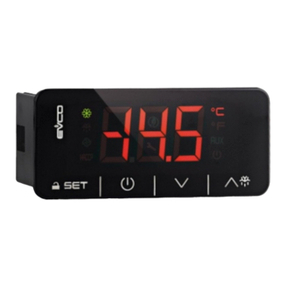
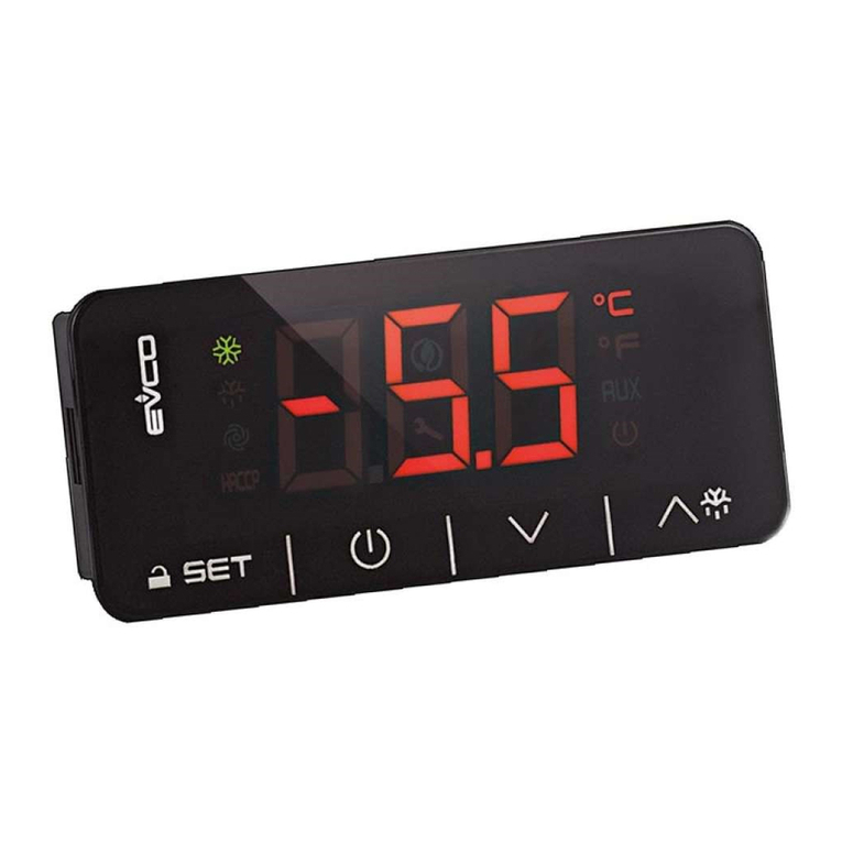
Evco EV3 HRV Instructions for use

EVCO S.p.A.
EV3 HRV & EVD HRV | Application manual ver. 1.0a | Code 1443DHRVE104
pa e 1 of 74
EV3 HRV & EVD HRV
Controllers for mechanical ventilation
units for air renewal and
heat recovery
Application manual ver. 1.0a February 2020 | EN LISH
Code 1443DHRVE104

EVCO S.p.A.
EV3 HRV & EVD HRV | Application manual ver. 1.0a | Code 1443DHRVE104
pa e 2 of 74
Important
Read this manual carefully before installation and before usin the devices and take all the prescribed precautions. Keep this manual
with the devices for future consultation.
Only use the devices in the ways described in this manual. Do not use these devices as safety devices.
Disposal
The devices must be disposed of accordin to local re ulations overnin the collection of electrical and electronic waste.
In accordance with the Declaration of Conformity to the EU R&TTE Directive, model EVJ LCD with a built-in Bluetooth low ener y sensor
may be used in the followin nations: Austria, Bel ium, Cyprus, the Czech Republic, Denmark, Estonia, Finland, France, Germany,
Greece, Hun ary, Ireland, Italy, Latvia, Lithuania, Luxembur , Malta, Norway, Poland, Portu al, Slovakia, Slovenia, Spain, Sweden,
Switzerland, the Netherlands and the United Kin dom.

EVCO S.p.A.
EV3 HRV & EVD HRV | Application manual ver. 1.0a | Code 1443DHRVE104
pa e 3 of 74
SUMMARY
1 INTRODUCTION ...................................................................................................................................... 5
1.1 Models available, purchasin codes and technical features ..................................................................... 5
2 DESCRIPTION ......................................................................................................................................... 7
2.1 Description of EV3 HRV ..................................................................................................................... 7
2.2 Description of EVD HRV ..................................................................................................................... 8
2.3 Description of EV3K11 ....................................................................................................................... 9
2.4 Description of EVJ LCD .................................................................................................................... 10
3 MEASUREMENTS AND INSTALLATION ...................................................................................................... 11
3.1 Measurements and installation of EV3 HRV ........................................................................................ 11
3.2 Measurements and installation of EVD HRV ........................................................................................ 11
3.3 Measurements and installation of EV3K11 .......................................................................................... 12
3.4 Measurements and installation of EVJ LCD ......................................................................................... 13
3.4.1 Models for wall mountin ....................................................................................................... 13
3.4.2 Models for wall mountin with back-slot for flush mountin box ................................................. 13
3.5 Installation precautions ................................................................................................................... 14
4 USER INTERFACE .................................................................................................................................. 15
4.1 Key functions ................................................................................................................................. 15
4.2 Display .......................................................................................................................................... 16
4.2.1 HOME PAGE ......................................................................................................................... 16
4.2.2 Icons .................................................................................................................................. 16
4.3 LED EVD HRV ................................................................................................................................. 19
5 ELECTRICAL CONNECTION ..................................................................................................................... 20
5.1 Example of EV3 HRV electrical connection .......................................................................................... 20
5.2 Example of EVD HRV electrical connection ......................................................................................... 21
5.3 Example 1 of EV3K11 electrical connection ........................................................................................ 22
5.4 Example of EVJ LCD electrical connection ........................................................................................... 23
5.4.1 Models for wall mountin ....................................................................................................... 23
5.4.2 Models for wall mountin with back-slot for in-wall box ............................................................. 25
5.5 Description of connectors ................................................................................................................. 26
5.5.1 Description of connectors for EV3 HRV .................................................................................... 26
5.5.2 Description of connectors for EVD HRV .................................................................................... 28
5.5.3 Description of EV3K11 connectors ........................................................................................... 29
5.5.4 Description of connectors for EVJ LCD ..................................................................................... 30
5.6 Termination resistor for the RS-485 MODBUS line ............................................................................... 31
5.7 Precautions for electrical connection .................................................................................................. 32
6 Menu ................................................................................................................................................... 33
6.1.1 Access levels ........................................................................................................................ 33
6.1.2 Menu settin s ...................................................................................................................... 33
6.2 Quick menus .................................................................................................................................. 34
6.2.1 Time band setpoint (EVJ LCD only) ......................................................................................... 34
6.2.2 Time band settin s (EVJ LCD only) ......................................................................................... 34
6.2.3 Enablin time bands ............................................................................................................. 35
7 SELECTING THE OPERATING MODES ....................................................................................................... 36
7.1 Selectin the heatin /coolin mode ................................................................................................... 36
7.2 Selectin the time band mode .......................................................................................................... 36
7.2.1 Manual mode (t01 = 0) ......................................................................................................... 36
7.2.2 Time band mode (t01 = 1) .................................................................................................... 36
7.2.3 Holiday mode (t01 = 2 or 3) .................................................................................................. 37
8 CONFIGURING A DEVICE........................................................................................................................ 38
EVCO S.p.A.
EV3 HRV & EVD HRV | Application manual ver. 1.0a | Code 1443DHRVE104
pa e 4 of 74
8.1 Parameters .................................................................................................................................... 38
8.2 Confi urin inputs .......................................................................................................................... 43
8.2.1 Confi urin input functions .................................................................................................... 44
8.2.2 Universal input type confi uration........................................................................................... 45
8.3 Analo ue Output Confi uration ......................................................................................................... 45
8.3.1 Confi urin type AO .............................................................................................................. 45
8.3.2 Exclusions ........................................................................................................................... 46
8.3.3 Confi urin AO function......................................................................................................... 46
8.4 Confi urin triac and open collector outputs ....................................................................................... 46
8.5 Confi urin di ital outputs ............................................................................................................... 47
9 SERIAL PORTS ...................................................................................................................................... 48
10 FUNCTIONING OF THE CONTROLLER ....................................................................................................... 49
10.1 Re ulation in the incremental neutral zone ........................................................................................ 49
10.2 Activatin free heatin /coolin ......................................................................................................... 49
10.2.1 Summer mode (free-coolin ) ................................................................................................. 49
10.2.2 Winter mode (free-heatin ) ................................................................................................... 49
10.3 Re ulatin the ventilation ................................................................................................................ 50
10.3.1 External air damper .............................................................................................................. 50
10.4 Re ulatin the recovery heat exchan er ............................................................................................ 50
10.4.1 Defrostin cross-flow or rotary recovery heat exchan er ........................................................... 51
10.5 Re ulatin the mixin chamber damper ............................................................................................. 51
10.6 Temperature re ulation ................................................................................................................... 52
10.6.1 Treatment coils .................................................................................................................... 52
10.6.2 Winter pre-heatin (Hot Start) ............................................................................................... 53
10.6.3 Off-band mode activation ...................................................................................................... 53
10.7 Re ulatin the compressor ............................................................................................................... 53
10.7.1 Defrostin the refri eration circuit .......................................................................................... 54
10.8 Constant capacity/pressure re ulation ............................................................................................... 54
10.9 CO
2
re ulation ................................................................................................................................ 55
10.10 Humidity re ulation ........................................................................................................................ 55
10.10.1 Winter dehumidification ......................................................................................................... 55
10.10.2 Summer dehumidification ...................................................................................................... 55
10.10.3 Humidification ...................................................................................................................... 56
10.11 External air limitation ...................................................................................................................... 56
11 INTERNAL STATUS ................................................................................................................................ 56
12 SIGNALS AND ALARMS .......................................................................................................................... 60
13 ACCESSORIES ...................................................................................................................................... 64
13.1 INTRABUS/RS-485 EVIF22ISX serial interface .................................................................................... 64
13.2 RS-485/USB EVIF20SUXI serial interface ........................................................................................... 65
13.3 0025100010 drip protector .............................................................................................................. 66
13.4 CJAV connection kit ......................................................................................................................... 66
14 TECHNICAL SPECIFICATIONS ................................................................................................................. 67

EVCO S.p.A.
EV3 HRV & EVD HRV | Application manual ver. 1.0a | Code 1443DHRVE104
pa e 5 of 74
1INTRODUCTION
EV3 HRV and EVD HRV are controllers for mechanical ventilation units for air renewal and handlin , capable of complyin with the most
ri orous standards for air-quality and buildin ener y certification.
Independent mana ement of the supply and extraction fans, makes possible optimum flow distribution in all situations. Environmental
comfort, in terms of temperature and humidity, is achieved by the ability to mana e different heat recovery systems, with free-coolin
and free-heatin functions, and sources of heatin /coolin .
EVCO offers the HRV solution in both the compact EV3 version (12 VAC and panel installation) and the split EVD version (115... 230
VAC and DIN rail installation). In both cases it is possible to connect, accordin to your needs, the stylish EVJ LCD remote user
interface (wall-mounted) or the EV3K11 reduced-depth interface (panel fittin ).
With 6 capacitive keys and an optional Bluetooth BLE communication module, EVJ LCD provides end-users with easy, intuitive control of
the unit usin the EVcontrol APP for iOS and Android platforms, transformin your smartphone or tablet into a state-of-the-art remote
control.
Fully protected by a white list, your mobile device becomes a handy tool for adjustin the function mode (heatin /coolin ), temperature
and humidity set-points, fan speed and timer settin s. Any alarm events are displayed in real time and can be sent directly to your
assistance centre.
EVcontrol is compatible with Android 4.4 and iOS devices, with Bluetooth 4.0 (BLE) or later versions.
1.1 Models available, purchasing codes and technical features
The table below shows the models available, the purchasin codes and the technical features of the devices.
The technical features of EVJ LCD depends on the kind of model.
Models available EV3 HRV EVD HRV EV3K11 EVJ LCD
Version
blind •
built-in LED (4+4 di it) • •
built-in LCD (3+4 di it) •
Connections
Micro-Fit connectors • •
Ed e connectors •
fixed screw terminal blocks •
plu -in screw terminal blocks • • •
Power supply
12 VAC not insulated •
12 VAC/DC not insulated • •
115... 230 VAC insulated • •
Configurable inputs
NTC or dry contact 5 5 2 (not used)
NTC/4-20 mA/0-10 V or dry contact 2 2
Digital inputs
dry contact/tachometric 2 2
dry contact 1 1
Analogue outputs
0-10 V/PWM/phase cuttin 2 2
Digital outputs (electro-mechanical relays; A res. @ 250 VAC)
Relays 4 4 2 (not used)

EVCO S.p.A.
EV3 HRV & EVD HRV | Application manual ver. 1.0a | Code 1443DHRVE104
pa e 6 of 74
Models available EV3 HRV EVD HRV EV3K11 EVJ LCD
Digital outputs (triac; A res. @ 250 VAC)
triac 2
Digital outputs (open collector)
open collector 1
Communications ports
INTRABUS • • • •
RS-485 MODBUS • •
Other features
Clock • •
Buzzer • • •
Purchasin codes
-EV3 HRV: EV3934LM2 (no option)
EV3936LM2 F (2 triac + RS-485 MODBUS port + clock)
- EVD HRV: EVD934BM9MF
-EV3K11: EV3K11X0CT
-EVJ LCD:
Purchasing codes
Installation
mode
Power
supply
External
analogue
inputs
Digital
inputs
Incorporated
temperature
& humidity
sensor
Incorporated
Bluetooth
Low Energy
sensor
EVJD900N2VW
wall mounted
12 VAC/DC
1 no
no
no
EVJD900N2VWTX
(1)
1 no no
EVJD900N2VWIV 1 no yes
EVJD920N2VW 1 no
yes
no
EVJD920N2VWIV 1 no yes
EVJD902N9VP ewall
mounted with
back-slot for
flush
mountin box
115... 230
VAC
2 2
no
no
EVJD902N9VPIV 2 2 yes
EVJD922N9VP 2 2
yes
no
EVJD922N9VPIV 2 2 yes
(1) with RS-485 with INTRABUS communication protocol

EVCO S.p.A.
EV3 HRV & EVD HRV | Application manual ver. 1.0a | Code 1443DHRVE104
pa e 7 of 74
2DESCRIPTION
The followin para raphs contain a description of the various devices that can used for the mana ement of HRV units.
2.1 Description of EV3 HRV
The dia ram below shows the layout of the EV3 HRV controller for panel installation in standard 74x32 mm format.
The table below describes each part of the EV3 HRV.
Part Description
1 display
2 on/off key, subsequently also called the on/stand-by key
3 decrease key, subsequently also called the Down key
4 increase key, subsequently also called the Up key
5 settin key, subsequently also called the Set key
6 Micro-switch for the termination resistor for the RS-485 MODBUS line
7 seal
8 ed e connector joint for cablin electro-mechanical relay di ital outputs (for future reference, di ital outputs DO1... DO4
9 male Micro-Fit connector for cablin for power, analo ue inputs, di ital inputs, analo ue outputs and the INTRABUS port
10 plu -in screw terminal block, male only, for cablin for the RS-485 MODBUS port
11 Ed e connector joint for the triac output cablin (for future reference, output TK1).
12 Ed e connector joint for the triac output cablin (for future reference, output TK2).
The table ives the maximum provided.

EVCO S.p.A.
EV3 HRV & EVD HRV | Application manual ver. 1.0a | Code 1443DHRVE104
pa e 8 of 74
2.2 Description of EVD HRV
The dia ram below shows the layout of the EVD HRV for installation in an electrical panel on a DIN rail in standard 4 DIN-module
format.
The table below describes each part of the EVD HRV.
Part Description
1 male Micro-Fit connector for cablin for analo ue inputs, di ital inputs, analo ue outputs and the open collector di ital
output (for future reference, the di ital output OC1)
2 micro-switch for the termination resistor for the RS-485 MODBUS line
3 plu -in screw terminal block, male only, for cablin for the RS-485 MODBUS port
4 plu -in screw terminal block, male only, for cablin for the INTRABUS port
5 plu -in screw terminal block, male only, for cablin for the di ital outputs with electro-mechanical relay (for future
reference, the di ital outputs DO1 and DO2)
6 plu -in screw terminal block, male only, for cablin for the power supply, electrical-mechanical relay di ital outputs (for
future reference, the di ital outputs DO3 and DO4)

EVCO S.p.A.
EV3 HRV & EVD HRV | Application manual ver. 1.0a | Code 1443DHRVE104
pa e 9 of 74
2.3 Description of EV3K11
The dia ram below shows the layout of the EV3K11 remote keypad for panel installation in standard 74x32 mm format.
The table below describes each part of the EV3K11.
Part Description
1 display
2 on/off key, subsequently also called the on/stand-by key
3 decrease key, subsequently also called the Down key
4 increase key, subsequently also called the Up key
5 settin key, subsequently also called the Set key
6 seal
7 male + female plu -in screw terminal block for cablin for the power supply and the INTRABUS port
8 unused

EVCO S.p.A.
EV3 HRV & EVD HRV | Application manual ver. 1.0a | Code 1443DHRVE104
pa e 10 of 74
2.4 Description of EVJ LCD
The dia ram below shows the layout of the EVJ LCD remote keypad for wall installation in 111.4x76.4 mm format.
The table below describes each part of the EVJ LCD.
Part Description
1 multi-functional display
2 on/off key, subsequently also called the on/stand-by key
3 left key, subsequently also called the Left key
4 increase key, subsequently also called the Up key
5 decrease key, subsequently also called the Down key
6 ri ht key, subsequently also called the Ri ht key
7 settin key, subsequently also called the Set key
8 screw terminal block for cablin for the power supply and the INTRABUS port
9 unused
10 unused
11 screw terminal block, for cablin for the analo ue inputs and the INTRABUS port
12 screw terminal block, for cablin for the power supply
The table ives the maximum provided.

EVCO S.p.A.
EV3 HRV & EVD HRV | Application manual ver. 1.0a | Code 1443DHRVE104
pa e 11 of 74
3MEASUREMENTS AND INSTALLATION
3.1 Measurements and installation of EV3 HRV
The pictures below show the measurements of EV3 HRV; measurements are expressed in mm (inches).
To be installed on a panel with the snap-in brackets provided.
The thickness of the panel on which EV3 HRV is to be installed must be between 0.8 and 2.0 mm (0.031 and 0.078 in).
3.2 Measurements and installation of EVD HRV
The picture below shows the measurements of EVD HRV (4 DIN modules); measurements are expressed in mm (inches).
Installation is on a DIN rail 35.0 x 7.5 mm (1.377 x 0.295 in) or 35.0 x 15.0 mm (1.377 x 0.590 in), in a control panel.

EVCO S.p.A.
EV3 HRV & EVD HRV | Application manual ver. 1.0a | Code 1443DHRVE104
pa e 12 of 74
The pictures below show how to install the EVD HRV.
1 2
To remove the EVD HRV, first remove any plu -in screw terminal blocks fitted in the lower part, then, usin a screwdriver, loosen the
DIN rail clip, as shown in the pictures below.
3 4
To re-install the EVD first press the DIN rail clip fully in.
3.3 Measurements and installation of EV3K11
The pictures below show the measurements of EV3K11; measurements are expressed in mm (inches).
To be installed on a panel with the snap-in brackets provided.
The thickness of the panel on which the EV3K11 is to be installed must be between 0.8 and 2.0 mm (0.031 and 0.078 in).

EVCO S.p.A.
EV3 HRV & EVD HRV | Application manual ver. 1.0a | Code 1443DHRVE104
pa e 13 of 74
3.4 Measurements and installation of EVJ LCD
3.4.1 Models for wall mounting
The pictures below show the measurements of EVJ LCD; measurements are expressed in mm (inches).
To be installed on a wall (with fixin screws and plu s) or in a 502E or 503E built-in box (with fixin screws).
3.4.2 Models for wall mounting with back-slot for flush mounting box
The pictures below show the measurements of EVJ LCD; measurements are expressed in mm (inches).
To be installed on a wall (with fixin screws and plu s) or in a 502E or 503E built-in box (with fixin screws).

EVCO S.p.A.
EV3 HRV & EVD HRV | Application manual ver. 1.0a | Code 1443DHRVE104
pa e 14 of 74
3.5 Installation precautions
- Ensure that the workin conditions for the devices (operatin temperatures, humidity, etc.) are within the set limits. See
the section TECHNICAL SPECIFICATIONS.
- Do not install the devices close to heat sources (heaters, hot air ducts, etc.), equipment with a stron ma netic field (lar e
diffusers, etc.), in places subject to direct sunli ht, rain, damp, excessive dust, mechanical vibrations or shocks.
- In compliance with safety re ulations, the devices must be installed properly to ensure adequate protection from contact
with electrical parts. All protective parts must be fixed in such a way as to need the aid of a tool to remove them.

EVCO S.p.A.
EV3 HRV & EVD HRV | Application manual ver. 1.0a | Code 1443DHRVE104
pa e 15 of 74
4USER INTERFACE
4.1 Key functions
The table below shows the functions of the keys.
Key
EV3
Key
EVD
Key
EVJ
Name
Function
On/stand-by
- On the home pa e, a lon press on the key ends the holiday if the
holiday is active, exits from the quick menus or from the
settin s menu if one of them is active, otherwise it turns
the device on/off.
- On the menu pa es, it acts as a ‘back’ or ‘Esc’ key, enablin settin s
that have not yet been confirmed to be cancelled.
set
- A lon press on the home pa e allows access to the settin s menu,
while a short press allows access to the quick menu for
settin temporary setpoints.
- In the settin s menu, a short press allows the selected value to be
edited and confirmed ("enter" function).
up
- From the home pa e a short press ives access to the quick settin s
menu for enablin time bands and holidays.
- A short press in the menus allows the user to scroll throu h the list
or to increase the value of the variable to be modified by
a set amount, if in editin mode.
down
- From the home pa e a lon press allows the machine’s operatin
mode to be modified, in line with the enabled operatin
modes, in accordance with the sequence Coolin
Heatin Automatic Coolin .
- A short press in the menus allows the user to scroll throu h the list
or to increase the value of the variable to be modified by
a set amount, if in editin mode.
-
left
EVJ - From the home pa e a short press ives access to the quick
menu for settin setpoint parameters.
EV3 - Not present
EVD - Not used
-
ri ht
EVJ - From the home pa e a short press ives access to the quick
menu for settin time bands.
EV3 - Not present
EVD - Not used

EVCO S.p.A.
4.2 Display
4.2.1 HOME PA E
If the machine is switched off, "OFF" appears on the upper display, while the
clock is not in error mode.
If the machine is switched on, the upper display shows the value of the room probe if the re ulation is either in follow
based on the room temperature, or of th
e supply probe if bein used for the re ulation, or the thermostat input status if one of the
di ital inputs has been so confi ured.
The lower display shows the current alarm or a choice of the time, humidity, operatin temperature setpoint, external tempe
speed or fan pressure capacity/differential (parameter C20).
From this pa e:
-
a short press on the Set key ives access to the quick menu for settin temporary setpoints;
-
a lon press of the Set key ives access to the settin s menu;
-a lon pre
ss of the Esc key exits holiday mode, if active, or switches the machine on or off;
-
a short press on the Left key ives access to the quick menu for settin setpoints;
-
a short press on the Ri ht key ives access to the quick menu for settin time bands;
-a
lon press on the Down key allows the machine’s operatin mode to be modified, in line with the enabled operatin
modes, in accordance with the sequence…
-
a short press on the Up key ives access to the quick men
4.2.2 Icons
The icons have four flashin modes:
- Slow flash: 0.5 Hz
- Normal flash: 1 Hz
- Rapid flash: 2.5 Hz
- Flash every 5 sec (1 sec off, 4 sec on)
EV3 HRV & EVD HRV
| Application manual ver.
pa e 16 of 74
If the machine is switched off, "OFF" appears on the upper display, while the
current time is shown on the lower display, provided the
If the machine is switched on, the upper display shows the value of the room probe if the re ulation is either in follow
e supply probe if bein used for the re ulation, or the thermostat input status if one of the
The lower display shows the current alarm or a choice of the time, humidity, operatin temperature setpoint, external tempe
speed or fan pressure capacity/differential (parameter C20).
a short press on the Set key ives access to the quick menu for settin temporary setpoints;
a lon press of the Set key ives access to the settin s menu;
ss of the Esc key exits holiday mode, if active, or switches the machine on or off;
a short press on the Left key ives access to the quick menu for settin setpoints;
a short press on the Ri ht key ives access to the quick menu for settin time bands;
lon press on the Down key allows the machine’s operatin mode to be modified, in line with the enabled operatin
coolin heatin automatic coolin …
a short press on the Up key ives access to the quick men
u for enablin time bands and holidays.
EV3 HRV and EV3K11 display
EVD HRV display (Built-in - Optional)
EVJ LCD display
| Application manual ver.
1.0a | Code 1443DHRVE104
current time is shown on the lower display, provided the
If the machine is switched on, the upper display shows the value of the room probe if the re ulation is either in follow
-on mode or
e supply probe if bein used for the re ulation, or the thermostat input status if one of the
The lower display shows the current alarm or a choice of the time, humidity, operatin temperature setpoint, external tempe
rature, fan
lon press on the Down key allows the machine’s operatin mode to be modified, in line with the enabled operatin
u for enablin time bands and holidays.

EVCO S.p.A.
EVJ LCD
EV3 HRV, EVD
HRV
and EV3K11
-
-
EV3 HRV & EVD HRV
| Application manual ver.
pa e 17 of 74
HRV
Description
heatin and coolin . Dependin on the value of the C21 parameter, the followin
activation modes apply:
- C21 = 0 active in coolin mode and
- C21 = 1 active in heatin mode and
flashin slowly if the “automatically chan e
active
Recovery heat exchan er:
-
ON if the recovery heat exchan er is switched on
-
OFF if the recovery heat exchan er is switched off
-
flashin if the free heatin /coolin function is
Compressor:
- ON if the compressor is switched on
- OFF if the compressor is switched off
- flashin if timin is in pro ress
Water coil valve:
- ON if the valve is open
- OFF if the valve is shut
- flashin if there is movement
Electric coil:
- ON if the coil is switched on
- OFF if the coil is switched off
Mixin chamber damper:
- ON if the damper is open
- OFF if the damper is shut
- flashin slowly if CO2
or humidity re ulation is activated
-
flashin if the free heatin /coolin function is active
-
flashin rapidly if the external air limitation function is activated
Fans:
- ON if the fans are switched on
- OFF if the fans are switched off
- flashin normally if timin s are in pro ress
- flashin every 5 seconds if in CO2
or humidity re ulation mode
- flashin rapidly if the forced-
air ventilation input is active
-
flashin slowly if the external air limitation function is active
Fan mode:
-
ON if fans are in automatic re ulation mode (CO
limitation, forced-air ventilation, …)
- otherwise it is OFF
Fan speed:
-
indicates the speed at which the fans are operatin
Unit of measurement of the value shown on the display when the variable displayed is
a temperature in °C (C59)
Unit of measurement of the value shown on the display when the variable displayed is
a measure of humidity.
Unit of measurement of the value shown on the upper display when the variable is
displayed as a percenta e.
| Application manual ver.
1.0a | Code 1443DHRVE104
heatin and coolin . Dependin on the value of the C21 parameter, the followin
active in heatin mode
active in coolin mode -
flashin slowly if the “automatically chan e
operatin mode” function is
ON if the recovery heat exchan er is switched on
OFF if the recovery heat exchan er is switched off
flashin if the free heatin /coolin function is
active
or humidity re ulation is activated
flashin if the free heatin /coolin function is active
flashin rapidly if the external air limitation function is activated
or humidity re ulation mode
air ventilation input is active
flashin slowly if the external air limitation function is active
ON if fans are in automatic re ulation mode (CO
2, humidity, external air
indicates the speed at which the fans are operatin
Unit of measurement of the value shown on the display when the variable displayed is
Unit of measurement of the value shown on the upper display when the variable is

EVCO S.p.A.
EV3 HRV & EVD HRV
| Application manual ver.
pa e 18 of 74
Unit
of measurement of the value shown on the display when the variable displayed is
a pressure in Bar. Not used
Unit of measurement of the value shown on the display when the variable displayed is
a temperature in °F (C59)
Humidity:
- ON if dehumidifyin is required
- flashin slowly if humidifyin is required
- otherwise it is OFF
Heat re ulation:
- ON if heat re ulation or post-
heatin is required
- otherwise it is OFF
Time bands:
-
ON if time band re ulation is active or when settin a parameter for the
time bands in the quick menus
- OFF if manual re ulation is active
Manual:
- ON if manual re ulation is active
or when settin a parameter for manual
settin in the quick menus
- OFF if time band re ulation is active
Comfort:
-
ON if comfort time band re ulation is used or when settin a comfort
setpoint in the quick menus
- otherwise it is OFF
Economy:
-
ON if economy time band re ulation is used or when settin an economy
setpoint in the quick menus
- otherwise it is OFF
Ni ht:
- ON if ni ht-
time time band re ulation is used or when settin a ni ht
time setpoint in the quick menus
- otherwise it is OFF
Holiday:
-
ON if holiday time band re ulation is used or when settin holiday
parameters in the quick menus
- otherwise it is OFF
Settin s:
- ON if the device is not in primary view
- OFF durin normal functionin
Alarm:
- ON if an alarm is in pro ress
- OFF if no alarm is in pro ress
Communication (not available on EVD HRV):
-
flashin if communication throu h the INTRABUS or RS
pro ress
- otherwise it is OFF
Defrostin :
- ON if defrostin is underway
- OFF if defrostin is not in
pro ress or is completed
- flashin durin drippin
- flashin slowly if timin s are in pro ress
| Application manual ver.
1.0a | Code 1443DHRVE104
of measurement of the value shown on the display when the variable displayed is
Unit of measurement of the value shown on the display when the variable displayed is
heatin is required
ON if time band re ulation is active or when settin a parameter for the
or when settin a parameter for manual
ON if comfort time band re ulation is used or when settin a comfort
ON if economy time band re ulation is used or when settin an economy
time time band re ulation is used or when settin a ni ht
-
ON if holiday time band re ulation is used or when settin holiday
flashin if communication throu h the INTRABUS or RS
-485 port is in
pro ress or is completed

EVCO S.p.A.
EV3 HRV & EVD HRV | Application manual ver. 1.0a | Code 1443DHRVE104
pa e 19 of 74
On/stand-by:
- ON if the controller is switched off (stand-by)
- OFF if the controller is switched on
RUN (not available on EVD HRV):
- always on
---
Days of the week (screen printed on the front of the EVJ LCD):
-ON LED indicatin the day of the week if the clock is enabled
-The LED flashes indicatin the day to be amended in the quick menu for
settin time bands
Not used
Not used
Not used
4.3 LED EVD HRV
The table below describes the 5 EVD HRV si nallin LEDs alon the side.
LED Colour Description
ON GREEN Hardware LED
on if the device is powered up.
RUN GREEN
RUN LED
- ON if the controller is switched on
- OFF if the controller is switched off (stand-by)
RED
Alarm LED
- ON if an alarm is in pro ress
- OFF if no alarm is in pro ress
IB AMBER
Intrabus LED
- FLASHING if communication in pro ress
- OFF if no communication in pro ress
RS-485 AMBER
Modbus LED
- FLASHING if communication in pro ress
- OFF if no communication in pro ress

EVCO S.p.A.
EV3 HRV & EVD HRV | Application manual ver. 1.0a | Code 1443DHRVE104
pa e 20 of 74
5ELECTRICAL CONNECTION
5.1 Example of EV3 HRV electrical connection
This manual suits for next models
16
Table of contents
Other Evco Controllers manuals

Evco
Evco EVF 300 Series User guide

Evco
Evco EV3 200 WEB User manual

Evco
Evco Vcolor 318 M User guide

Evco
Evco Vcolor 279 Instructions for use

Evco
Evco EV3 Mix User manual

Evco
Evco EVD HP User guide

Evco
Evco EVXS214 User manual

Evco
Evco EV8318 User manual

Evco
Evco Vcolor 539 Series User guide

Evco
Evco c-pro 3 Series User manual

Evco
Evco Vcolor 229 M Series User manual

Evco
Evco EV3422 User manual

Evco
Evco EV3802 User manual

Evco
Evco EVF215 User manual

Evco
Evco Vcolor 318 M User guide

Evco
Evco EVXV 800 Series User guide

Evco
Evco EV3 200 WEB User manual

Evco
Evco c-pro 3 OEM User manual

Evco
Evco EVF214 User manual

Evco
Evco EV3 MVC Series Instructions for use