Craden DP8 Manual
5.0 MAINTENANCE
5.1 LUBRICATION AND CLEANING
5.1.1 Lubrication
There are no lubrication points in the printer. All parts are either permanently lubricated or are
designed to operate dry. No lubricants should be used. They may adversely affect operation.
5.1.2 Document Feed Roller Cleaning
1. Open the cabinet.
2. Moisten a lint-free cloth with isopropyl alcohol and wipe the front rollers while rotating the
gear on the end of the roller shaft. Do not use any strong solvents in place of alcohol.
3. In similar fashion, clean the rear rollers. Make sure all rollers are dry and free of residue.
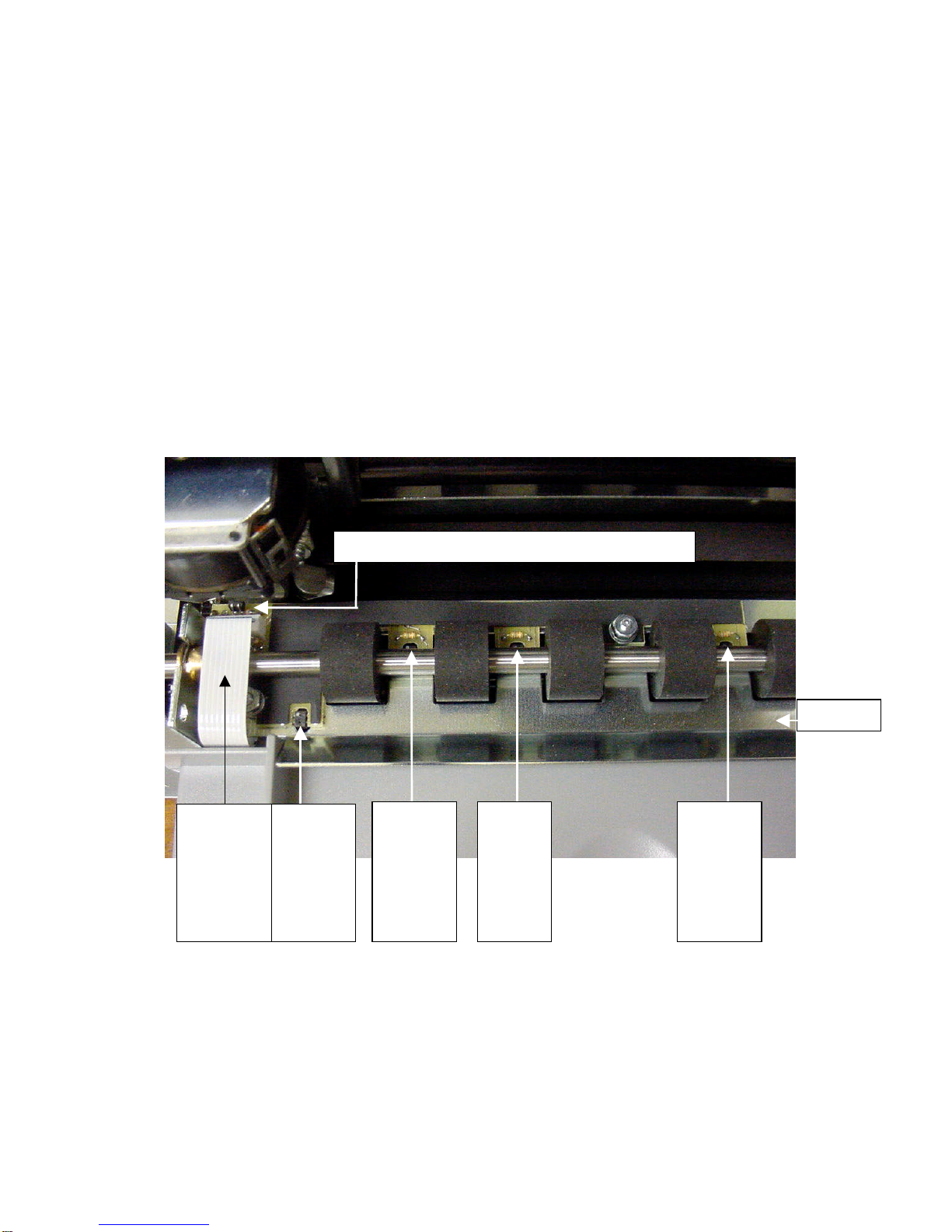
5.1.3 Sensor Cleaning
Clear sensor light paths of paper, paper dust and other obstructions if rollers continue to run
when no document is present or other sensor problems occur.
1. Insert the flexible nozzle tube of a compressed air can under the input guide and near each
of the document sensors. Clear each sensor area with a 5-second burst of air.
L- Left (Home) Sensor – synchronizes carriage motion
MultiSensor
Cable
Must be
seated in
connector
properly
F-
Front
Sensor
Senses
document
insertion
B-
Back
Sensor
Senses
document
top edge
M-
Middle
Sensor
Detects
skew
R-
Right
Sensor
Detects
skew
Input Guide
27
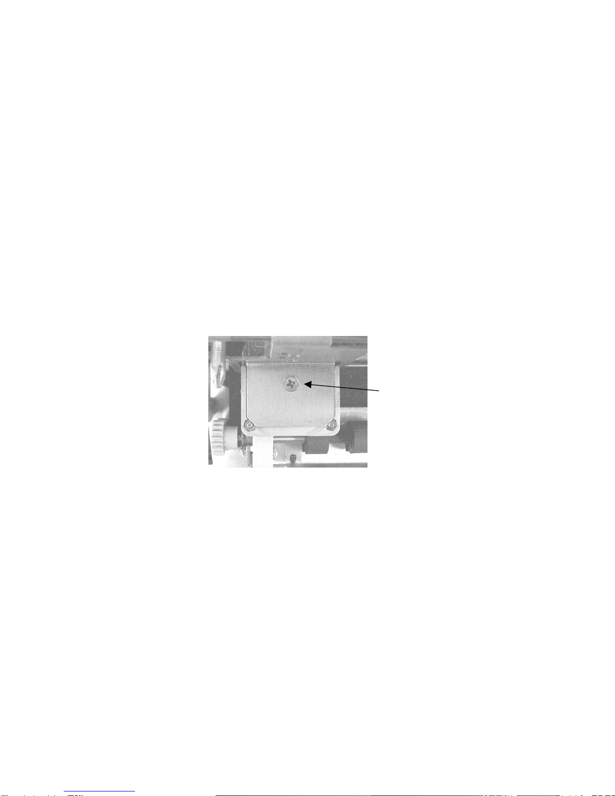
5.1.4 Printhead Cleaning
Perform if printwires stick when printing begins or print quality becomes intermittent. Be sure
to check the ribbon first! The 73297-8 Printer Cleaning Kit contains all necessary tools.
1. Open the cabinet and remove the ribbon cartridge.
2. Remove the printhead attachment screw.
3. Disconnect the printhead from the printhead flex cables.
4. Clean the tip of the printhead nose where the printwires extend from the printhead with an
alcohol wetted napkin. Remove all ink and bits of ribbon fabric lint.
5. Use the blunt end of a printhead cleaning brush to remove the bulk of the grease packed
around the printwires. Then wet the brush end with alcohol to remove the rest of the grease
from the printwires. Wipe the grease, ink and ribbon fabric “lint” from the brush onto the
napkin provided. Remove all residual alcohol
6. Reconnect the printhead to the flex cables and remount the printhead. Insure that the flex
cables don’t touch the carriage belt drive pulley or idler pulley bracket when the carriage
approaches the left and right box flanges.
7. Reinstall the ribbon cartridge. Perform a test print.
5.1.5 Document Print Area Cleaning
Accumulated paper dust should occasionally be removed from the platen, printhead, carriage
shaft, feed rollers, document sensors and other document path areas with brush, vacuum or
compressed air.
5.1.6 Cabinet Exterior Cleaning
The cabinet can be cleaned with a damp cloth and a mild, liquid soap or detergent. Do not
use harsh, abrasive cleaners.
DP8/9 carriage top view
Printhead attachment screw
28

5.2 SERVICE PARAMETER SET-UP PROCEDURE
It may be necessary to change service parameters that compensate for certain mechanical
tolerances. These parameters are listed on a label inside the printer and may be changed if
necessary by 94 FUNCT(see 3.5.4). If mechanical parts are replaced some parameters may
have to be reset. New parameter values should be marked on the configuration label.
The service parameters are determined by using 95 FUNCT local print and either 955 and 944
FUNCT or just 943 FUNCT as described below. Parameter values are changed with the A
and Bkeys. After changing a parameter, use 95, and either 955 and 944 or just 943, to
obtain new print samples. Re-measure all distances and re-adjust if necessary.
TOP OFFSET is set so the distance from the top document edge to the center of the first line
printed by 95 FUNCT is located as specified by LINE #1 = .XXX (.250 is the default factory
setting) under 92 FUNCT.
LEFT OFFSET is set so the carriage can still move leftward from its home position 0.01" to
0.02" (0.3 to 0.5mm) before it contacts the gate arm that raises the alignment gate.
LEFT MARGIN is set so the distance from the left document edge to the left edge of the first
character printed by 95 FUNCT is 0.20" (5.1mm) if edge sensing is not installed (EDGE
SENSOR parameter will not appear below).
CAR ALIGN is set so either the vertical strokes of H’s printed by 955 FUNCT (firmware E9 and
earlier) from right to left align with those printed left to right or the zeros printed by 943 FUNCT
(firmware EA and later) align. See 5.4.2 for precise adjustment but do not change the belt
tension unless necessary.
FORWARD and REVERSE COMPENSATION are set using either 943 or 944 FUNCT:
a. Procedure for firmware E9 and earlier (see 3.7)
944 FUNCT prints lines of overlapping X's and O’s 10" apart.
Set FORWARD COMPENSATION so that the distance between lines of X's is 10.00"
(254mm) +/- 0.02” (0.5mm)
Set REVERSE COMPENSATION so that the line of O's printed at the top of the page
overlaps the line of X's within 0.02” (0.5mm).
b. Procedure for firmware EA and later (see 3.7)
943 FUNCT prints line pairs with values of –4 through +4.
Set both FORWARD and REVERSE COMPENSATION with the value whose line pair is
closest to 10.00" (254mm) +/- 0.02” (0.5mm)
EJECT HOLD OFFSET is set so that an ejected document is still held in the drive rollers but
can be removed by pulling gently on it.
CONFIGURATION selects certain custom operating features and should not be set to a value
other than shown on the configuration label without contacting the factory.
GATE OFFSET is set by the Auto Alignment Gate Height procedure (see 5.4.7)
EDGE SENSOR is set so the distance from the left document edge to the left edge of the first
character printed by 95 FUNCT is 0.20" (5.1mm). This parameter is available on DP8 serial
number 182057 and higher and DP9 serial number 293501 and higher.
NORMAL DARKNESS Lower values reduce darkness and increase ribbon life at normal print
speed. Select the lowest value that provides suitable legibility on thick forms.
CQ DARKNESS similarly controls darkness at correspondence quality print speed.
PRINTHEAD TYPE (early DP8 only) adjusts print pulse timing for two different printheads that
have different drive characteristics. Select AUTO DETECT unless serial number is below
81000. Then select BLACK or SILVER printhead body color. A BLACK head can be damaged
if set to SILVER.
5.3 ELECTRICAL ADJUSTMENTS
There are no electrical adjustments required.
29

5.4 MECHANICAL ADJUSTMENTS
5.4.1 Printhead Gap
Too large a gap causes light print and missing dots. Too small a gap causes ribbon smear.
1. Open the cabinet, raise the carriage with the lift ring and remove the ribbon cartridge.
2. Hold the ribbon shield at its corners between the shield face and shield base. Raise the
ribbon guide plate and push the shield down and slide it to the right side to remove it.
3. Lower the carriage. Insert a narrow .015" (.38 mm) feeler gauge between the platen
(printing surface) and printhead nose from the side of the printhead. Insure that the feeler is
flat against the platen and completely under the printwires (not under the gap wheel or
behind the printwires). The .015" feeler should just fit without raising the printhead but a
slight resistance should be felt as the feeler slides below the printwires.
4. If the gap is incorrect, slightly loosen the two larger head screws on either side of the
printhead that fasten the gap plate to the printhead. (Use a 5/16” wrench to hold the
mounting nuts). The gap changes as these screws are loosened so only loosen them
enough to be able to move the plate.
5. Decrease the gap by pushing the printhead down against the feeler. Increase the gap by
rotating a screwdriver blade in the slot between the gap plate and the printhead Insure that
the gap plate is centered around the printhead nose and tighten the screws. Recheck the
gap per step 4.
6. Replace the ribbon shield by raising the carriage, sliding the shield from the side between
the carriage and the ribbon guide plate until the shield slot is centered. Gently push the
shield up until it snaps into place.
7. Mount the ribbon and use 95 FUNCT to print (See 3.8) and check print quality. Adjust the
NORMAL and CQ DARKNESS parameters (see 5.2).
Insert the feeler gauge from the side of the printhead. Be sure
the feeler gauge passes under the printwires only. (Front roller
and input guide removed for clarity)
30

5.4.1.1 Ribbon Shield Removal / Replacement
The ribbon shield prevents ribbon fabric from rubbing on and smearing printed media. It is a
consumable. Replace the shield every four to five ribbon replacements or when it is damaged.
Open the cabinet, center the carriage and pull the
lifter ring out and down to raise the carriage. Remove
the ribbon cartridge.
Lifter
Ring
Carriage
Shaft
Lift the carriage shaft with one hand and
pull the shield down and out to the right
with the other.
Shield
Tips
Pull the ribbon guide plate tabs toward
you. Insert the new shield tips into the gap
between the ribbon guide plate and the
carriage
Ribbon
Guide Plate
Carriage
Tabs
Rotate the shield until it is centered on
the carriage. Do not let the shield tips
slip behind the carriage.
Push the shield up until it stops.
Install the ribbon cartridge and
lower the carriage. Move the carriage lifter ring up and in to lower
the carriage. Close the cabinet turn the printer
on and do a test print or transaction.
65
43
21
31
Other manuals for DP8
5
This manual suits for next models
1
Table of contents
Popular Printer Accessories manuals by other brands


Star Micronics
Star Micronics TSP800 Series install guide

Citizen
Citizen CBM-202PC Series user manual

Canon
Canon Color imageCLASS MF8170c installation instructions

Codonics
Codonics Virtua 1VCX-LR833 Technical brief

Roland
Roland DU2-64 Supplementary manual

TonerRefillKits
TonerRefillKits ReChargX RX126 instructions