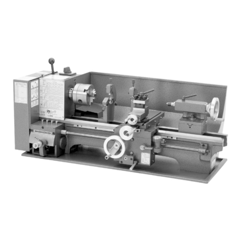
Craftex B1979C User manual

B1979C – MINI METAL LATHE, 7” X 8”
OWNER’S MANUAL

2
Table Of Contents
General Safety Instructions………………………………………………..…Page 4
Introduction………………………………………………………………….…Page 5
Package Contents………………………………………………………….…Page 6
Installation and Test Run………………………………………………...Page 7 - 9
Maintenance and Operation……………………………………………Page 10 -17
Replacement of Chuck………………………………………………Page 11
Replacement of Jaws & Compound Rest Adjustment…………..Page 12
Tailstock Adjustment & Replacement of brushes………………..Page 13
Tool Post Adjustment……………………………………………….Page 14
Automatic Feeding……………………………………………….….Page 15
Threading……………………………………………….……………Page 16
Operation of Cutting……………………………………………...…Page 17
Parts Listing…………………………………………………………....Page 18 – 20
Schematic Diagram…………………………………………………………Page 21
Warranty……………………………………………………………………...Page 22

3
EXTREME CAUTION SHOULD BE USED IN OPERATING ALL POWER TOOLS. KNOW
YOUR POWER TOOL, BE FAMILIAR WITH ITS OPERATION. READ THE OWNER’S
MANUAL AND PRACTICE SAFE USAGE PROCEDURES AT ALL TIMES.
GENERAL SAFETY INSTRUCTIONS
CONNECT your machine ONLY to the matched and specified power source.
WEAR SAFETY GLASSES, RESPIRATORS, HEARING PROTECTION
and SAFETY SHOES when operating this machine.
DO NOT wear loose clothing or jewellery when operating machinery.
A Safe Environment is important. Keep the area free of dust, dirt and other
debris in the immediate vicinity of the machine.
BE ALERT! Do Not Use prescription or other drugs that may affect your ability
or judgement to safely use this machine.
DISCONNECT the power source when changing tool bits
NEVER leave an operating tool unattended.
NEVER reach over the tool when it is in operation.
ALWAYS keep blades, knives or bits sharp and properly aligned.
ALWAYS keep all safety guards in place and ensure their proper function.
ALWAYS make sure that any tools used for adjustments are removed before
operating the machine.
ALWAYS secure your work with the appropriate clamps or vises.
ALWAYS keep bystanders safely away while operating machinery.
THINK SAFETY. WORK SAFELY. Never attempt a procedure if it does not
feel safe or comfortable.

4
Introduction
As part of the growing line of Craftex woodworking equipment, we are proud to
offer the B1979C Mini Metal Lathe. The Craftex name guarantees Craft
Excellence. By following the instructions and procedures laid out in this owner’s
manual, you will receive years of excellent service and satisfaction. The B1979C
is a professional tool and like all power tools, proper care and safety procedures
should be adhered to.
B1979C Mini Metal Lathe is a very practical machine which has been constructed
in a simple and logical way. This machine is perfect for the home workshop,
school workshops and for the instrument industry.
Installation and operation of the B1979C is very simple.
By changing gears, B1979C can cut metric threads.
The main spindle is powered by a 1/3 HP (250 W) permanent magnet DC motor
driven by a synchronous toothed belt. The variable speed mechanism allows free
adjustment of speed to achieve specific results of the work at hand.
The Lathe has 2 gears, a top (high) gear and a bottom (low) gear. The range of
speed with the high gear is 460 – 2500 RPM, while the low gear ranges from 200
– 1150 RPM, thus making this little machine quite the versatile tool.
Precision cast iron construction
Features
Auto longitudinal feed
Collars calibrated in inches
The ideal tool for model engineers and metal working hobbyists
Complete with precision 3-jaw chuck, change gear set, wrenches and allen keys
Swing Over Bed: 7”
Specifications
Swing Over Cross Slide: 4 ½”
Distance between Spindles: 8 ¼”
Spindle Taper: MT3
Bore: 13/16”
Spindle Speed Range: 200-2500 RPM
Threading Range: Inch – 12-48 TPI, Metric – 0.4-2.0 mm
Tailstock Taper: MT2
Tailstock spindle travel: 1 7/8”
Motor: 1/3 HP, 110V, Variable Speed
Size of Machine: 28” x 11 3/8” x 11 ¼”
Approx. Shipping Weight: 47 kg
Carton Size: 12” x 13 ½” x 27”
5
B1979C – PACKING LIST

6
Installation and Test Run
When unpacking the case, that your machine B1979C has arrived in,
try and follow the following instructions.
1) Remove the top board and the tip-boards first, and then twist the 4 bolts off
the bottom. Look into the accessory bag where you will find 4 rubber feet for
the lathe. Fix these rubber feet to the lathe with size 6 x 20 bolts (see diagram
below).

7
2) Set the machine onto a solid table, or bench top (ideally where you will be
using the machine) and make sure that the 4 rubber feet/cushions are firm
and secure, holding your B1979C in place.
3) You will find that the machine is packed with a grease-protecting agent to aid
and prevent damage/rust during shipping. Clean the surfaces of the machine
(non-painted parts) with varsol to wipe the away the anti-rust agents. When
complete make sure the machine is clean and dry.
4) With the purchase of any machine, you want to double-check all the
components of the machine to make sure that everything is intact. Go ahead
and do this now, also making yourself familiar with your new mini metal lathe.
5) Your B1979C is now ready to be turned ON. Before doing so, please be sure
that the power switch, direction switch and the speed control adjustment are
in the “OFF” position. Note: You will hear a click when the speed control is in
the OFF position.
6) Plug in the machine to the appropriate 110V outlet, and turn the power switch
to ON. Toggle the direction switch to your desired rotation (towards you or
away from you), and then press the “START” button. The machine is now
ready to run. Turn the speed dial to the ON position (just after the click). For
the initial run, let the machine run at the slowest speed for no less than 2
minutes to ensure the machine is stable and running normally. After the initial
warm up period you can now operate your lathe normally.
7) Be sure to turn the machine off before changing the gear. “L” position is
low/bottom gear, and “H” position is high/top gear.
8) At any time during operation, if there is a power outage, or a blackout, turn
the speed control knob to the lowest position. When electricity resumes, press
the start switch and your lathe will continue to provide you with excellent
service.

8
This machine has an overload protective switch, which limits the depth of feed.
When the main spindle is turning at 1000r/min in the bottom gear, the depth of
the feed must be within 4mm (0.16”) For the spindle turning at 1000r/min in top
gear, the depth of the feed must be within 2mm (0.079”). If the depth of feed is
beyond the limits mentioned above, then the overload protection device will cut
off the electrical supply. To ensure your safety, please be sure to follow the
guidelines and procedures laid out in this manual.
Additional Remarks

9
Maintenance and Operation
Your Craftex B1979C Mini Metal Lathe will provide you with years of excellent
service and satisfaction. Like any other machine, maintenance is very important
to the life of your lathe. There are a few certain things that one should do as
regular as possible in order to keep the lathe in top condition. The following are
easy and fast methods to maintaining you B1979C.
1) Everyday, or before starting, lightly coat the bed way, saddle way, feeding
screw, lead screw and gears with #10 engine oil. The more that this is done
the better.
2) After use, clean out the broken chips and workpieces and any grease or dirt
on the bed way. Wipe the parts of the machine down and smear the bed way
with oil again.
3) After heavy/long usage of your B1979C, apply a high lubricating grease to
maintain the spindle bearing.
1 – Gear Box
2 – Power Switch
3 – Main Spindle Box
4 – Speed Control Knob
5 – Main Spindle
6 – Traverse Feeding Hand Wheel
7 – Tool Fixing Handle
8 – Slide Plate Handle
9 – Tailstock Sleeve Fixing Handle
10 – Tailstock Sleeve Slide Hand
Wheel
11 – Tailstock Fixing Hand wheel
12 – Half Screw Adjusting Handle
13 – Apron Longitude Moving Hand
Wheel
14 – Changing Speed Fork Handle

10
Daily Maintenance
1) Inspect each operating part of the machine to ensure the condition of
lubrication
2) Examine each component to ensure that no parts have functional problems
3) Clean and remove any dirt, debris or obstacles in and around the machine in
order top prevent machine damage.
4) Lubricate all moving parts daily to prevent rust
Seasonal Maintenance
1) Use a cotton or soft gauze to clean each part of the machine
2) Confirm that the motion of the head and fixture are operating in a smooth and
correct manner
3) Check the spindle and swing of machine
4) Check the tightness of each nut and bolt
5) Examine the overall circuit (contact point connectors, plugs, switches …)
6) If there are any repairs or abnormal maintenance required at the time of your
check, please contact a licensed professional for aid.
Replacement of Chuck
When replacing the chuck, place a cloth or a piece of wood on the bed way at the
bottom of the chuck. This is to avoid any damage to the bedway caused by
carelessly dropping the chuck. Loosen the 3 set screws and replace the chuck.
(see Fig. 6 below)

11
Replacement of jaws
The jaws are in two types – the internal jaws and the external jaws. Please pay
notice that the number of jaws fit with the number inside the chucks groove. Do
not mix them together. When you are going to mount them, please mount them in
ascending order, and when taking them out, take them out in descending order
(3-2-1) one by one. After you finish this procedure, rotate the jaws to the smallest
diameter and make sure there fit is right.
Compound Rest Adjustment
Loosen the two screws as shown in the below figure. After you have obtained the
angle you want, do not forget to tighten them again. (see A in Figure 8)

12
Tailstock Rest Adjustment
When you are going to change the position or replace the tailstock you need to
loosen the nut.
Replacement of Carbon Brushes
Replace the carbon brushes by removing the brush covers both on the motor
cover and on the bottom right side of the speed control as shown in the figure
below (10A & 10B)

13
Tool Post Adjustment
When you are going to adjust the tool post position, you only need to loosen the
lever shown in the below figure (B). After you have finished, be sure to tighten. If
you are going to replace the work cutter, you need to loosen the screws show in
the diagram below (A)

14
Automatic Feeding
Adjust the feeding direction selector to the direction you desire. Then press down
the handle (A) as shown in the figure below and continue with the automatic
feeding procedure. When feeding, never try to change the feed direction.
Threading
Select the feeding direction selector to the thread direction you desire. Then
press down on the handle (A) in the figure below by matching the right
calibrations on the thread dial indicator and continue with the automatic threading
procedure. When threading, never try to change the direction.

15
Operation
Use the chuck to hold the workpeice firmly. Then use the rolling center to fix the
other end. If you change the rolling center to the drilling chuck you can start your
drilling immediately. See figure below.
Use the chuck to hold the work-piece firmly and the cutter to start the lathes face
cutting as show in the figure below. The edge of the cutter must be at the same
height as the center.

16
By changing the tool post angle and adjusting the compound rest, you can do
internal cutting as shown in the figure below.
After adjusting the angle of the compound rest, you can perform bevel cutting as
shown below.

17
B1979C – PARTS LISTING

18

19

20
Table of contents
Other Craftex Lathe manuals

Craftex
Craftex CX801 User manual

Craftex
Craftex CT039 User manual

Craftex
Craftex CX800 User manual

Craftex
Craftex CX706 User manual

Craftex
Craftex CX series User manual

Craftex
Craftex CT172 User manual

Craftex
Craftex CX series User manual

Craftex
Craftex CX708 User manual

Craftex
Craftex CX704 User manual

Craftex
Craftex CX series User manual