CRAIG & DERRICOTT SMART ION CHARGE EV03221000 Maintenance and service guide
Contact Us
Craig & Derrico Ltd | 46 Hall Lane I Walsall Wood I Walsall I West Midlands I WS9 9DP I United Kingdom
+44(0) 1543 375 541 | sales@craigandderrico.com | www.craigandderrico.com
INSTALLATION & MAINTENANCE
FOR SMART ION CHARGE ELECTRIC VEHICLE CHARGER
MODELS NUMBERS - EV03221000 & EV03221010
PLEASE READ IN FULL BEFORE INSTALLING ANY PRODUCTS

EVC0047 – Issue 1 2 | Page
IMPORTANT SAFETY INFORMATION
NOTES .......................................................................................................................................................................3
WARNINGS................................................................................................................................................................3
CAUTIONS .................................................................................................................................................................3
PRODUCT OVERVIEW
PRODUCT SPECIFICATION – ION EV CHARGER ..........................................................................................................4
PRODUCT SPECIFICATION – IONSENS........................................................................................................................4
ABOUT SMART ION
SUMMARY.................................................................................................................................................................5
ION EV CHARGER COMPONENTS – SOCKETED VERSION...........................................................................................7
ION EV CHARGER COMPONENTS – TETHERED VERSION...........................................................................................8
EV CHARGER KITS......................................................................................................................................................9
EV CHARGER INSTALLATION
CHOOSING A LOCATION ..........................................................................................................................................10
CHOOSING A HEIGHT TO FIX THE CHARGER TO THE WALL.....................................................................................10
WALL BRACKET FIXING............................................................................................................................................10
INSTALL IONSENS ....................................................................................................................................................11
MAINS CABLE CONNECTION ...................................................................................................................................12
TETHERED CABLE CONNECTION..............................................................................................................................12
CABLE CONNECTION TO EV CHARGER ....................................................................................................................13
COVER FITTING........................................................................................................................................................13
EV APP INSTALLATION
ETHERNET SETUP....................................................................................................................................................14
WI-FI SETUP............................................................................................................................................................16
CHARGER SETUP.....................................................................................................................................................17
EV APP & CHARGER SETTINGS
CHARGER LED STATUS INDICATION .........................................................................................................................18
HOW TO USE THE KEY FOB WITH THE RFID ............................................................................................................18
MAINTENANCE
GENERAL MAINTENANCE........................................................................................................................................19
CLEANING................................................................................................................................................................19
TROUBLESHOOTING................................................................................................................................................19
WARRANTY..............................................................................................................................................................19
DISPOSAL.................................................................................................................................................................19
TABLE OF CONTENTS

EVC0047 – Issue 1 3 | Page
NOTES
Please read all instrucons before Installing and using this product. Store in a safe place for reference.
The EV charger should be installed, commissioned, and maintained by or under the supervision of a competent
electrician in accordance with current electrical engineering codes of pracce, requirements for electrical
installaons (BS7671), statutory requirements and any specic instrucon issued by the company.
Damage to the equipment, connected systems or to property caused by improper installaon are the responsibility
of the installer.
WARNINGS
Warning: Do not install or use the EV charger near ammable, explosive, harsh, or combusble materials, chemicals,
or vapours.
Warning: Turn o the power at the circuit breaker before installing.
Warning: The EV charger must be grounded through a permanent wiring system.
Warning: Use the EV charger only within the specied operang parameters.
Warning: Never spray water or any other liquid directly at the EV charger, or IONsens.
Warning: Never submerge the EV charger, Charge plug or IONsens in liquid.
Warning: Store the charge plug (EV03221010) in the dock staon to prevent unnecessary exposure to contaminaon
or moisture.
Warning: Do not use the EV charger plug if it is defecve, appears cracked, frayed, broken, or otherwise damaged.
Warning: The EV charger plug and IONsens is not user serviceable. Do not aempt to disassemble, repair, tamper
with, or modify. Contact Craig & Derrico to report any damage or faults.
Warning: Do not touch the EV charger plug terminals with ngers or sharp metallic objects, such as wire, tools, or
needles.
Warning: Do not insert ngers or foreign objects into any part of the EV charger socket.
Warning: Use of the EV charger may aect or impair the operaon of any medical or implantable electronic devices,
such as a cardiac pacemaker or an implantable cardioverter debrillator. Check with your electronic device
manufacturer concerning the eects that charging may have on such electronic devices before using the EV charger.
CAUTIONS
Cauon: Do not use private power generators as a power source for charging.
Cauon: Incorrect installaon and tesng of the EV charger could potenally damage the vehicle's baery,
components, and/or the EV charger itself.
Cauon: Do not operate the EV charger or IONsens in temperatures outside its operang range -30°C to +50°C.
Cauon: Do not use any adaptors or cable extension cords with this EV Charge unit.
IMPORTANT SAFETY INFORMATION

EVC0047 – Issue 1 4 | Page
This OCCP compliant EV charger is an easy to install unit for residenal locaons. It oers 7.4kW single phase fast
charging. Plug and charge via the ION charge App or RFID operaon.
This EV charger is equipped with PME fault detecon with no requirement for an earth rod. The unit also supports
dynamic load balancing / management and solar charging via the IONsens device, that is included with your EV
charger.
PRODUCT SPECIFICATION – ION EV CHARGER
Power supply input
Nominal 230V AC single-phase
AC output current
32A
Mode 3 Fast Charge
7.4kW
Mains Cable Terminals
10mm2
Car Cable Charger Connecon
UK type 2
Frequency
50/60 Hz
Tethered Cable Length
5 metres
Independent back plate
For easy wall installaon
Product Size (mm)
351.5 x 280.5 x 140
Weight
3.1Kg (Socketed) - 5.2Kg (Tethered)
Operang Temperature (Indoor or outdoor)
-30°c to +50°c
Storage Temperature
-40°c to +85°c
Enclosure IP Rang
IP55
Connecvity
Integrated RFID reader for oine stop / start charging.
2.4Ghz WiFi, Bluetooth V4.2 and Ethernet connecvity.
Smart App for communicaon
Security
An- tamper device ed to main cover with alert
nocaon
Electrical Safety
Built in overcurrent and 6mA DC residual current
detecon. Instrucon: A type A RCD/RCBO must be
ed and placed upstream of the EV charger.
PME fault detecon (no earth rod required)
PRODUCT SPECIFICATION – IONSENS (inclusive of Current Transformer) for dynamic load balancing
IONsens Product Size (mm)
116 x 63 x 28 (not including CT)
Weight
20g (IONsens),
Operang Temperature (Indoor or outdoor)
-30°c to +50°c
Storage Temperature
-40°c to +85°c
PRODUCT OVERVIEW

EVC0047 – Issue 1 5 | Page
SUMMARY
The United Kingdom introduced regulaons that applies to domesc and private EV charge points. The regulaons
are designed to balance demands for power and to deliver an ecient use of power across the country whilst
maintaining a consistent and secure service to EV drivers.
Summary of smart capabilies (correct at me of print).
•Connected to a charging applicaon that can control your EV charger.
•Has the ability to receive remote, online soware updates.
•Capable of measuring the power used and the power delivered, and the associated me periods.
•Capable of storing and displaying data about charge sessions.
•Capable of communicaon with the power supplier and able to adjust the delivery of power in response to
commands issued by the supplier (This requires soware integraon with chosen supplier. Please contact
Craig & Derrico for more informaon).
•Capable of charging even in the event of communicaons with the network being lost.
•Data recorded about the charge session will be communicated at the next available opportunity when online.
•The ability to receive power from any electricity supplier. Incorporates o-peak charging as the default with
the ability to override if required.
•Randomised delay between iniang a charge session and the charge session starng. This is to prevent
overloads of the electricity system if many charge points are acvated the moment the o-peak period starts.
•Physical and digital protecon of data and of the components used to access that data.
•Physical protecon of electrical components within the charge point to prevent personal harm and to prevent
accidental or malicious tampering.
•Regulaons are connuously under review which may bring addional requirements in the future.
Load Balancing / Management device explained.
Load Balancing capability is designed to prevent overloads of the property’s power supply when a vehicle is being
charged.
The system will monitor the power being drawn by the charging process and will compare this to the permissible
maximum for the property (which is set as part of the conguraon).
With this informaon, the power made available for charging can be dynamically adjusted to reduce the load before
the property’s maximum load is exceeded.
For example, if the property’s main fuse (or circuit breaker) is rated at 60 Amps, the fuse will operate and cut all
power to the property if a draw of 60 Amps is exceeded. It can be relavely easy to draw signicant power if several
property appliances are in use at the same me.
Household appliance
Current load
Kettle
13A
Oven
13A
Dishwasher
10A
Iron
13A
Total current
49A
In this example, only 11 Amperes remain before the 60A limit is reached.
ABOUT SMART ION

EVC0047 – Issue 1 6 | Page
If an electric vehicle is now put on charge and drawing 16A, the limit would be exceeded, and the property’s fuse
would operate to cut all electrical power to the property.
With load balancing enabled, the amount of power made available for charging will be automacally adjusted to a
level that does not exceed the maximum for the property.
IONsens will connue to monitor the power and will dynamically increase and decrease the power made available
for charging in response to the demand for power from the rest of the property.
ION charge points are pre-congured to load balance with a 13A ‘buer’.
This means that whatever the property fuse may be load balancing will start 13A before its maximum limit is reached.
For example: If the charger is congured by the installer for use with a property with a 60A fuse, load balancing will
start at 47A. Similarly, for a property with an 80A fuse, load balancing will start at 67A. This allows combined use of
the charger plus other appliances in normal use with no eect on the property’s electricity.
In addion to the load balancing there is a built-in safety feature (Load management) that regulates and reduces the
charging current when the ambient temperature increases thus protecng the unit.
TruePEN PME fault detecon device explained.
This device removes the need to install a dedicated earth for the charge point.
In the event of a fault, the system will break all power cable connecons between the charge point and the vehicle.
A PEN fault is most seen as either, an undervoltage or an overvoltage entering the charge point from the mains supply.
Following inial power ON, the system monitors the supply voltage for 5 seconds and determines if the voltage is
within normal operang parameters. If within limits, the system allows the connecon of Live, Neutral and Earth to
the vehicle and connues to monitor the supply.
If the voltage goes out of limits (below 207 Volts or above 253 Volts) for a connuous period of 5 seconds, this could
be caused by a PEN fault. The TruePEN device will acvate (‘trip’) and isolate Live, Neutral and Earth to the vehicle.
Undervoltage: Following an undervoltage trip, TruePEN connues to monitor the supply and if the voltage returns to
within limits for a connuous period of 5 seconds, the TruePEN device will automacally reset and restore the Live,
Neutral and Earth connecons to the vehicle, allowing charging to resume.
Overvoltage: An overvoltage condion is potenally more likely to damage the vehicle so, for safety reasons,
automac recovery following an overvoltage is NOT provided and charging cannot resume unl a manual reset is
performed.
Following an overvoltage condion, EV drivers are advised to invesgate as far as they can, the reasons for the
overvoltage condion and to check their vehicle for correct operaon. Occasional overvoltage condions may simply
be caused by uctuaons in the supply but if they are frequent, the cause should be invesgated by an appropriately
qualied and experienced electrical engineer and/or the electricity supply company.
Security –Tamper Protecon device explained.
It is a requirement in the United Kingdom that charge points of this type, sold aer 30th December 2022, have two-
levels of an-tamper protecon.
•Charge points must incorporate a boundary to guard the electrical components from tampering whilst also
providing safety to electrical engineers. A tamper proof screw is ed to prevent inadvertent removal of the
front escutcheon cover. See Fig1 & 3, Item C
ABOUT SMART ION

EVC0047 – Issue 1 7 | Page
•Charge points must log and issue an alert to the customer / user if there is a breach of the boundary. The
purpose of this device is to protect people from harm, protect the charge point, the charging network, and
the electricity network from malicious or accidental damage or abuse and protect the data held on the charge
point.
•A pushbuon switch is ed beneath the front escutcheon cover, when the cover is removed the switch will
acvate and send an alert to the ION charge App nofying the customer / user.
•If the front escutcheon cover is not ed, then the EV charger will be inacve.
ION EV CHARGER EXTERNAL COMPONENTS – SOCKETED VERSION Fig.1
ION EV CHARGER INTERNAL COMPONENTS – SOCKETED VERSION Fig. 2
Supplied with:
•IONsens including CT
•2 x User Key Fob (Pre-paired)
ABOUT SMART ION
A
B
C
D
E
F
G
H

EVC0047 – Issue 1 8 | Page
ION EV CHARGER EXTERNAL COMPONENTS – TETHERED VERSION Fig. 3
ION EV CHARGER INTERNAL COMPONENTS – TETHERED VERSION Fig. 4
Supplied with:
•IONsens including CT
•2 x User Key Fob (Pre-paired)
•1 x 5m Type 2 EV Cable & Plug
ABOUT SMART ION
C
B
A
D
E
F
G
H

EVC0047 – Issue 1 9 | Page
EV CHARGER KITS Fig. 5
ABOUT SMART ION
1
2
4
5
6
7
9
10
8
3

EVC0047 – Issue 1 10 | Page
CHOOSING A LOCATION
Install the EV Charger in a locaon that allows the charging cable to reach the vehicle charge port without pung
strain on the cable. Tethered cable length is 5m, therefore, a recommended distance would be no greater than 3m
from the car charging point.
CHOOSING A HEIGHT TO FIX THE CHARGER TO THE WALL
Recommend the EV charger is 1.2metre from ground to centre of cable socket.
WALL BRACKET FIXING
Once you have established the correct height, Using the wall bracket, mark 4 posions on the wall with a suitable
tool. Drill 4 holes and x the bracket to the wall with suitable C/SK screws (not supplied).
Fix EV charger to wall bracket with the 4 o xing screws (M5 x 16) supplied. Access through LH & RH Terminal
Cover apertures.
EV CHARGER INSTALLATION

EVC0047 – Issue 1 11 | Page
INSTALL IONSENS
The EV charger is supplied with a Load sensing device with one CT clamp, this must be ed near to your house
incoming supply where the house protecve fuse and meter is located. See Fig 7, Item 1.
The CT Clamp is to be ed to the incoming cable (see Fig 7 item 2) and the Black and white cable must be ed to
the terminals CT1.1 and CT1.2 inside the IONsens enclosure. When using EV charger power and data cable combined
ensure the data cable is ed to the IONsens socket (see Fig 6 RJ12) or connect a separate data cable in the same
way. For addional monitoring please contact Craig & Derrico to purchase addional CT clamps.
The IONsens is supplied with fastening pads for ng to a suitable locaon inside the house supply box, please clean
the locaon prior to xing.
Fig. 6
Fig. 7
CT1.2
CT1.1
RJ12
CT
Clamp
EV CHARGER INSTALLATION
1
2
EVC0047 – Issue 1 12 | Page
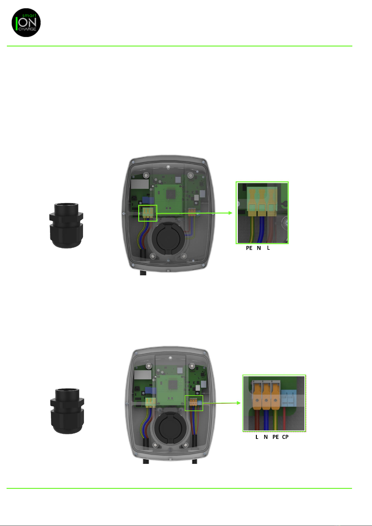
MAINS CABLE CONNECTION
The EV charger is supplied with a Mains M25 Nylon cable gland.
Note: For Steel wire armoured cable, a suitable gland will need to be used (not supplied).
Insert cable through LH entry cable gland and ghten glanding nut. Strip back cable and terminate cables into LH
terminal blocks.
Note: Care to be taken when terminang cables. Ensure conductors are terminated into their corresponding terminals
before energising.
TETHERED CABLE CONNECTION
If you have purchased the EV03221010 (Tethered EV Charger) the cable must be ed as follows:
1. Mains cable connecon, as per Step 3.
2. Insert cable through RH entry cable gland and ghten glanding nut.
3. Terminate cables into RH terminal blocks.
EV CHARGER INSTALLATION
1 x M25 Cable Gland:
2 x M25 Cable Gland:
EVC0047 – Issue 1 13 | Page
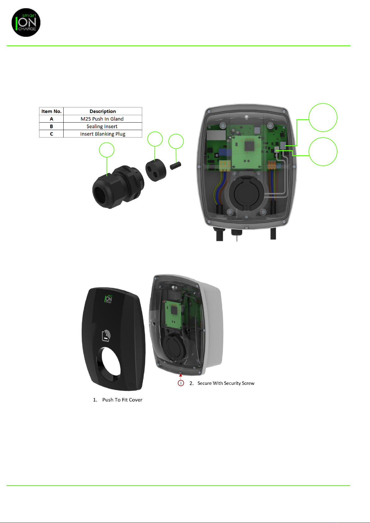
CABLE CONNECTION TO EV CHARGER FOR BOTH ETHERNET & IONSENS
1. Use push-in cable gland to allow ng of the IONsens and oponal ethernet cables.
2. The push-in cable gland is only required if the installaon power cable has no integrated data cable
included.
3. The ethernet cable is only required when the Wi-Fi signal is weak to your router.
COVER FITTING
Illustraon below for cover ng
EV CHARGER INSTALLATION
Ethernet
Cable
IONSens
Cable
C
B
A
EVC0047 – Issue 1 14 | Page
Your charger will require a connecon to the Internet. This can be done by either Ethernet or Wi-Fi.
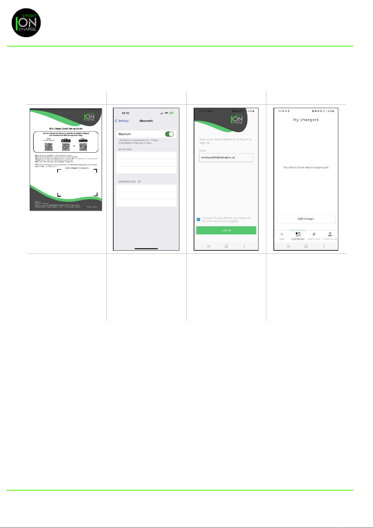
ETHERNET SETUP
Step 1
Step 2
Step 3
Step 4
Download the free Smart
ION Charge APP by
scanning the QR code on
the Quick Set-up Guide.
This will take you straight
to the correct App ready
to download.
Ensure your Bluetooth
settings are switched ON
within your device.
Enter a valid email address
to create your account. A
verification code will be
sent to this email address
to verify you as the user
and enable you to login.
Follow the on screen
instructions.
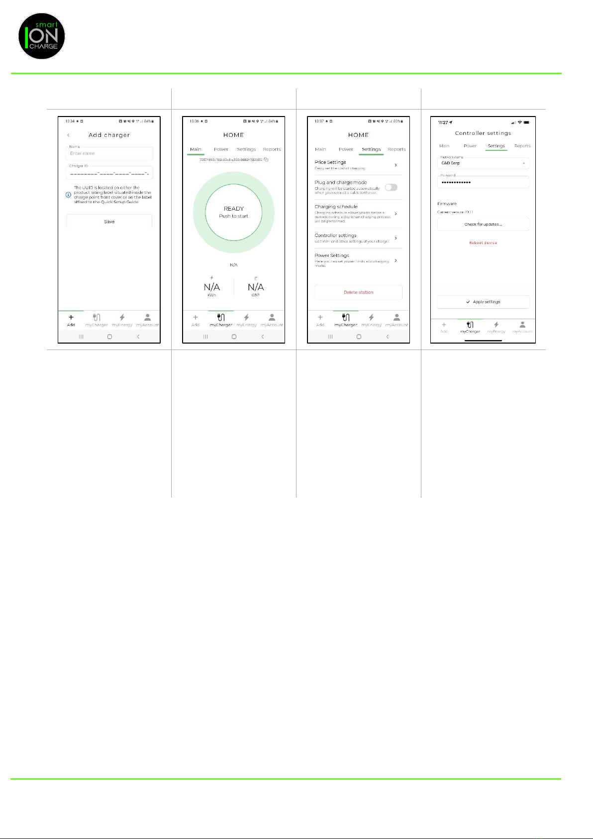
Step 1 Once logged in,
click on “Add Charger” at
the bottom of the screen.
EV APP INSTALLATION
EVC0047 – Issue 1 15 | Page
Step 5
Step 6
Step 7
Step 8
Name your charger and
locate the charger ID.
Scan the Charger ID QR
Code or enter the number
manually. (This can be
found on either the Quick
Set-up Guide or on the
cover of EV charger). Then
click “Save”. Security
Note: Please keep this
number secure.
The App will now take you
to the Charger home
screen and will display
“READY”.
Select “Settings” menu.
Then select “Controller
Settings”.
EV APP INSTALLATION
EVC0047 – Issue 1 16 | Page
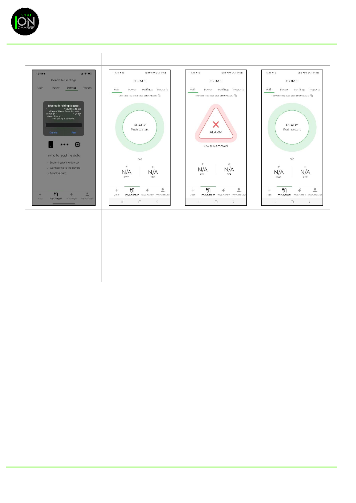
Step 9
Step 10
Step 11
Step 12
The App will then prompt
for Bluetooth Permission.
Enter the 6-digit BLE code
(This can be found on
either the Quick Set-up
Guide or on cover of EV
charger). Security Note:
Please keep this number
secure.
The App will now take you
to back to the Charger
home screen and will
display “READY”.
If the front cover has not
been fitted the App will
display Alarm or if the
cover is removed due to
unauthorised tampering
the same Alarm Alert will
be displayed.
Your setup is now
complete, and the charger
is ready to use.
WI-FI SETUP
Follow Step 1 to Step 5 on the Ethernet Setup
Step 6 The App will now take you to the Charger home screen and will display “OFFLINE”.
Step 7 Select “Sengs” Menu.
Step 8 Then select “Controller Sengs”.
Step 9 The App will then prompt for Bluetooth Permission. Enter the 6-digit BLE code (This can be found on
either the Quick Set-up Guide or on cover of EV charger). Security Note: Please keep this number
secure.
Step 10 Select your Wi-Fi network name from the dropdown menu.
Step 11 Enter your Wi-Fi password then select “Apply Sengs”.
Step 12 The App will now take you to back to the Charger home screen and will display “READY”.
Your setup is now complete, and the charger is ready to use.
EV APP INSTALLATION
EVC0047 – Issue 1 17 | Page
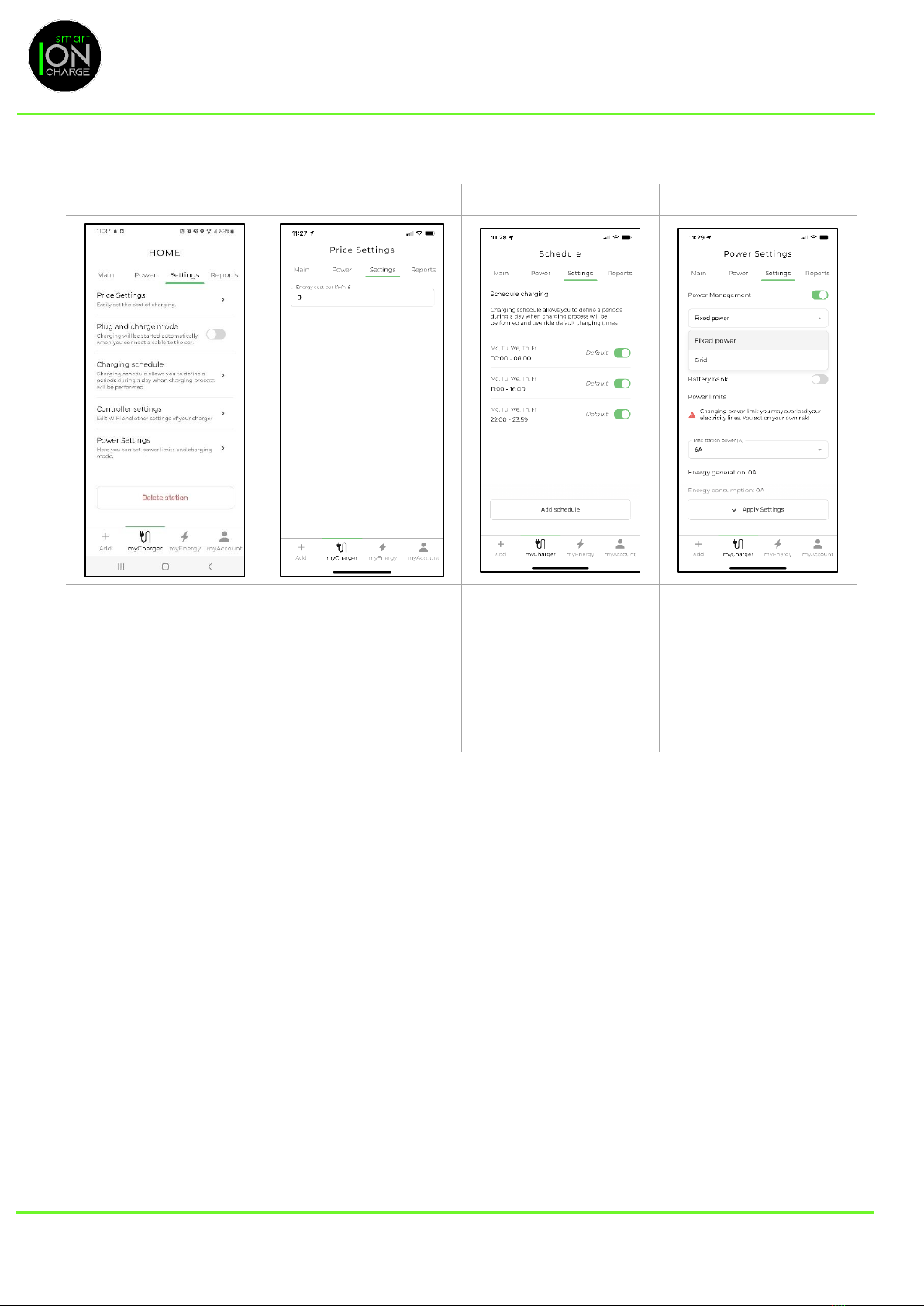
CHARGER SETUP GUIDE
Step 1
Step 2
Step 3
Step 4
Click on the setting tab
Click on Price settings and
enter your Energy cost per
kWh. If you click on the
“Reports tab” you will be
able to see your Energy
cost and Energy
consumed once your
charger has been in use.
Charging schedule default
charging time have been
set within the App but a
new schedules time can
be setup by clicking the
Add schedule button.
The Power Management
button will be ON when
IONsens is connected. The
drop-down menu allows
you to set the Max station
power. This can be set to
between 6A and 32A.
EV APP INSTALLATION

EVC0047 – Issue 1 18 | Page
CHARGER LED STATUS INDICATION
LED Colour
Indication
Green
Charger is online
Red
Charger is offline and an error has occurred
Blue
Car is charging
Violet
Car is charging in offline mode
Yellow
Offline, ready to charge (plug-in & charge)
Blinking Blue
RFID read / acknowledged
HOW TO USE THE KEY FOB WITH THE RFID
Note: 2 x User Key Fobs supplied pre-programmed.
When you swipe key fob over RFID symbol on front cover, this will inialise charging mode and the charger will use
the scheduled me to charge your vehicle, setup within your App.
If the EV charger is oine by swiping key fob over RFID symbol on front cover this will inialise charging mode
immediately.
EV APP & CHARGER SETTINGS

EVC0047 – Issue 1 19 | Page
GENERAL MAINTENANCE
Should the product be installed in a space that is accessible to the public, observe local and naonal requirements
(e.g., BS 7671) in addion to all other safety informaon contained within this manual.
CLEANING
Should the product require cleaning for cosmec purposes, use a damp cloth with an all-purpose household cleaner.
Avoid the use of strong chemical cleaners and cleaners that contain oil or alcohol, as this will tarnish the plasc.
Do not use running water or high-pressure water jets.
TROUBLESHOOTING
Please visit C&D website for latest EV charger trouble shoong ps or alternavely contact Craig & Derrico on 01543
375541. Please provide model and serial number.
WARRANTY
The EV Charger is covered for 36 months from proof of purchase.
Please visit our website www.craigandderrico.co.uk to register your purchase.
The warranty does not cover any damage or malfuncon directly, or indirectly caused by, or resulng from, misuse,
negligence, accident, or improper installaon.
DISPOSAL
This electronic equipment must not be disposed of in household waste. Observe local regulaons for correct
and environmentally friendly disposal.
MAINTENANCE
Other manuals for SMART ION CHARGE EV03221000
2
This manual suits for next models
1
Table of contents
Other CRAIG & DERRICOTT Automobile Batteries Charger manuals


