Crary CWS 1010 User manual

PN: 26037-00 R080307
Companion to 26038-00
Owner’s
manual
CASE IH
1010
1020
RECORD SERIAL NUMBER HERE

DISCLAIMER
This document is based on information available at the time of its publication. While efforts have been made to be accurate, the
information contained herein does not purport to cover all details or variations, nor to provide for every possible contingency in con-
nection with installation, operation, or maintenance. Features may be described herein which are not present in all systems. Crary
Industries assumes no obligation of notice to holders of this document with respect to changes subsequently made.
Crary Industries assumes no responsibility for the accuracy, completeness, sufficiency, or usefulness of the information contained
herein.
SPECIFICATIONS AND DESIGN ARE SUBJECT TO CHANGE WITHOUT NOTICE.
Crary Industries is continually making improvements and developing new equipment. In doing so, we reserve the right to make
changes or add improvements to our product without obligation for equipment previously sold.
Because modification to this machine may affect the performance, function, and safety of its operation, no modifications are to be
made without the written permission of Crary Industries. Part replacements should be with original equipment supplied by Crary
Industries.
THE CRARY INDUSTRIES STATEMENT OF PRODUCT SAFETY
As a manufacturer of specialized agricultural equipment, Crary Industries fully recognizes its responsibility of providing its customers
products that perform their expected use in a reasonably safe manner. Safety considerations shall be an integral and high prior-
ity part of all engineering/design analysis and judgments involving Crary products. It is our stated policy that our products will be
manufactured to comply with the safety standards specified by the American Society of Agricultural Engineers, the National Electrical
Code, the Society of Automotive Engineers, and/or any other applicable recognized standards at the time manufactured. However,
this statement should not be construed to mean that our product will safeguard against a customer’s own carelessness or neglect in
violating common safety practices specified in each product’s manual, nor will we be liable for any such act.
SERIAL NUMBER LOCATION
Always give your authorized Crary dealer the serial number of your
machine when ordering parts, requesting service, or any other in-
formation. The serial number decal is located on the front, left hand
end of the air manifold.
Please record the serial number in the space provided on the front
cover and on the warranty and registration card.
© 2007, Crary Industries, All rights reserved. Produced and printed in the USA.
HOw TO reaCH us
aDDress HOurs TelePHOne
FaX numBer
e-maIl
InTerneT
Crary Industries
237 12th St. NW
P.O. Box 849
West Fargo, ND 58078-0849
Mon. - Fri.
8 A.M to 5 P.M.
Central Time
For Parts and Service:
1-800-247-7335
Fax: 1-701-282-9522
For Service: serv@crary.com
Visit us on the web @
www.terramarc.com
Serial Number Decal
MANUFACTURED BY CRARY INDUSTRIES
MANUFACTURED IN U.S.A.
XXXXXX
WEST FARGO, NORTH DAKOTA 58078 U.S.A.
SERIAL NUMBER

PN 26037-00 R070607 1
LIMITED WARRANTY
This warranty applies to all AG and Outdoor Power Equipment manufactured by Crary Industries.
Crary Industries warrants to the original owner each new Crary Industries product to be free from defects
in material and workmanship, under normal use and service. The warranty shall extend 1 year from date of
delivery for income producing (commercial) applications and 2 years from date of delivery for non-income
producing (consumer) use of the product. The product is warranted to the original owner as evidenced by a
completed warranty registration on file at Crary Industries. Replacement parts are warranted for (90) days
from date of installation.
THE WARRANTY REGISTRATION MUST BE COMPLETED AND RETURNED TO CRARY INDUSTRIES
WITHIN 10 DAYS OF DELIVERY OF THE PRODUCT TO THE ORIGINAL OWNER OR THE WARRANTY
WILL BE VOID.
In the event of a failure, return the product, at your cost, along with proof of purchase to the selling Crary
Industries dealer. Crary Industries will, at its option, repair or replace any parts found to be defective in material
or workmanship. Warranty on any repairs will not extend beyond the product warranty. Repair or attempted
repair by anyone other than a Crary Industries dealer as well as subsequent failure or damage that may occur
as a result of that work will not be paid under this warranty. Crary Industries does not warrant replacement
components not manufactured or sold by Crary Industries.
This warranty applies only to parts or components that are defective in material or workmanship.
This warranty does not cover normal wear items including but not limited to bearings, belts, pulleys, filters
and chipper knives.
This warranty does not cover normal maintenance, service or adjustments.
This warranty does not cover depreciation or damage due to misuse, negligence, accident or improper
maintenance.
This warranty does not cover damage due to improper setup, installation or adjustment.
This warranty does not cover damage due to unauthorized modifications of the product.
Engines are warranted by the respective engine manufacturer and are not covered by this warranty.
Crary Industries is not liable for any property damage, personal injury or death resulting from the unauthorized
modification or alteration of a Crary product or from the owner’s failure to assemble, install, maintain or operate
the product in accordance with the provisions of the Owner’s manual.
Crary Industries is not liable for indirect, incidental or consequential damages or injuries including but not
limited to loss of crops, loss of profits, rental of substitute equipment or other commercial loss.
This warranty gives you specific legal rights. You may have other rights that may vary from area to area.
Crary Industries makes no warranties, representations or promises, expressed or implied as to the performance
of its products other than those set forth in this warranty. Neither the dealer nor any other person has any
authority to make any representations, warranties or promises on behalf of Crary Industries or to modify the
terms or limitations of this warranty in any way. Crary Industries, at its discretion, may periodically offer limited,
written enhancements to this warranty.
CRARY INDUSTRIES RESERVES THE RIGHT TO CHANGE THE DESIGN AND/OR SPECIFICATIONS
OF ITS PRODUCTS AT ANY TIME WITHOUT OBLIGATION TO PREVIOUS PURCHASERS OF ITS
PRODUCTS.
1.
2.
3.
4.
5.
6.
7.

PN 26037-00 R070607
2
CONTENTS
INTRODUCTION....................................................................................................... 4
SAFETY .................................................................................................................... 5
2.1 SAFETY ALERT SYMBOL ........................................................................................................................................................... 5
2.2 GENERAL SAFETY...................................................................................................................................................................... 6
2.3 OPERATING SAFETY.................................................................................................................................................................. 7
2.4 MAINTENANCE SAFETY ............................................................................................................................................................ 7
2.5 HYDRAULIC SAFETY.................................................................................................................................................................. 8
2.6 PTO SAFETY ............................................................................................................................................................................... 8
2.7 TRANSPORT SAFETY................................................................................................................................................................. 9
2.8 STORAGE SAFETY ..................................................................................................................................................................... 9
2.9 ASSEMBLY SAFETY.................................................................................................................................................................... 9
2.10 SAFETY DECALS ...................................................................................................................................................................... 9
2.11 SIGN-OFF FORM ..................................................................................................................................................................... 10
SAFETY DECALS....................................................................................................11
ASSEMBLY............................................................................................................. 12
4.1 REEL ARM MOUNT ................................................................................................................................................................... 12
4.1.1 LEFT HAND ...............................................................................................................................................................12
4.1.2 RIGHT HAND.............................................................................................................................................................13
4.2 MANIFOLD................................................................................................................................................................................. 14
4.3 AIR TUBES................................................................................................................................................................................. 15
4.4 HEADER PREPARATION .......................................................................................................................................................... 16
4.5 GEARBOX/FAN MOUNT - PRE 1993 SERIES.......................................................................................................................... 18
4.6 GEARBOX/FAN MOUNT - 1993/1994 SERIES (W/OUT GEARBOX STUB SHAFT)................................................................ 20
4.7 GEARBOX/FAN MOUNT - 1995 AND LATER SERIES (W/OUT GEARBOX STUB SHAFT).................................................... 22
4.8 GEARBOX/FAN MOUNT - 1993 AND LATER SERIES (W/ GEARBOX STUB SHAFT) ........................................................... 24
4.9 RIGHT HAND DRIVE KIT - PRE 1993 SERIES......................................................................................................................... 26
4.10 RIGHT HAND DRIVE KIT - 1993/1994 SERIES (15 FT - 22.5 FT).......................................................................................... 28
4.11 RIGHT HAND DRIVE KIT - 1995 AND LATER SERIES (15 FT - 22.5 FT) .............................................................................. 30
4.12 RIGHT HAND DRIVE KIT - 1993 AND LATER SERIES (25 FT - 30 FT W/OUT GEARBOX STUB SHAFT) .......................... 32
4.13 RIGHT HAND DRIVE KIT - 1993 AND LATER SERIES (25 FT - 30 FT W/ GEARBOX STUB SHAFT).................................. 34
4.14 ELECTRICAL WIRING ............................................................................................................................................................. 36
4.15 FLEX HOSE ............................................................................................................................................................................. 37
4.16 GEARBOX / FAN EXTENSION ................................................................................................................................................ 38

PN 26037-00 R070607 3
OPERATION ........................................................................................................... 40
5.1 MACHINE COMPONENTS ........................................................................................................................................................ 41
5.2 PRE-OPERATION CHECKLIST................................................................................................................................................. 42
5.3 MACHINE BREAK-IN ................................................................................................................................................................. 42
5.4 NEUTRAL DRIVE SHAFT (OPTIONAL)..................................................................................................................................... 42
5.5 CONTROLS................................................................................................................................................................................ 43
5.6 INITIAL ADJUSTMENTS ............................................................................................................................................................ 43
5.6.1 INITIAL ADJUSTMENT ..............................................................................................................................................44
5.6.2 TORQUE LIMITER.....................................................................................................................................................44
5.7 OPERATING HINTS................................................................................................................................................................... 45
5.8 TRANSPORTING ....................................................................................................................................................................... 45
5.9 STORAGE .................................................................................................................................................................................. 46
SERVICE & MAINTENANCE.................................................................................. 47
6.1 MAINTENANCE CHECKLIST .................................................................................................................................................... 47
6.2 FLUIDS AND LUBRICANTS....................................................................................................................................................... 48
6.3 GREASING................................................................................................................................................................................. 48
6.4 GEARBOX OIL ........................................................................................................................................................................... 49
6.5 PTO LUBRICATION ................................................................................................................................................................... 50
6.6 AUGER DRIVE CHAIN LUBRICATION ..................................................................................................................................... 50
6.7 AUGER DRIVE CHAIN TENSION AND ALIGNMENT ............................................................................................................... 51
6.8 FAN HOUSING AND AIR HOSE ................................................................................................................................................ 52
6.9 TORQUE LIMITER (SLIP CLUTCH) - DRIVELINE .................................................................................................................... 52
6.9.1 RUN-IN.......................................................................................................................................................................52
6.9.2 MAINTENANCE.........................................................................................................................................................52
6.10 TORQUE LIMITER (SLIP CLUTCH) - AUGER DRIVELINE..................................................................................................... 53
6.10.1 RUN-IN AND TORQUE ADJUSTMENT...................................................................................................................53
6.10.2 MAINTENANCE.......................................................................................................................................................53
TROUBLESHOOTING............................................................................................ 54
SPECIFICATIONS................................................................................................... 55
8.1 FAN PERFORMANCE DATA...................................................................................................................................................... 55
8.2 HYDRAULIC FITTING TORQUE ............................................................................................................................................... 56
8.3 BOLT TORQUE .......................................................................................................................................................................... 57
CONTENTS
PN 26037-00 R070607
4
Section INTRODUCTION
1
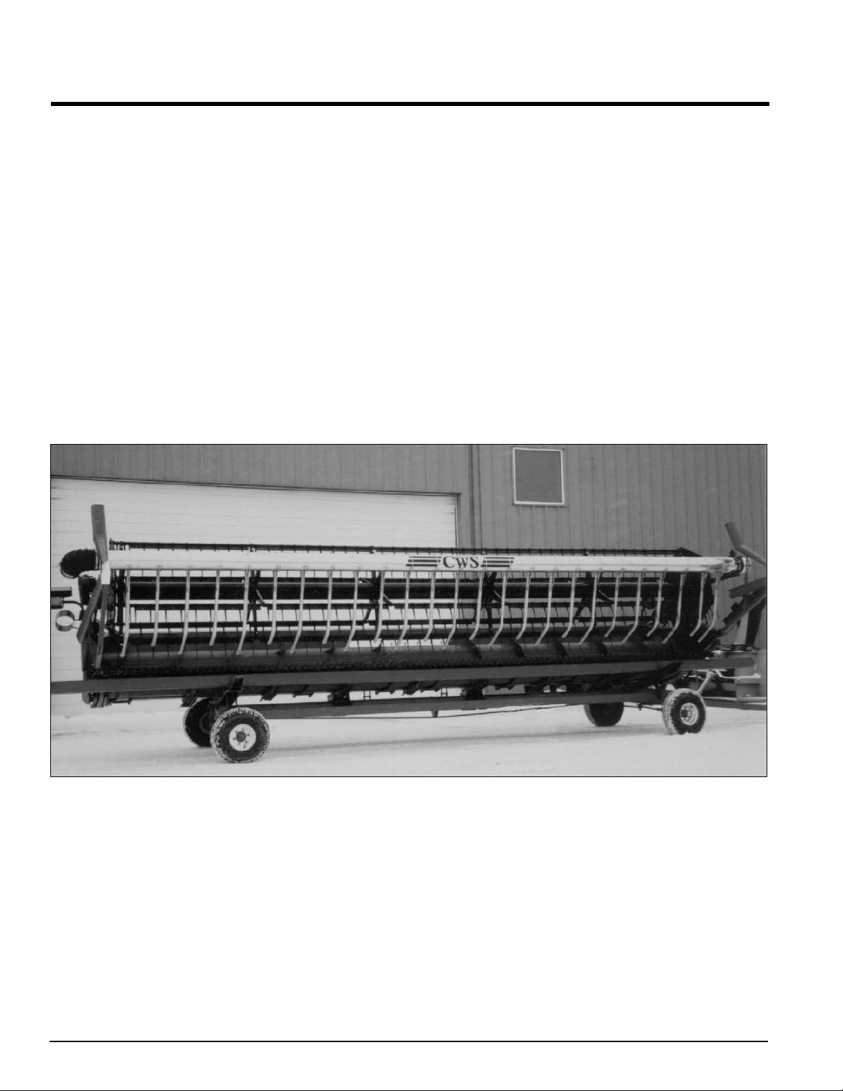
Congratulations on your choice of a new CWS to complement your farming operation. This equipment has been designed and manu-
factured to meet the needs of a discerning agricultural industry for the efficient harvesting of crops.
Safe, efficient, and trouble free operation of your CWS requires that you and anyone else who will be operating or maintaining the
machine, read and understand the Safety, Operation, Maintenance, and Trouble Shooting information contained within the Operator’s
Manual. Check each item referred to and acquaint yourself with the adjustments required to obtain efficient operation.
This manual covers all the CWS models manufactured by Crary Industries for Case IH headers. Use the table of contents as a guide
to locate required information.
Keep this manual handy for frequent reference and to pass on to new operators or owners. Call your Crary dealer or distributor if you
need assistance, information, or additional copies of the manuals.
Many people have worked on the design, production, and delivery of this machine. They have built into it the highest quality of ma-
terials and workmanship. The information in this manual is based on the knowledge, study, and experience of these people through
years of manufacturing specialized farming machinery.
The performance of the machine depends on proper maintenance and adjustment. Even if you are an experienced operator of this
or similar equipment, we ask you to read the operator’s manual before running the machine. Keep the manual handy for future refer-
ence. It has been carefully prepared, organized, and illustrated to assist you in finding the information you need. Your Crary dealer
will be happy to answer any further questions you may have about the machine.
OPERATOR ORIENTATION - All references to left, right, front and rear of the machine, as mentioned throughout the manual, are
determined by standing behind the machine and facing towards the direction of forward travel.
PN 26037-00 R070607 5
This Safety Alert Symbol means:
ATTENTION! BECOME ALERT!
YOUR SAFETY IS INVOLVED!
The Safety Alert symbol identifies important
safety messages on the machine and in the
manual. When you see this symbol, be alert to
the possibility of personal injury or death. Follow
the instructions in the safety message.
DANGER - Indicates an imminently hazardous
situation that, if not avoided, will re-
sult in death or serious injury. This
signal word is to be limited to the most
extreme situations, typically for ma-
chine components that, for functional
purposes, cannot be guarded.
WARNING - Indicates a potentially hazardous
situation that, if not avoided, could
result in death or serious injury, and
includes hazards that are exposed
when guards are removed. It may
also be used to alert against unsafe
practices.
CAUTION - Indicates a potentially hazardous situ-
ation that, if not avoided, may result
in minor or moderate injury. It may
also be used to alert against unsafe
practices.
IMPORTANT- Instructions that must be followed to
ensure proper installation/operation
of equipment.
NOTE - General statements to assist the
reader.
Why is SAFETY important to you?
1. Accidents Disable and Kill
2. Accidents Cost
3. Accidents Can Be Avoided
SIGNAL WORDS:
Note the use of the signal words DANGER, WARNING, CAU-
TION, IMPORTANT and NOTE with the safety messages. The
appropriate signal word for each message has been selected
using the following guidelines:
3 Big Reasons
SAFETY
Section
2
2.1 SAFETY ALERT SYMBOL

PN 26037-00 R070607
6
YOU are responsible for the SAFE operation and maintenance
of your machine. You must ensure that you and anyone else
who is going to operate, maintain or work around the machine
are familiar with the operating and maintenance procedures and
related safety information contained in this manual. This manual
will alert you to all good safety practices that should be adhered
to while operating the machine.
Remember, YOU are the key to safety. Good safety practices
not only protect you but also the people around you. Make these
practices a working part of your safety program. Be certain that
EVERYONE operating this equipment is familiar with the recom-
mended operating and maintenance procedures and follows all
the safety precautions. Most accidents can be prevented. Do
not risk injury or death by ignoring good safety practices.
Owners must give operating instructions to operators or
employees before allowing them to operate the machine,
and annually thereafter per OSHA (Occupational Safety and
Health Administration) regulation 1928.57.
The most important safety device on this equipment is a safe
operator. It is the operator’s responsibility to read and under-
stand all Safety and Operating instructions in the manual and
to follow them. All accidents can be avoided.
A person who has not read and understood all operating and
safety instructions is not qualified to operate the machine.
An untrained operator exposes himself and bystanders to
possible serious injury or death.
Do not modify the equipment in anyway. Unauthorized
modification may impair the function and/or safety and could
affect the life of the equipment.
•
•
•
•
Read and understand the
Owner’s Manual and all safety
decals before operating, main-
taining, adjusting or servicing
the machine.
Only trained persons shall oper-
ate the machine. An untrained
operator is not qualified to oper-
ate the machine.
Have a first-aid kit available for use,
should the need arise, and know how
to use it.
Provide a fire extinguisher for use in case
of an accident. Store in a highly visible
place.
Do not allow children, spectators or by-
standers within hazard area of machine.
Wear appropriate protective gear. This list
includes but is not limited to:
- A hard hat.
- Protective shoes with slip
resistant soles.
- Protective goggles.
- Heavy gloves.
- Hearing protection.
- Respirator or filter mask.
Wear suitable ear protection during pro-
longed exposure to excessive noise.
Place all controls in neutral or off, lower
header to the ground, stop combine en-
gine, set parking brake, chock wheels,
remove ignition key and wait for all
moving parts to stop, before servicing,
adjusting, repairing or unplugging.
Review safety related items annually with all personnel who
will be operating or maintaining the machine.
1.
2.
3.
4.
5.
6.
7.
8.
9.
THINK SAFETY! WORK SAFELY!
SAFETY
2.2 GENERAL SAFETY

PN 26037-00 R070607 7
Follow ALL operating, maintenance, and safety information
in this manual.
Support the machine with blocks or safety stands when
working around it.
Follow good shop practices:
Keep service area clean
and dry.
Be sure electrical outlets
and tools are properly
grounded.
Use adequate light for the
job at hand.
Use only tools, jacks and hoists of sufficient capacity for
the job.
Place all controls in neutral or off, lower header to the ground,
stop combine engine, set parking brake, chock wheels, re-
move ignition key and wait for all moving parts to stop before
servicing, adjusting, repairing or unplugging.
When maintenance work is completed, install and secure all
guards before resuming work.
Relieve pressure from hydraulic circuit before servicing or
disconnecting from combine.
Keep hands, feet, hair and clothing away from all moving
and/or rotating parts.
Clear the area of bystanders, especially small children,
when carrying out any maintenance and repairs or making
any adjustments.
Keep safety decals clean. Replace any decal that is dam-
aged or not clearly visible.
First-class maintenance is a prerequisite for the safest
operation of your machine. Maintenance, including lubrica-
tions, should be performed with the machine stopped and
locked out.
1.
2.
3.
•
•
•
4.
5.
6.
7.
8.
9.
10.
11.
Read and understand the Owner’s Manual and all safety
decals before servicing, adjusting or repairing.
Install and secure all guards and shields before starting or
operating.
Keep hands, feet, hair and clothing away from all moving
and/or rotating parts.
Place all controls in neutral or off, lower header to the ground,
stop combine engine, set parking brake, chock wheels, re-
move ignition key and wait for all moving parts to stop before
servicing, adjusting, repairing or unplugging.
Clear the area of bystanders, especially small children,
before starting.
Keep all hydraulic lines, fittings, and couplers tight and free
of leaks before and during use.
Clean reflectors and lights before transporting.
Review safety related items annually with all personnel who
will be operating or maintaining the machine.
Shut the combine off when connecting the machine hy-
draulics.
Do not exceed fan speed of 5300 RPM. Check the fan speed
by multiplying the driveline speed (RPM) by the gear ratio
of the gearbox.
Do not run the fan without back pressure. Close the butterfly
valve on the fan if the flex hose is disconnected.
1.
2.
3.
4.
5.
6.
7.
8.
9.
10.
11.
THINK SAFETY! WORK SAFELY!
SAFETY
2.3 OPERATING SAFETY 2.4 MAINTENANCE SAFETY
PN 26037-00 R070607
8
Always place all combine hydraulic controls in neutral be-
fore disconnecting from combine or working on hydraulic
system.
Make sure that all components in the hydraulic system are
kept in good condition and are clean.
Relieve pressure before working on the hydraulic system.
Replace any worn, cut, abraded, flattened or crimped
hoses.
Do not attempt any makeshift repairs to the hydraulic fittings
or hoses by using tape, clamps or cements. The hydraulic
system operates under extremely high-pressure. Such re-
pairs will fail suddenly and create a hazardous and unsafe
condition.
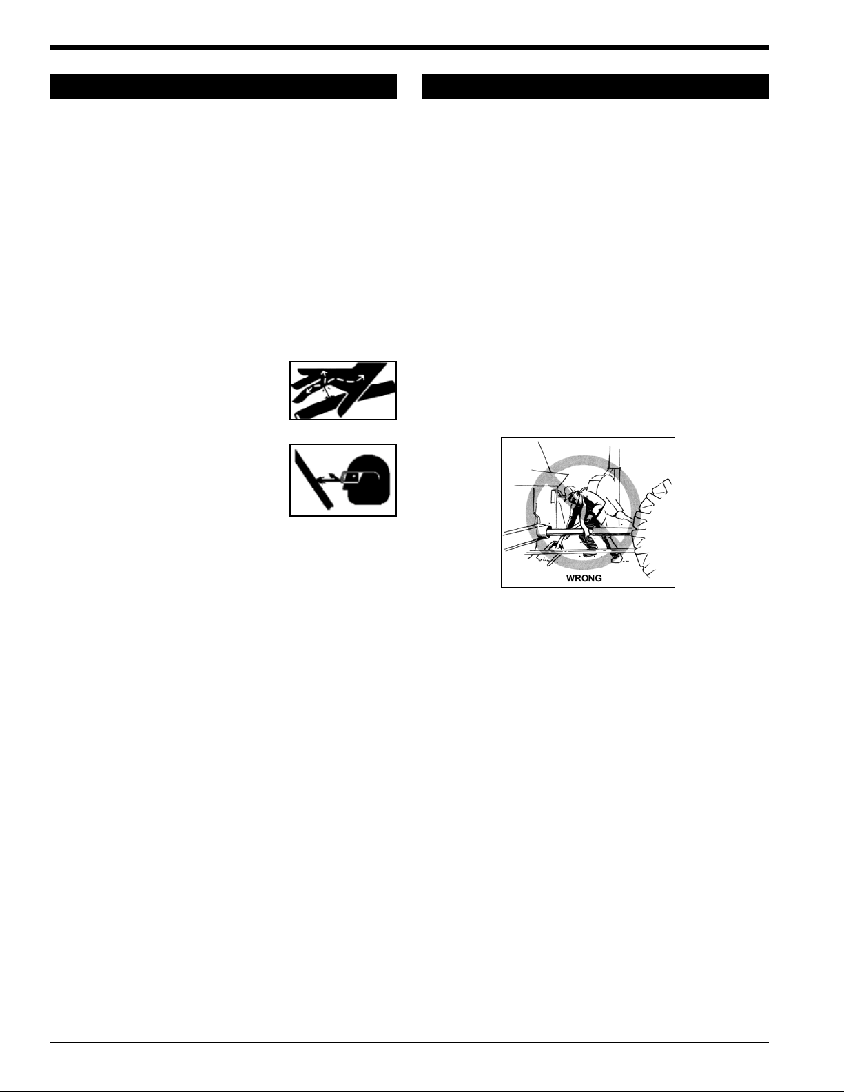
Wear proper hand and eye protection
when searching for a high-pressure
hydraulic leak. Use a piece of wood
or cardboard as a backstop instead of
hands to isolate and identify a leak.
If injured by a concentrated high-
pressure stream of hydraulic fluid,
seek medical attention immediately.
Serious infection or toxic reaction can
develop from hydraulic fluid piercing
the skin surface.
Before applying pressure to the system, make sure all com-
ponents are tight and that lines, hoses, and couplings are
not damaged.
1.
2.
3.
4.
5.
6.
7.
8.
Keep bystanders, especially children, away from
drivelines.
Be extremely careful when working around PTO shafts,
drivelines, or other rotating shafts.
Do not remove or modify protective shields or guards.
Do not step across a PTO shaft or driveline or use it as a
step.
Keep guards and shields in place at all times while operat-
ing.
Replace all damaged or missing parts or shields with the
correct original manufacturer’s parts.
Grease, clean, and maintain PTO components according
to original manufacturer’s specifications and information in
this manual.
Clothing worn by the operator must be fairly tight. Never wear
loose-fitted jackets, shirts, or pants when working around the
drivelines. Tie long hair back or put under a cap.
Keep hydraulic hoses, electrical cords, chains, and other
items from contacting the drivelines.
Do not clean, lubricate, or adjust the drivelines when the reel
is engaged and the combine is running.`
1.
2.
3.
4.
5.
6.
7.
8.
9.
10.
THINK SAFETY! WORK SAFELY!
SAFETY
2.5 HYDRAULIC SAFETY 2.6 PTO SAFETY

PN 26037-00 R070607 9
Make sure you are in compliance with all local regulations
regarding transporting equipment on public roads and
highways.
It is the responsibility of the owner to know the lighting and
marking requirements of the local highway authorities and
to install and maintain the equipment to provide compliance
with the regulations. Add extra lights when transporting at
night or during periods of limited visibility.
See the Owner’s manual that came with your combine and
header for proper transportation.
1.
2.
3.
Keep safety decals clean and legible at all times.
Replace safety decals that are missing or have become
illegible.
Replaced parts that displayed a safety decal should also
display the current decal.
Decals that need to be replaced, are to be placed back in
the original location.
Safety decals are available from your authorized dealer or
the factory.
HOW TO INSTALL SAFETY DECALS:
Be sure that the installation area is clean and dry.
Be sure temperature is above 50°F (10°C).
Decide on the exact position before you remove the back-
ing paper.
Remove the smaller portion of the split backing paper.
Align the decal over the specified area and carefully press the
small portion with the exposed sticky backing in place.
Slowly peel back the remaining paper and carefully smooth
the remaining portion of the decal in place.
Small air pockets can be pierced with a pin and smoothed
out using the piece of decal backing paper.
1.
2.
3.
4.
5.
1.
2.
3.
4.
5.
6.
7.
THINK SAFETY! WORK SAFELY!
SAFETY
2.7 TRANSPORT SAFETY 2.10 SAFETY DECALS
2.8 STORAGE SAFETY
2.9 ASSEMBLY SAFETY
Store the unit in an area away from human activity.
Do not permit children to play on or around the stored ma-
chine.
See the Owner’s manual that came with your combine and
header for proper storage.
1.
2.
3.
Assemble in an area with sufficient space to handle the larg-
est component and access to all sides of the machine
Use only lifts, cranes and tools with sufficient capacity for
the load.
When necessary, have someone assist you.
Do not allow spectators in the working area.
1.
2.
3.
4.

PN 26037-00 R070607
10
Crary Industries follows the general Safety Standards specified by the American Society of Agricultural Engineers (ASAE) and the
Occupational Safety and Health Administration (OSHA). Anyone who will be operating and/or maintaining the equipment must read
and clearly understand ALL Safety, Operating and Maintenance information presented in this manual.
Do not operate or allow anyone else to operate this equipment until such information has been reviewed. Annually review this in-
formation before the season start-up.
Make these periodic reviews of SAFETY and OPERATION a standard practice for all of your equipment. An untrained operator is
unqualified to operate this machine.
A sign-off sheet is provided for your record keeping to show that all personnel who will be working with the equipment have read and
understand the information in the owner’s manual and have been instructed in the operation of the equipment.
SIGN - OFF FORM
DATE EMPLOYEE SIGNATURE EMPLOYER SIGNATURE
SAFETY
2.11 SIGN-OFF FORM

PN 26037-00 R070607 11
Good safety requires that you familiarize yourself with the various safety decals, the type of warning and the area, or particular func-
tion related to that area, that requires your SAFETY AWARENESS.
THINK SAFETY! WORK SAFELY!
REMEMBER - If safety decals have been damaged, removed or become illegible or parts have been replaced without safety decals,
new decals must be applied. New safety decals are available from the manufacturer or an authorized dealer.
SAFETY DECALS
Section
3
PN 0732-0598-00 - Decal, Warning
PN 17423 - Decal, Danger
PN 26037-00 R070607
12
Section ASSEMBLY
4
Read all instructions to become familiar with the parts and procedure used before starting the actual work. You may refer to the parts
catalog for additional aid in assembling the CWS.
4.1 REEL ARM MOUNT
4.1.1 LEFT HAND
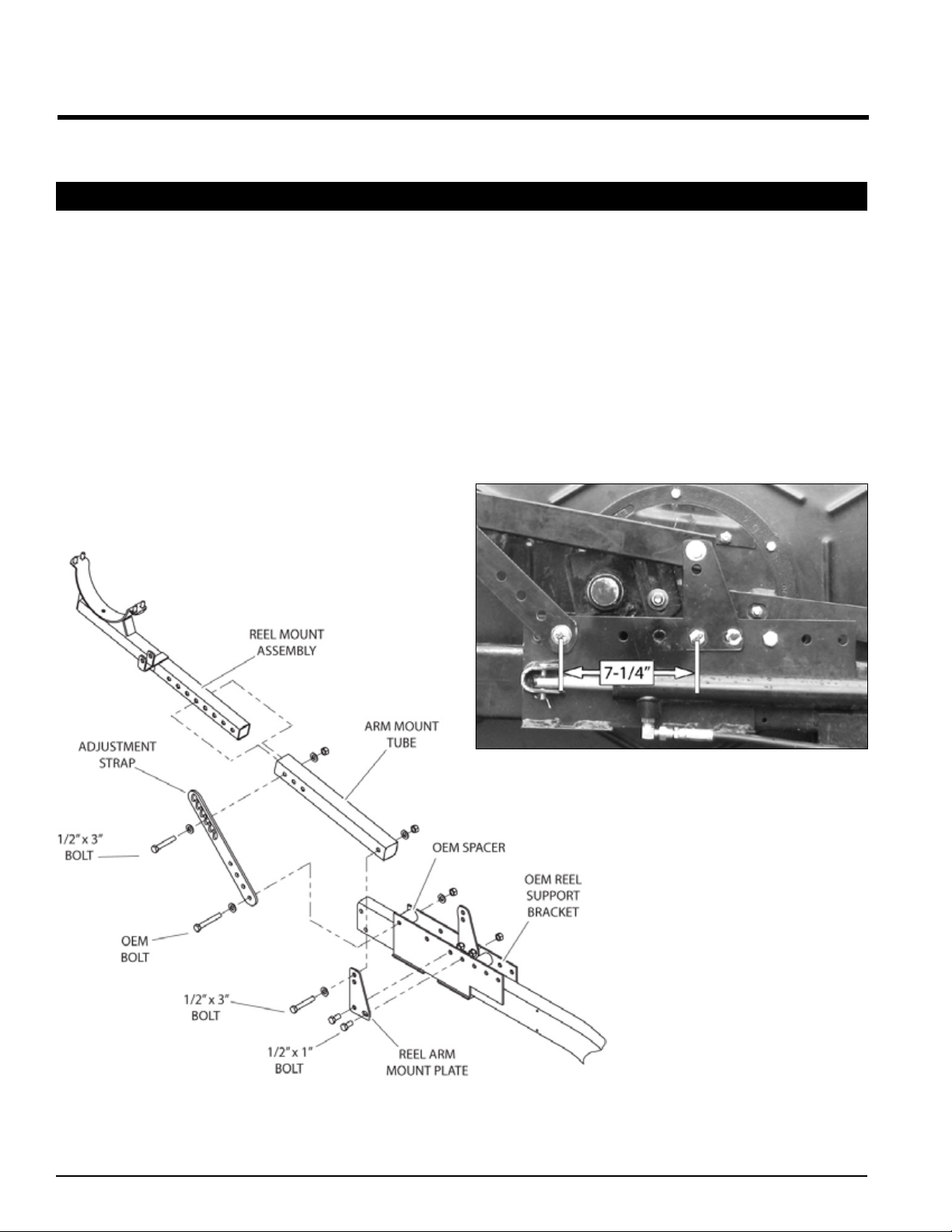
Bolt reel arm mount plates onto the OEM reel support bracket
using two 1/2” x 1” bolts and nuts per plate. Mount as shown
in Figures 1 & 2.
Measure 7-1/4” forward from the center of the mount plate
bolt shown in Figure 2. Mark and drill a 1/2” hole through the
OEM reel support bracket in this location.
Place an arm mount tube between the reel arm mount plates
and install it in the top hole with one 1/2” x 3” bolt, two wash-
ers and one nut.
Insert the LH reel mount assembly into the arm mount
tube.
1.
2.
3.
4.
Attach the notched end of the adjustment strap to the arm
mount tube and the LH reel mount with one 1/2” x 3” bolt,
two washers, and one nut. Install with the notches pointing
down.
Remove the OEM spacer at the front of the OEM reel sup-
port bracket. Use the existing 1/2” hardware to install the
bottom end of the adjustment strap and the OEM spacer in
the previously drilled hole.
Tighten all 1/2” hardware to 75 ft-lbs.
5.
6.
7.
Figure 1, Reel arm mount (left hand)
Figure 2, Reel arm mount plates

PN 26037-00 R070607 13
ASSEMBLY
4.1 REEL ARM MOUNT
4.1.2 RIGHT HAND
Bolt reel arm mount plates onto the OEM reel support bracket
using two 1/2” x 1” bolts and nuts per plate. Mount as shown
in Figure 3.
Remove the lower OEM spacer located between the reel
drive shield and shield support plate (Figure 4). It will not
be reused.
1.
2.
Place an arm mount tube between the reel arm mount plates
and install it in the top hole with one 1/2” x 3” bolt, two wash-
ers and one nut.
Insert the RH reel mount assembly into the arm mount
tube.
Attach the notched end of the adjustment strap to the arm
mount tube and the RH reel mount with one 1/2” x 3” bolt,
four washers, and one nut. Install with the notches pointing
down.
Attach the bottom end of the adjustment strap to the OEM
reel support bracket by using the existing 1/2” hardware at
the front of the reel support bracket.
Tighten all 1/2” hardware to 75 ft-lbs.
3.
4.
5.
6.
7.
Figure 3, Reel arm mount (right hand)
Figure 4, Removing the OEM spacer

PN 26037-00 R070607
14
ASSEMBLY
4.2 MANIFOLD
For sectional manifolds, bolt the RH and LH manifold
ends to the center manifold using eight 3/8” x 1-1/2”
bolts and 3/8” nylock nuts for each end. Install a baffle
plate between the sections. Make sure the air holes of
all sections are pointing the same direction and tighten
to 30 ft-lbs.
Slide a brace clamp over each end of the manifold
(Figure 5).
Center the manifold on the reel arm mounts.
Slide brace clamps out against the inside of the reel
arm mounts and tighten.
Place the half clamps on top of the manifold and con-
nect each half clamp with four 3/8” bolts and nuts. Do
not tighten nuts yet.
1.
2.
3.
4.
5.
Slide the pivot clamp on the left hand side of the mani-
fold. Loosely tighten the bolts and nuts.
Attach the electric actuator to the pivot clamp and reel
arm mount using the provided 1/2” hardware. Adjust-
ment of the pivot clamp will be made after the air tubes
have been installed.
Attach the tube cap to the LH end of the manifold.
Install a t-bolt clamp to the tube cap.
6.
7.
8.
9.
Figure 5, Setting the manifold
LEFT HAND MOUNTRIGHT HAND MOUNT

PN 26037-00 R070607 15
4.3 AIR TUBES
When installing the air tubes, start working from the LH side (as
looking from the combine cab) of the manifold and work to the
right.
Apply the self adhesive foam seals.
Remove and discard the slot and two hole cutouts
from the self adhesive foam seal.
Remove the self adhesive foam seal from the back-
ing and apply foam seal to manifold.
The first air tube installed will be a long air tube. On manifolds
that require drilling* (see table), the first air tube installed will
be a short air tube.
To connect the air tube, place it on one of the holes in the
manifold and point the end towards the direction of the
cutterbar.
Insert the U-bolt around the manifold and through the holes
on the air tube weldment (Figure 6).
Attach the air tube with two 5/16” flange nuts and flat wash-
ers. Tighten nuts to 17 ft-lbs.
Repeat procedure for all air tubes, making sure to alternate
long and short air tubes.
If your manifold requires drilling (see the manifold length ta-
ble), perform the following step. Otherwise, skip to step 8.
To mount the long end air tubes, two 1-9/16” holes must be
drilled on each end of the manifold. Drill the holes as far to
the outside of the header as possible, while still providing
room to install the air tube. Repeat the steps above to mount
the end air tubes.
Adjust the electric actuator to the middle of its stroke (ap-
prox. 2” of actuator shaft exposed) with the air tube nozzles
pointed at the sickle bar.
Make sure the reel tines do not contact the drop tubes. If
there is contact, adjust the manifold left or right within the
half clamps until the tines clear the drop tubes.
Tighten half clamps and actuator mounting hardware.
If necessary, adjust drop tube height with the adjustment
strap located on the reel arm mount.
1.
A.
B.
2.
3.
4.
5.
6.
7.
8.
9.
10.
11.
MANIFOLD LENGTH # OF SHORT
DROP TUBES
# OF LONG
DROP TUBES
* 15 FT (12” SPACING) 7 7
18 FT (12” SPACING) 8 9
* 20 FT (12” SPACING) 9 10
* 22 FT (12” SPACING) 10 11
* 25 FT (12” SPACING) 12 13
25 FT (13 5/16” SPACING) 11 12
* 30 FT (12” SPACING) 14 15
30 FT (13 5/16” SPACING) 13 14
* End holes will need to be drilled after mounting manifold.
Figure 6, Drop tube assembly
ASSEMBLY
For manifolds that require drilling, it is important that you begin
with a short drop tube. Failure to do so will result in short drop
tubes being installed on the manifold ends, which may reduce
crop feeding on the ends.
NOTE

PN 26037-00 R070607
16
ASSEMBLY
4.4 HEADER PREPARATION
Clearance of 42” is required between the outside edge of the RH
tire and the RH inside edge of the header in order to mount the
standard fan/gearbox.
A gearbox/fan extension kit can be purchased for headers smaller
than 20’ on combines with dual tires (See Section 4.15 for instal-
lation instructions).
PRE ‘93 HEADERS
No disassembly required.
‘93 AND AFTER HEADERS (15 FT - 22.5 FT)
On RH side of header, remove the driveline clutch assembly and
shielding and set aside. These components will not be used in
reassembly.
‘93 AND AFTER HEADERS (25 FT - 30 FT)
Remove the OEM PTO driveline from the auger drive
shaft.
Remove the OEM drive shaft shield and door assembly.
Remove the OEM clamp from the auger drive shaft. Then,
remove the OEM sprocket and hub from the RH end of the
drive shaft.
Take off all OEM drive shaft bearings except the far RH
bearing. Remove the OEM auger drive shaft.
Set parts aside. All removed parts will be reused except the
OEM bearings and auger drive shaft.
1.
2.
3.
4.
5.
Place all controls in neutral or off, stop combine engine, set
parking brake, remove ignition key, wait for all moving parts to
stop, then properly block machine before servicing, adjusting,
repairing, or unplugging.
WARNING

PN 26037-00 R070607 17
ASSEMBLY
THIS PAGE INTENTIONALLY LEFT BLANK.
PN 26037-00 R070607
18
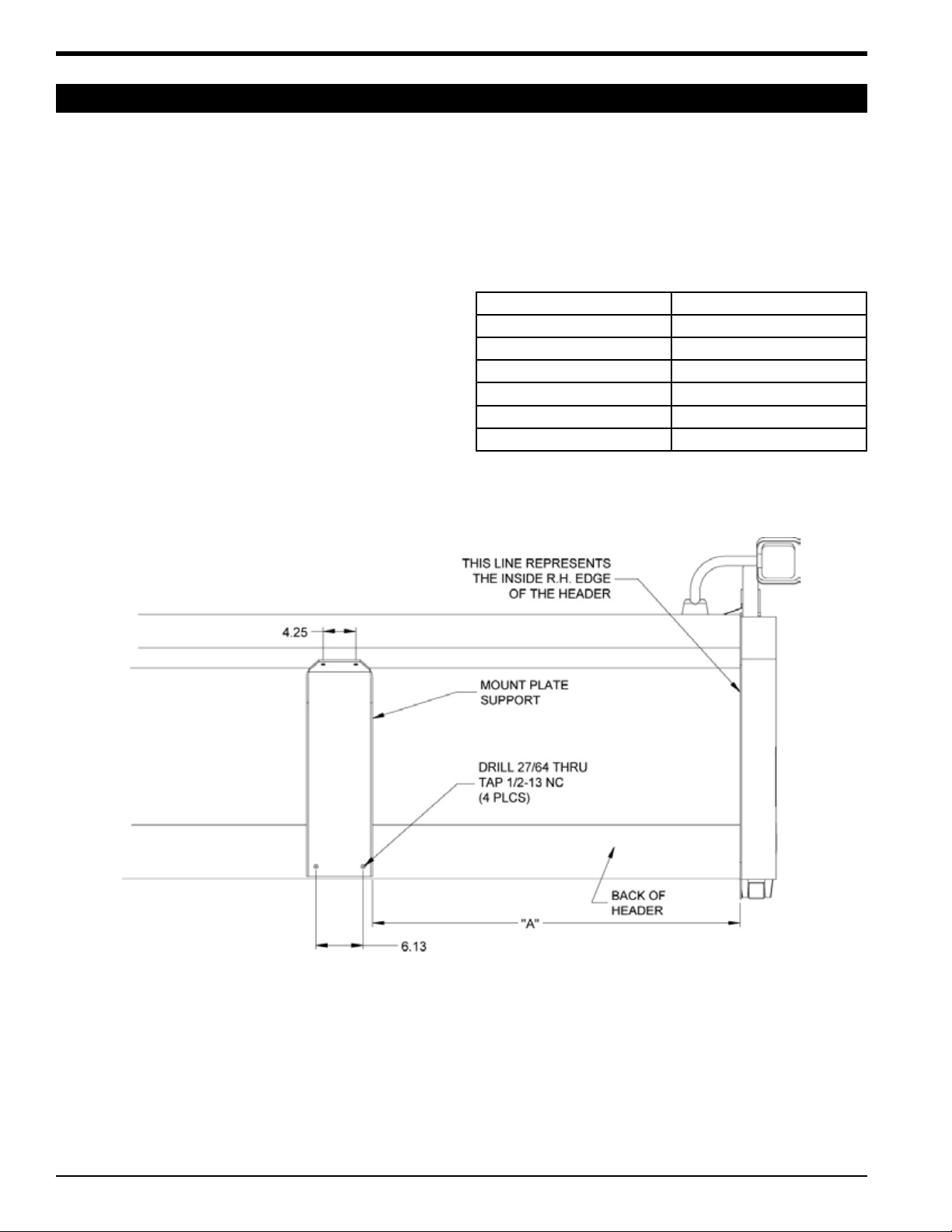
4.5 GEARBOX/FAN MOUNT - PRE 1993 SERIES
Position the mount plate support on the back of the header
as shown in Figure 7 and clamp in place. Refer to the fol-
lowing table for Dim. A.
Mark and drill the four 27/64” (.4218”) holes and tap to 1/2-13
NC for the mount plate support.
Install four 1/2” washers and bolts. Tighten to their speci-
fied torque.
Check the gearbox and if necessary, fill the gearbox with
lube before use.
Use Mobilube SHC 75W-90 synthetic gear lube or
equivalent with the following specifications:
API Service GL-5/MT.1
MIL-L-2105D
MACK GO-J PLUS
SAE J2360
Capacity: 40 oz.
1.
2.
3.
4. HEADER WIDTH DIM. “A”
15’ 9”
17-1/2’ 24”
20’ 39”
22-1/2’ 39”
25’ 54”
30’ 84”
ASSEMBLY
Figure 7, Gearbox/fan mount dimensions (Pre 1993 series)
Attach gearbox mounting plates to the mount plate support
(Figure 8). Do not tighten at this time.
Lift the gearbox/fan into position using a floor jack or over-
head hoist and secure to the support plate with four 1/2” bolts
and washers. Do not tighten at this time.
Keep gearbox/fan suspended with hoist or jack to install the
RH Drive Kit (Section 4.9).
5.
6.
7.
Other manuals for CWS 1010
1
This manual suits for next models
1
Table of contents
Other Crary Farm Equipment manuals


Popular Farm Equipment manuals by other brands


Vicon
Vicon Fanex 903 CD Assembly instructions

Betstco
Betstco Value Leader GK Series Operations & parts manual

Civemasa
Civemasa STAC M 500 Operator's manual

Unverferth
Unverferth MAXIMUS 100 Operator's manual and parts catalog

Teagle
Teagle Tomahawk 7100 Instruction book

Tektite
Tektite Toro Groundsmaster 4000-D Operation manual


