www.ashlandind.com
3
PH: 715-682-4622
Introduction
Thank you for choosing an Ashland disc harrow for your earth tilling needs.
Years of research, testing, and successful application have been spent to
ensure quality and maximum performance for our customers.
Quality Policy
It is our mission to exceed our customers’ expectations in quality, delivery, and cost
through continuous improvement and customer interaction.
Please read and understand this manual before attempting to attach or operate this
disc harrow. This manual should always remain with the machine. Be sure and fill out
and send in the owner’s registration form at the beginning of this manual, or you may
fill out the form on-line by going to ashlandind.com and click on “Owner Registration”
in the Support section drop-down. If you have questions, please feel free to call or
email us. You can visit us on-line at www.ashlandind.com.
Ashland Industries hours of operation are 8:00 a.m. to 5:00 p.m. CST. We can be
reached toll free at: 877-634-4622.
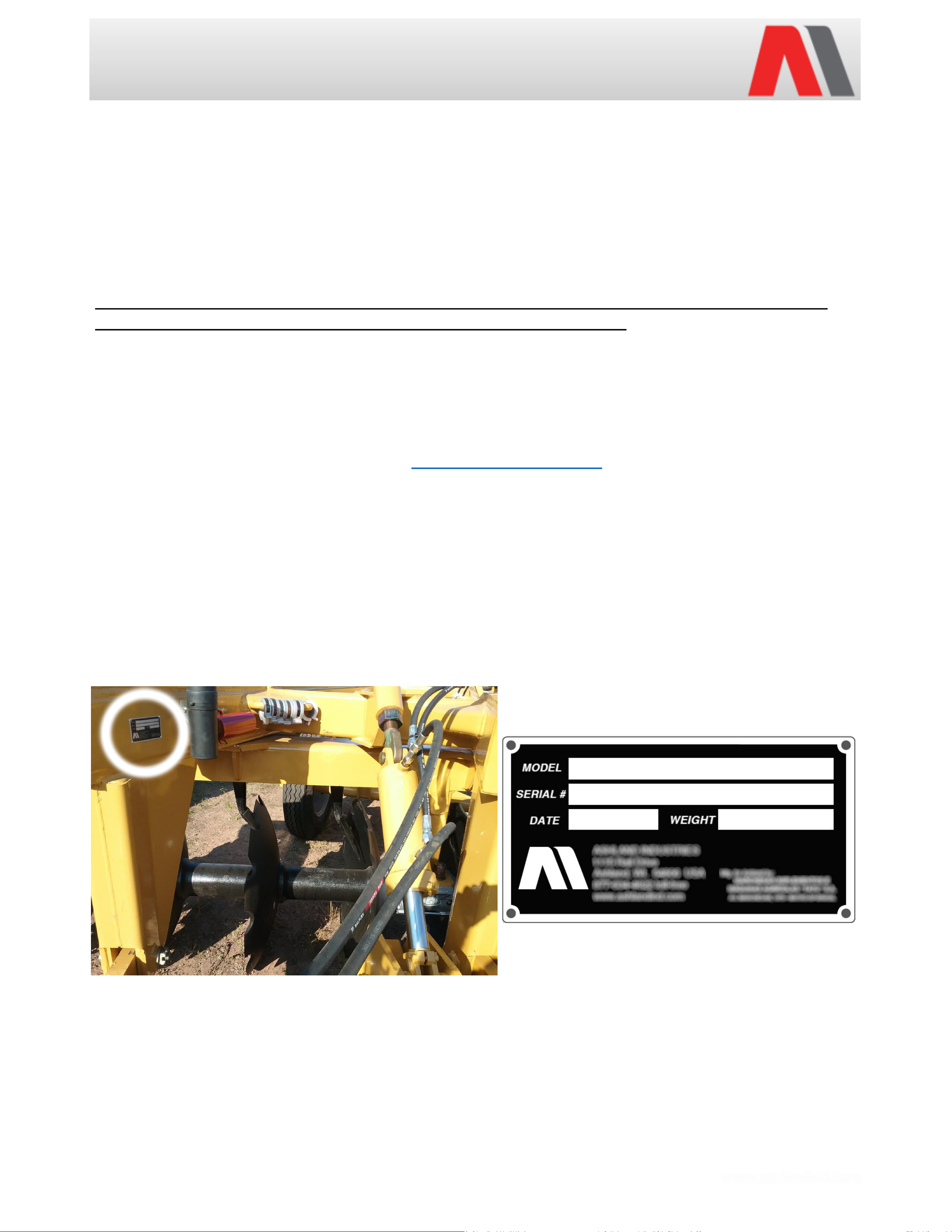
ID Number
You can find the serial number plate for most machines on the front section of the
frame along in the inner tube. The letter and numbers stamped identify the serial
number, model number, weight, and date of manufacture. Please record this serial
number for use in ordering parts, warranty issues, and to track your equipment if it is
ever stolen.
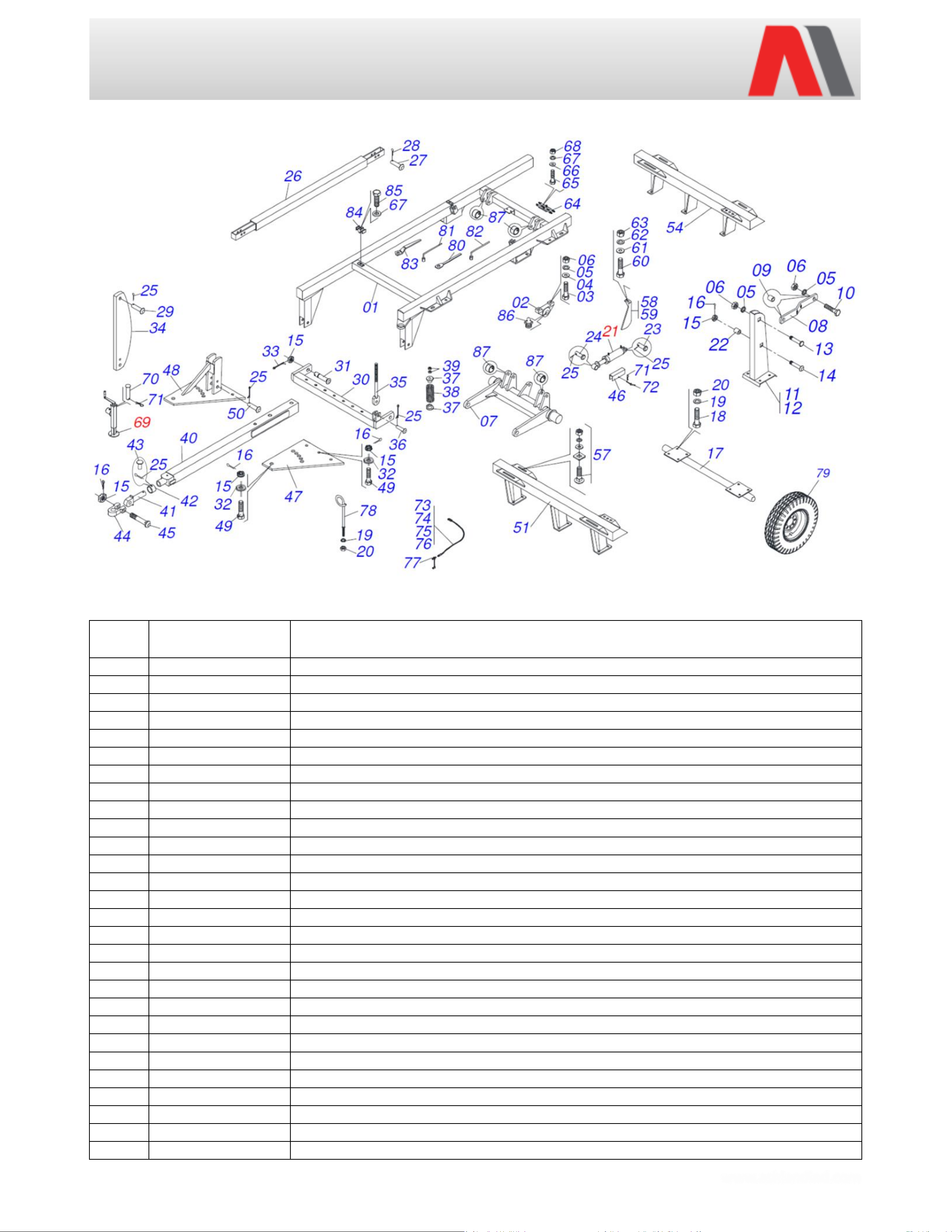
Important
Parts must be ordered through your local authorized ASHLAND dealer. Be sure to
state MODEL and SERIAL NUMBER of your machine. Ashland Industries Weldable
replacement parts are also available to rebuild, modify, or update your machine to
current factory specifications.