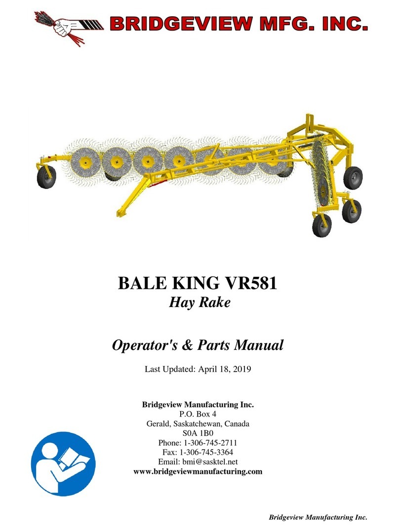
Crary Air Reel User manual

GLEANER/MASSEY FERGUSON
OWNER'S MANUAL
Manual PN 12071
Rev. 0902
Companion to 12088
GLEANER
300, 500, 800
MASSEY FERGUSON
9850

Disclaimer
This document is based on information available at the time of its publication. While efforts have been made to be accurate, the
information contained herein does not purport to cover all details or variations, nor to provide for every possible contingency in
connection with installation, operation, or maintenance. Features may be described herein which are not present in all systems.
Crary Company assumes no obligation of notice to holders of this document with respect to changes subsequently made.
The Crary Company assumes no responsibility for the accuracy, completeness, sufficiency, or usefulness of the information
contained herein. SPECIFICATIONS ANDDESIGNARESUBJECT TOCHANGEWITHOUT NOTICE.
The Crary Company is continually making improvements and developing new equipment. In doing so, we reserve the right to make
changes or add improvements to our product without obligation for equipment previously sold.
Because modification to this machine may affect the performance, function, and safety of its operation, no modifications are to be
made without the written permission of the Crary Company. Part replacements should be with original equipment supplied by the
Crary Company. THECRARYCOMPANYSTATEMENTOFPRODUCTSAFETY
“Asa manufacturerofspecialized agriculturalequipment,the CraryCompany fully recognizesits responsibilityofproviding
its customers products that perform their expected use in a reasonably safe manner. Safety considerations shall be an
integral and high priority part of all engineering/design analysis and judgments involving Crary products. It is our stated
policy that our products will be manufactured to comply with the safety standards specified by the American Society of
Agricultural Engineers, the National Electrical Code, The Society of Automotive Engineers, and/or any other applicable
recognizedstandards atthe timemanufactured. However,thisstatement shouldnotbe construedto meanthatour product
will safeguard against a customer’s own carelessness or neglect in violating common safety practices specified in each
product’s manual, nor will we be liable for any such act.”
Copyright
© 2002, Crary Company. All rights reserved. Produced and printed in the USA.
Preface
Thismanualis intended for use withthe“AirReels” for Gleaner and MFHeaders.
Revision History
Issue Date Reasons for Change
12071 7/99 Revision (See ECO Info)
12071 9/02 Revision (See ECO Info)

LIMITED WARRANTY
This warranty applies to Bear Cat, Crary, Load-N-Lift, Lockwood and Weed Roller brand products manufactured
by Crary Company, a division of TerraMarc Industries, henceforth called Crary Company.
Crary Company warrants to the original owner each new Crary Company product to be free from defects
in material and workmanship, under normal use and service. The warranty shall extend 1 year from date of
delivery for income producing (commercial) applications and 2 years from date of delivery for non-income
producing (consumer) use of the product. The product is warranted to the original owner as evidenced by a
completed warranty registration on file at Crary Company. Replacement parts are warranted for (90) days
from date of installation.
THE WARRANTY REGISTRATION MUST BE COMPLETED AND RETURNED TO CRARY COMPANY
WITHIN 10 DAYS OF DELIVERY OF THE PRODUCT TO THE ORIGINAL OWNER OR THE WARRANTY
WILL BE VOID.
In the event of a failure, return the product, at your cost, along with proof of purchase to the selling Crary
Company dealer. Crary Company will, at its option, repair or replace any parts found to be defective in material
or workmanship. Warranty on any repairs will not extend beyond the product warranty. Repair or attempted
repair by anyone other than a Crary Company dealer as well as subsequent failure or damage that may occur
as a result of that work will not be paid under this warranty. Crary Company does not warrant replacement
components not manufactured or sold by Crary Company.
This warranty applies only to parts or components that are defective in material or workmanship.
This warranty does not cover normal wear items including but not limited to bearings, belts, pulleys, filters
and chipper knives.
This warranty does not cover normal maintenance, service or adjustments.
This warranty does not cover depreciation or damage due to misuse, negligence, accident or improper
maintenance.
This warranty does not cover damage due to improper setup, installation or adjustment.
This warranty does not cover damage due to unauthorized modifications of the product.
Engines are warranted by the respective engine manufacturer and are not covered by this warranty.
Crary Company is not liable for any property damage, personal injury or death resulting from the unauthorized
modification or alteration of a Crary product or from the owner’s failure to assemble, install, maintain or operate
the product in accordance with the provisions of the Owner’s manual.
Crary Company is not liable for indirect, incidental or consequential damages or injuries including but not
limited to loss of crops, loss of profits, rental of substitute equipment or other commercial loss.
This warranty gives you specific legal rights. You may have other rights that may vary from area to area.
Crary Company makes no warranties, representations or promises, expressed or implied as to the performance
of its products other than those set forth in this warranty. Neither the dealer nor any other person has any
authority to make any representations, warranties or promises on behalf of Crary Company or to modify the
terms or limitations of this warranty in any way. Crary Company, at its discretion, may periodically offer limited,
written enhancements to this warranty.
CRARY COMPANY RESERVES THE RIGHT TO CHANGE THE DESIGN AND/OR SPECIFICATIONS
OF ITS PRODUCTS AT ANY TIME WITHOUT OBLIGATION TO PREVIOUS PURCHASERS OF ITS
PRODUCTS.
1.
2.
3.
4.
5.
6.
7.

ii AirReelOwnerOperator’s Manual
¸
HOW TO REACH US
Address
Hours
Telephone / Fax
Number
E-mail
Internet
Crary Company
Mon. - Fri.
For Partsand Service:
For Service:serv@crary.com
237 12th St. NW
8 A.M. to 5:00 P.M.
1-800-247-7335
For Part s: agsales@crary.com
P.O. Box 849
Cen t r al Ti m e
Fax: 1-701-282-9522
Visit uson the Web @
West Fargo, ND 58078-0849
www.crary.com
Please Send us your Warranty Card
Pleasetaketime to fillinthe information requested onthecard. When you send inthecompleted
cardtous, we register yourAirReeland start coverage underourlimitedwarranty.

iiiAirReelOwnerOperator’sManual
SECTION DESCRIPTION PAGE
Contents
1.0 INTRODUCTION .................................................................................................................................2
2.0 SAFETY ....................................................................................................................................3
2.1 GENERALSAFETY ....................................................................................................................4
2.2 OPERATINGSAFETY .................................................................................................................5
2.3 MAINTENANCESAFETY ............................................................................................................5
2.4 HYDRAULICSAFETY .................................................................................................................6
2.5 PTO (POWERTAKE-OFF) SAFETY ...........................................................................................6
2.6 TRANSPORTSAFETY ................................................................................................................ 7
2.7 STORAGESAFETY ....................................................................................................................7
2.8 ASSEMBLY SAFETY .................................................................................................................. 7
2.9 SAFETYDECALS .......................................................................................................................7
2.10 SIGN-OFFFORM ........................................................................................................................8
3.0 SAFETYDECALS ....................................................................................................................................9
4.0 ASSEMBLY .................................................................................................................................. 10
4.1 UNCRATING .............................................................................................................................. 10
4.2 ECCENTRICMOUNTINSTALLATION ........................................................................................ 11
4.3 IDLERGEARINSTALLATION(BACKSIDEOFMANIFOLD)...................................................... 12
4.4 REELBATARMINSTALLATION ................................................................................................ 12
4.5 IDLERGEARINSTALLATION(FRONTSIDEOF MANIFOLD) .................................................... 13
4.6 AIRTUBEINSTALLATION ......................................................................................................... 13
4.7 REELBATINSTALLATION......................................................................................................... 15
4.8 HYDRAULICMOTORINSTALLATION ........................................................................................ 16
4.9 ECCENTRICARMINSTALLATION ............................................................................................. 17
4.10 HEADERPREPARATION .......................................................................................................... 17
4.11 GEARBOXMOUNTING ............................................................................................................. 18
4.12 INSTALLINGTHE RHDRIVE(15FTHEADERS) ........................................................................ 19
4.13 INSTALLINGTHERHDRIVE (16-24FTHEADERS) .................................................................. 20
4.14 INSTALLINGTHERH DRIVE (25- 30FTHEADERS) ............................................................... 21
4.15 REELSUPPORTINSTALLATION(300HEADERS).................................................................... 22
4.16 REELSUPPORTINSTALLATION(500,800MANUAL) .............................................................. 24
4.17 REELSUPPORTINSTALLATION (500,800ELECTRIC) ............................................................ 26
4.18 REELTOHEADERINSTALLATION ........................................................................................... 27
4.19 MANIFOLDTILTINSTALLATION ................................................................................................ 28
4.20 AIRHOSEINSTALLATION......................................................................................................... 29
4.21 ELECTRICALWIRINGINSTALLATION....................................................................................... 30
5.0 OPERATION .................................................................................................................................. 31
5.1 TO THENEWOPERATOROR OWNER ................................................................................... 31
5.2 MACHINECOMPONENTS ........................................................................................................ 32
5.3 PRE-OPERATIONCHECKLIST ................................................................................................. 33
5.4 MACHINEBREAK-IN ................................................................................................................ 33
5.4.1 PRE-STARTINSPECTION ......................................................................................... 33
5.4.2 AFTEROPERATING FOR2 HOURS......................................................................... 33
5.4.3 AFTEROPERATINGFOR10 HOURS:...................................................................... 33
5.5 CONTROLS ............................................................................................................................... 34
5.6 INITIALADJUSTMENTS ............................................................................................................ 36
5.6.1 INITIALREELADJUSTMENT..................................................................................... 36
5.6.2 TINEPITCHADJUSTMENT ....................................................................................... 37
5.6.3 SLIPCLUTCH“RUNIN” ............................................................................................. 38
5.6.4 ADJUSTINGTHETORQUELIMITER ......................................................................... 39

5.7 OPERATINGHINTS ................................................................................................................... 40
5.8 OPTIONALEQUIPMENT ........................................................................................................... 41
5.8.1 AUXILIARYREELTINEKIT ....................................................................................... 41
5.8.2 GEARBOX/FAN EXTENSION .................................................................................. 42
5.9 REELSUPPORTINSTALLATIONTRANSPORTING.................................................................... 44
5.10 STORAGE................................................................................................................................. 44
6.0 SERVICEANDMAINTENANCE ........................................................................................................ 46
6.1 SERVICE .................................................................................................................................. 46
6.1.1 FLUIDSANDLUBRICANTS....................................................................................... 46
6.1.2 GREASING ............................................................................................................... 46
6.2 SERVICERECORD................................................................................................................... 47
6.3 MAINTENANCE ......................................................................................................................... 48
6.3.1 CHECKINGGEARBOXOIL LEVEL .......................................................................... 48
6.3.2 PTOLUBRICATION ................................................................................................... 48
6.3.3 TENSIONOFIDLERGEARS .................................................................................... 49
6.3.4 PLASTICECCENTRICROLLERS.............................................................................. 49
6.3.5 FANHOUSING ANDAIRHOSE................................................................................ 50
6.3.6 CHANGINGGEARLUBE .......................................................................................... 51
6.3.7 RUN-INOFFRICTIONDISCTORQUELIMITER(SLIPCLUTCH)(DRIVELINE) .......... 51
6.3.8 FANMAINTENANCE................................................................................................. 52
7.0 TROUBLE SHOOTING ............................................................................................................................. 53
8.0 SPECIFICATIONS .................................................................................................................................. 54
8.1 REEL SPECS. .......................................................................................................................... 54
8.2 FANPERFORMANCE DATA ..................................................................................................... 54
8.3 HYDRAULICMOTORDATA ....................................................................................................... 55
8.4 BOLTTORQUE.......................................................................................................................... 56
8.5 HYDRAULICFITTINGTORQUE ................................................................................................. 57
SECTION DESCRIPTION PAGE

AirReelOwnerOperator’sManual iv
BOX 6: AIR MANIFOLD ASSY & BATS
MANIFOLD,F.A.R.
REELBAT ASSEMBLIES(6)
BOX 3: FAR BOX OF PARTS 6 BAT
MOTOR,HYD.GEAR
FOAMSEALS-AIRTUBE
PIVOTSTRAPBUSHINGS
SHAFT COUPLER
AIRTUBEWELDMENTS
IDLERGEARASSEMBLIES
REELBAT ARM ASSEMBLIES
BOX 1: FAN KIT (PART # 22667)
GEARBOX/FANASSY8.829:1
ELECTRICACTUATORMINI W/PLUG
SWITCH/MOUNTPLATE ASSY
FLEXHOSECHAINASSY
ELBOW, RUBBER 8” X 90°
T-BOLTCLAMPS
ELBOW, RUBBER-8" X 45°
FLEXHOSE/BANDASSY.
TUBECAP
MISC.HARDWARE
BOX 2: REEL ARM MOUNT KIT (PART # 23900)
FAROWNER’SMANUAL
FARPARTSMANUAL
CARD,AGWARRANTY/REGISTRATION
HARNESS,ACTUATORSWITCHADAPTER
ELECTRICACTUATOR
HOSE CONNECTOR WELDMENTS
BOX 4: GEARBOXMOUNT/DRIVE (PART # 22677,OR 22678)
BUSHINGS, SD 1-3/8" (2)
ADAPTERS,- 10 MORING /-10MJIC (2)
MOUNTPLATE SUPPORT
GEARBOXMOUNTPLATES (2)
SHIELD WELDMENTS (2)
MISC.HARDWARE
INSPECTION AFTER DELIVERY
Inspectyourshipping cartons for damage. If you suspectanydamage, contact the carrier (trucking company)rightaway.
Unpacktheshipping cartons and compare thecontentswiththe parts listing on thepackingslips. If any parts are missing
ordamaged, contactyour localauthorized dealerorcall thefactory forassistance. NOTE: Depending onheader variations,
you may or may not receive all crates and or boxes listed below.
ADJUST BRKT. WELDMENTS (2)
HALFCLAMPS(2)
REEL SUPT. PAD-RH & LH
ASSEMBLY,PIVOTCLAMP
REEL SUPPORT ASSY LH & RH
MISC.HARDWARE
T-BOLTCLAMPS
ECCENTRICARM ASSY’S (2)
DOUBLEAIR TUBE ASSEMBLIES (2)
BRACECLAMPASSEMBLIES(2)
WRENCH,ADJUSTMENT
RH & LH ECCEN. MT. ASSEMBLIES
MISC.HARDWARE
BOX 5: BOX 2 OF 3
DRIVELINE/ C-FLANGE
ASSY.
BOX 5: BOX 3 OF 3
GEARBOXDRIVESHAFT
DRIVESHAFT SHIELD
BOX 5: RH DRIVE SHAFT KIT
BOX 5: BOX 1 OF 3
SLIP CLUTCH SHIELD
SHIELDMOUNTPLATEASSY.
DRIVESHAFTSHIELD-JACKSHAFT
BEARINGINSERTS
CLUTCH SHAFT WELDMENT - HEX
SLIP CLUTCH SHIELD WELDMENT
SHIELD MOUNT BRACKETS (2)
CHAIN COUPLER
DRIVESPROCKETS
DRIVELINESUPPORT BRACKET
MISC.HARDWARE
BOX1OF 3 BOX 2 OF3 BOX3OF 3


Page1AirReelOwnerOperator’sManual
SERIAL NUMBER LOCATION
Always give your dealer the serial number of your Crary Air Reel when ordering parts, requesting service or any other
information.
The serial number decal is located on the front, left hand end of the Air Reel manifold. Please record the serial number in
thespaceprovided below (using stickeronmanifold)and on the warrantyandregistrationcard (using other sticker).
REPLACEMENT PARTS
Onlygenuine CraryCo. replacementparts shouldbe usedtorepairthemachine. CraryCo.replacement partsare available
fromyour CraryCo. Dealer. Toobtain prompt,efficientservice,remember togive thedealerthecorrectpart descriptionand
serialnumberof the machine.
Please be sure to provide the following information:
1. TheSERIAL NUMBER of yourAirReel.
2. ThePART NUMBERofthe part.
3. ThePARTDESCRIPTION.
4. TheQUANTITYneeded.
Serial Number ________________________
WARNING
Place all controls in neutral or off, lower header to the
ground,stopcombineengine,setparkingbrake,chock
wheels,remove ignitionkey,waitfor allmoving partsto
stop,before obtainingserialnumber,servicing,adjust-
ing,repairing orunplugging.
Fig #3, Location of stickers
Also two serial number stickers are included with each Air
Reel. The decals are located on the packaged Air Reel
manifold. One sticker is to be placed on the warranty
registration card and mailed back to Crary Company. The
secondstickeris to be placedabovefor future reference.
Fig. #2 Serial number decal
YXXXXX
Fig. #1 Serial number decal location
(place sticker here)

Page2 AirReelOwnerOperator’sManual
1.0 INTRODUCTION
Congratulations on your choice of a new Crary Air Reel to complement your farming operation. This equipment has been
designedandmanufactured to meettheneeds of a discerningagriculturalindustry for the efficientharvestingof crops.
Safe, efficient, and trouble free operation of your Air Reel requires that you and anyone else who will be operating or
maintaining the machine, read and understand the Safety, Operation, Maintenance, and Trouble Shooting information
containedwithinthe Operator’s Manual. Check eachitemreferred to and acquaintyourselfwith the adjustments required
toobtain efficient operation.
Thismanual coversall Modelsofthe AirReel manufacturedbyCrary Companyfor Gleaner series300,500, &800 and MF
9850 headers. Differences are covered and explained where appropriate. Use the table of contents as a guide to locate
requiredinformation.
Keep this manual handy for frequent reference and to pass on to new operators or owners. Call your Crary dealer or
distributor if you need assistance, information, or additional copies of the manuals.
Manypeople haveworked onthedesign, production,and deliveryofthis machine. Theyhave builtintoit thehighest quality
ofmaterialsand workmanship. The information inthismanual is based ontheknowledge,study,and experience ofthese
peoplethrough years ofmanufacturing specialized farmingmachinery.
Theperformanceofthemachinedependsonpropermaintenanceandadjustment. Evenifyouareanexperiencedoperator
ofthis orsimilarequipment, weask youtoread theoperator’s manualbeforerunning themachine. Keep themanualhandy
for future reference. It has been carefully prepared, organized, and illustrated to assist you in finding the information you
need. Your Crary dealer willbehappytoansweranyfurther questions you may have about the machine.
OPERATOR ORIENTATION - All references to left, right, front and rear of the machine, as mentioned throughout the
manual,are determined bystandingbehind the machineandfacing towards thedirectionof forward travel.

Page3AirReelOwnerOperator’sManual
This Safety Alert Symbol means
ATTENTION!BECOME ALERT!
YOURSAFETY ISINVOLVED!
The Safety Alert symbol identifies important
safetymessagesonthe Crary Air Reel and in
the manual. When you see this symbol, be
alert to the possibility of personal injury or
death. Follow the instructions in the safety
message.
DANGER- Indicates an imminently hazardous
situation that, if not avoided, will re-
sult in death or serious injury. This
signalword isto belimited tothe most
extreme situations, typically for ma-
chinecomponentsthat, for functional
purposes,cannot beguarded.
WARNING- Indicatesapotentiallyhazardoussitu-
ation that, if not avoided, could result
indeathor seriousinjury,andincludes
hazards that are exposed when
guards are removed. It may also be
usedtoalertagainstunsafe practices.
CAUTION- Indicatesa potentiallyhazardous situ-
ationthat, ifnot avoided,mayresultin
minorormoderateinjury. Itmayalso
be used to alert against unsafe prac-
tices.
IMPORTANT- Instructions that must be followed to
ensureproperinstallation/operation of
equipment.
NOTE - General statements to assist the
reader
2.0 SAFETY SAFETY ALERT SYMBOL
Why is SAFETY important to you?
Accidents Disable and Kill
3 Big Reasons Accidents Cost
Accidents Can Be Avoided
SIGNAL WORDS:
Notethe use ofthesignal wordsDANGER,WARN-
ING, CAUTION, IMPORTANT and NOTE with the
safety messages. The appropriate signal word for
each message has been selected using the follow-
ingguidelines:

Page4 AirReelOwnerOperator’sManual
2.0 SAFETY
YOU are responsible for the SAFE operation and mainte-
nance of your Crary Air Reel. YOU must ensure that you
and anyone else who is going to operate, maintain or work
aroundtheCraryAirReelarefamiliar withthe operatingand
maintenance proceduresand related SAFETYinformation
contained in this manual. This manual will alert you to all
goodsafetypracticesthatshouldbeadheredtowhileoperat-
ing the Crary Air Reel.
Remember, YOU are the key to safety. Good safety prac-
tices not only protect you but also the people around you.
Make these practices a working part of your safety pro-
gram. Be certain that EVERYONE operating this equip-
mentis familiarwith therecommendedoperating andmain-
tenanceproceduresand follows all the safetyprecautions.
Most accidents can be prevented. Do not risk injury or
deathbyignoring good safety practices.
• CraryAir Reel ownersmustgive operating instructions
tooperatorsor employees before allowing them toop-
eratethemachine, and at least annuallythereafterper
OSHA(OccupationalSafetyandHealth Administration)
regulation1928.57.
• The most important safety device on this equipment is
a SAFE operator. It is the operator’s responsibility to
readandunderstand ALLSafetyand Operatinginstruc-
tions in the manual and to follow them. All accidents
canbeavoided.
• A person who has not read and understood all operat-
ing and safety instructions is not qualified to operate
the machine. An untrained operator exposes himself
and bystanders to possible serious injury or death.
• Donotmodify the equipmentin anyway. Unauthorized
modificationmayimpair the function and/orsafetyand
couldaffectthe life of the equipment.
• ThinkSAFETY!WorkSAFELY!
2.1 GENERAL SAFETY
1. Read and understand the
Operator’s Manual and all
safetysigns beforeoperat-
ing,maintaining,adjusting
or servicing the Crary Air
Reel.
2. Only trained persons shall
operatetheCrary Air Reel. An untrained operator is
notqualifiedto operate themachine.
3. Have a first-aid kit available for use should the need
arise and know how to use it.
4. Provide a fire extinguisher for use
in case of an accident. Store in a
highlyvisible place.
5. Donot allowchildren,spectatorsorby-
standers within hazard area of ma-
chine.
6. Wearappropriateprotectivegear. This
list Includes but is not limited to:
- A hard hat
- Protectiveshoes
with slip resistant soles
- Protective goggles
- Heavygloves
- Hearingprotection
- Respiratoror filter
mask
7. Wearsuitable ear protection forprolongedexposure
to excessive noise.
8. Placeall controlsinneutral
or off, lower header to the
ground, stop combine en-
gine, set parking brake,
chockwheels, removeigni-
tionkey, wait for all moving
partsto stop,before servic-
ing, adjusting, repairing or
unplugging.
9. Reviewsafety relateditemsannually withallperson-
nelwho will beoperatingor maintainingtheCrary Air
Reel.

Page5AirReelOwnerOperator’sManual
2.3 MAINTENANCE SAFETY
1. FollowALL the operating, maintenance, and safetyin-
formationin the manual.
2. Supportthe machinewithblocks orsafety standswhen
workingaround it.
3. Followgoodshop practices:
•Keepservice area
clean and dry.
•Be sure electrical
outlets and tools are
properlygrounded.
•Useadequate light
for the job at hand.
4. Use only tools, jacks and hoists of sufficient capacity
forthejob.
5. Place all controls in neutral or off, lower header to the
ground,stop combineengine,set parkingbrake, chock
wheels,remove ignition key, waitfor all movingparts to
stop, before servicing, adjusting, repairing or unplug-
ging.
6. Beforeresumingwork,installandsecureallguardswhen
maintenanceworkis completed.
7. Relievepressure fromhydrauliccircuit beforeservicing
ordisconnecting from combine.
8. Keephands,feet, hair and clothingawayfrom all mov-
ingand/orrotating parts.
9. Clearthe area ofbystanders, especially smallchildren,
whencarryingoutanymaintenance andrepairsormak-
ing any adjustments.
10. Keep safety decals clean. Replace any decal that is
damagedor not clearly visible.
11. First-classmaintenance is a prerequisite forthesafest
operationofyour machine. Maintenance, includinglu-
brications, should be performed with the machine
stopped and locked out.
2.2 OPERATING SAFETY
1. Readand understand the Owner /Operator’sManual
andallsafety decals before servicing, adjusting orre-
pairing.
2. Install and secure all guards and shields before start-
ingor operating.
3. Keephands, feet,hairand clothingaway fromallmov-
ingand/orrotating parts.
4. Place all controls in neutral or off, lower header to the
ground,stopcombineengine,set parkingbrake,chock
wheels,removeignitionkey,waitforallmovingpartsto
stop, before servicing, adjusting, repairing or unplug-
ging.
5. Clearthe areaof bystanders,especially smallchildren,
beforestarting.
6. Keepall hydrauliclines,fittings, andcouplers tightand
freeof leaks beforeandduring use.
7. Cleanreflectors and lightsbefore transporting.
8. Reviewsafety relateditems annuallywith allpersonnel
whowillbeoperatingormaintainingtheCraryAir Reel.
9. Shut the combine off when connecting the machine
hydraulics.
10. Do notexceed fan speedof 5300RPM. Checkthe fan
speed by multiplying the drive shaft speed (RPM) by
thegearratio of the gearbox.
11. Do not run the fan without back pressure. Close the
butterflyvalveonthefaniftheflexhoseisdisconnected.

Page6 AirReelOwnerOperator’sManual
2.4 HYDRAULIC SAFETY
1. Always place all combine hydraulic controls in neu-
tralbefore disconnectingfrom combineor workingon
hydraulic system.
2. Make sure that all components in the hydraulic sys-
tem are kept in good condition and are clean.
3. Relievepressure beforeworkingonthehydraulic sys-
tem.
4. Replaceany worn,cut, abraded,flattened orcrimped
hoses.
5. Donot attemptanymakeshift repairstothe hydraulic
fittings or hoses by using tape, clamps or cements.
Thehydraulicsystemoperatesunderextremelyhigh-
pressure. Suchrepairs willfail suddenlyand createa
hazardousand unsafecondition.
6. Wearproperhandandeyepro-
tection when searching for a
high-pressure hydraulic leak.
Use a piece of wood or card-
boardas abackstopinstead of
hands to isolate and identify a
leak.
7. If injured by a concentrated
high-pressurestreamofhydrau-
licfluid, seekmedicalattention
immediately. Serious infection
or toxic reaction can develop
fromhydraulicfluid piercingthe
skin surface.
8. Before applying pressure to the system, make sure
all components are tight and that lines, hoses, and
couplingsare not damaged.
• ThinkSAFETY!WorkSAFELY!
2.5 PTO (POWER TAKE-OFF)
SAFETY
1. Keepbystanders,especiallychildren,awayfromdrive
shafts.
2. Be extremely careful when working around PTO
shafts,drivelines,or other rotating shafts.
3. Donot removeor modifyprotectiveshieldsorguards.
4. Do not step across a PTO or driveline or use it as a
step.
5. Keep guards and shields in place at all times while
operating.
6. Replaceall damaged ormissing parts orshieldswith
thecorrect original manufacturer’s parts.
7. Grease, clean, and maintain PTO components ac-
cordingto original manufacturer’s specificationsand
informationinthis manual.
8. Clothingwornby operator mustbefairly tight. Never
wearloose-fitting jackets,shirts,orpantswhen work-
ingaroundthe drive shafts. Tie longhairback or put
underacap.
9. Keep hydraulic hoses, electric cords, chains, and
otheritemsfrom contacting the drive shafts.
10. Donotclean,lubricate, oradjustthe driveshaftswhen
the reel is engaged and the combine is running.

Page7AirReelOwnerOperator’sManual
2.6 TRANSPORT SAFETY
1. Make sure you are in compliance with all local regu-
lations regarding transporting equipment on public
roadsand highways.
2. It is the responsibility of the owner to know the light-
ing and marking requirements of the local highway
authoritiesand to install andmaintainthe equipment
to provide compliance with the regulations. Add ex-
tralights when transportingatnight orduringperiods
of limited visibility.
3. SeetheOwnerOperator’sManualthatcamewithyour
combineand headerfor propertransportation.
2.7 STORAGE SAFETY
1. Store the unit in an area away from human activity.
2. Donot permitchildren toplayon oraround thestored
machine.
3. SeetheOwnerOperator’sManualthatcamewithyour
combineand headerfor properstorage.
2.8 ASSEMBLY SAFETY
1. Assemble in an area with sufficient space to handle
the largest component and access to all sides of the
machine
2. Useonlylifts, cranes and tools withsufficientcapac-
ity for the load.
3. When necessary, have someone assist you.
4. Do not allow spectators in the working area.
5. Be sure to read the maintenance safety section.
2.9 SAFETY DECALS
1. Keep safety decals clean and legible at all times.
2. Replacesafety decalsthat aremissing orhave become
illegible.
3. Replaced parts that displayed a safety decal should
also display the current decal.
4. Decalsthat need to bereplaced,are to be placedback
in the original location. (See section 3.0 SAFETY DE-
CALS, for correct placement of safety decals).
5. Safetydecals areavailable fromyour authorizeddealer
or the factory.
How to Install Safety Decals:
• Be sure that the installation area is clean and dry.
• Besure temperature isabove 50°F (10°C).
• Decide on the exact position before you remove the
backingpaper.
• Removethe smallest portionof the splitbacking paper.
• Align the decal over the specified area and carefully
press the small portion with the exposed sticky back-
ing in place.
• Slowly peel back the remaining paper and carefully
smooth the remaining portion of the decal in place.
• Small air pockets can be pierced with a pin and
smoothed out using the piece of decal backing paper.

Page8 AirReelOwnerOperator’sManual
2.10 SIGN-OFF FORM
The Crary Company follows the general Safety Standards specified by the American Society of Agricultural Engineers
(ASAE)and the OccupationalSafety and HealthAdministration (OSHA). Anyone whowill be operatingand/ormaintaining
the equipment must read and clearly understand ALL Safety, Operating and Maintenance information presented in this
manual.
Donotoperate or allowanyoneelse to operate thisequipmentuntil such information hasbeenreviewed. Annually review
thisinformation before the seasonstart-up.
Make these periodic reviews of SAFETY and OPERATION a standard practice for all of your equipment. We feel that an
untrainedoperator is unqualified tooperate this machine.
Asign-off sheet isprovidedfor your recordkeeping to showthatall personnel whowillbe workingwiththe equipment have
readand understand theinformationin the Operator’sManual and havebeeninstructed in theoperation of theequipment.
SIGN - OFF FORM
DATE
EMPLOYEES SIGNATURE
EMPLOYERS SIGNATURE

Page9AirReelOwnerOperator’sManual
KEEP HANDS
AWAY WHILE UNIT
IS OPERATING
WARNING
3.0 SAFETY DECALS
The types of safety decals and locations on the equipment are shown in the picture below. Good safety requires that you
familiarizeyourselfwith the various safety decals, thetypeofwarning, and the particular function relatedtotheareas that
requireyourSAFETY AWARENESS.
• Think SAFETY! Work SAFELY!
REMEMBER- Ifsafety decalshave beendamaged, removed,become illegibleorpartsreplacedwithoutsafetydecals, new
decalsmust be applied. Newsafetydecals are available fromthe manufacturer or anauthorizeddealer.
Part # 11001
Part # 11002
AB
Fig. # 4 Decal locations
1. READ AND UNDERSTAND THE OPERATOR'S MANUAL
BEFORE OPERATING.
2. KEEP ALL SAFETY SHIELDS AND DEVICES IN PLACE.
3. MAKE CERTAIN EVERYONE IS CLEAR OF EQUIPMENT
BEFORE OPERATING.
4. KEEP HANDS, FEET AND CLOTHING AWAY FROM
MOVING PARTS.
5. SHUT OFF POWER TO ADJUST, SERVICE OR CLEAN.
6. FAILURE TO ADHERE TO THESE, AND OTHER SAFETY
WARNINGS, MAY CAUSE SERIOUS INJURY.
CRARY CO.-FARGO, ND

Page10 AirReel OwnerOperator’sManual
4.0 ASSEMBLY
Read all instructions to become familiar with the parts and
procedureused before starting theactualwork.
You may refer to the Crary Air Reel parts catalog for addi-
tional aid in assembling the Air Reel.
4.1 UNCRATING
1. Locate the manifold and bats crate.
2. Cutthe metalbandsandremovethe2’X 4’sand saddle
tops. (See fig. # 5)
3. Removethe batassemblies fromthecrate andplace to
the side.
ASSEMBLY SAFETY
1. Assemble in an area with sufficient space to
handlethelargest component andaccessto all
sides of the machine
2. Use only lifts, cranes and tools with sufficient
capacity for the load.
3. When necessary, have someone assist you.
4. Do not allow spectators in the working area.
5. Besureto read themaintenancesafety section
Fig. # 5 Manifold and bats crate
4. Remove the lag screws from the mounting clamps (as
shown in Fig # 6) from all locations.
5. Usinganoverheadhoistandanylonstrap,slingorchain,
connect to the center of the manifold (See Fig. # 7).
6. Remove from crate, and set down on two steel saw-
horses(or equivalent) two tofourinches from the ends
ofthe manifold.
A. The sawhorses must be capable of supporting 500
poundseach.
B. The sawhorses must be at least 3 feet high.
Fig. # 6 Manifold and bats crate
Fig. # 7 Lift center of manifold
IMPORTANT
The sawhorses must be blocked, to keep the manifold
fromrolling.

Page11AirReelOwnerOperator’sManual
4.2 ECCENTRIC MOUNT INSTALLA-
TION
1. OpenBox # 3 andsortbolts according totheirsize and
length.
2. Rotatethe manifoldon thestands sothat thedriveshaft
is at the 12:00 position.
3. Assemble theR.H.&L.H.Eccentric MountPlates (with
thenylonrollers facing to the center ofthemanifold) to
theR.H.& L.H. End Clamps using six(Qty. 6) 3/8”X1”
carriage bolts, twelve (Qty. 12) 3/8” SAE flat washers
and six (Qty. 6) 3/8” center locknuts. Do not tighten
yet. (See Fig. # 8 & 9).
4. Alignthe 5th tooth on theR.H.&L.H. eccentric mount-
ingplate assemblieswith theindicator markon theR.H.
& L.H. end clamps.
5. Tighten the six (Qty. 6) 3/8” center locknuts to their
specifiedtorque.
NOTE
Thedefault pitch angle iswiththe 5th tooth onthe eccen-
tric mounting plate assembly aligned with the indicator
mark on the R.H. & L.H. End Clamps.
NOTE
Theback sideofthe manifoldisopposite thatof thelarge
ReelDecal.
NOTE
Do not tighten the nuts for the nylon rollers yet. (See
Fig. # 10)
Fig. # 8 R.H. Eccentric mounting plate assy.
R.H. ECCENTRIC
MT. PLATE
DO NOT
TIGHTEN YET
Fig. # 10 Do not tighten nuts yet
Fig. # 9 L.H. Eccentric mounting plate assy.

Page12 AirReel OwnerOperator’sManual
4.3 IDLER GEAR INSTALLATION
(BACK SIDE OF MANIFOLD)
1. Assembleone (Qty.1) idler gearassemblyeachto the
R.H. & L.H. end clamps, and to all idler mount clamps
(backside of manifoldonly)using one (Qty. 1) 3/8”X2”
bolt,three(Qty.3) 3/8” flat washers and one(Qty. 1) 3/
8” center locknut per each idler gear assembly. (See
Fig. # 11 & 12).
2. Tightenthe 3/8” center locknuts to theirpropertorque.
4.4 REEL BAT ARM INSTALLATION
1. Slide the reel bat arm assemblies over the manifold
assembly. Positioneachassemblyontothepiniongears
andthe idler gearsof the manifoldassembly. (SeeFig.
#13)
2. Align the reel bat arm assemblies, so that all of the
armsare in-line with oneanother.
Fig. # 12 Idler gear assembly to idler clamp assembly
IMPORTANT
Theoutsideface of the armsofthereel bat arm assem-
blies must face away from the pillowblock.
Fig. # 11 Idler gear assembly to R.H end clamp assembly
Fig. # 13 Reel bat arm assembly to manifold
Other manuals for Air Reel
2
Table of contents
Other Crary Farm Equipment manuals
