Crary Air Reel 1010 User manual

RECORD SERIAL NUMBER HERE
OWNER’S MANUAL
Manual P/N 12069
Rev. 072208
Companion to P/N 12086
SN Range: 709608-Current
CASE IH
1010
1020

DISCLAIMER
This document is based on information available at the time of its publication. While efforts have been made to be accurate, the
information contained herein does not purport to cover all details or variations, nor to provide for every possible contingency in con-
nection with installation, operation, or maintenance. Features may be described herein which are not present in all systems. Crary
Industries assumes no obligation of notice to holders of this document with respect to changes subsequently made.
herein.
SPECIFICATIONS AND DESIGN ARE SUBJECT TO CHANGE WITHOUT NOTICE.
Crary Industries is continually making improvements and developing new equipment. In doing so, we reserve the right to make
changes or add improvements to our product without obligation for equipment previously sold.
made without the written permission of Crary Industries. Part replacements should be with original equipment supplied by Crary
Industries.
THE CRARY INDUSTRIES STATEMENT OF PRODUCT SAFETY
As a manufacturer of specialized agricultural equipment, Crary Industries fully recognizes its responsibility of providing its customers
products that perform their expected use in a reasonably safe manner. Safety considerations shall be an integral and high prior-
ity part of all engineering/design analysis and judgments involving Crary products. It is our stated policy that our products will be
this statement should not be construed to mean that our product will safeguard against a customer’s own carelessness or neglect in
SERIAL NUMBER LOCATION
Always give your authorized Crary dealer the serial number of
your machine when ordering parts, requesting service, or any
other information. The serial number decal is located on the front,
left hand end of the air manifold.
Please record the serial number in the space provided on the front
cover and on the warranty and registration card.
© 2008, Crary Industries, All rights reserved. Produced and printed in the USA.
HOW TO REACH US
ADDRESS HOURS TELEPHONE
FAX NUMBER E-MAIL
INTERNET
Crary Industries
237 12th St. NW
P.O. Box 849
West Fargo, ND 58078-0849
Mon. - Fri.
8 A.M to 5 P.M.
Central Time
For Parts and Service:
1-800-247-7335
Fax: 1-701-282-9522
For Service: serv@crary.com
Visit us on the web @
www.crary.com
.
XXXXXX
Serial Number Decal

PN 12069 R072208 iii
LIMITED WARRANTY
Crary Industries warrants to the original owner each new Crary Industries product to be free from defects
in material and workmanship, under normal use and service. The warranty shall extend 1 year from date of
delivery for income producing (commercial) applications and 2 years from date of delivery for non-income
producing (consumer) use of the product. The product is warranted to the original owner as evidenced by a
completed warranty registration on file at Crary Industries. Replacement parts are warranted for (90) days
from date of installation.
THE WARRANTY REGISTRATION MUST BE COMPLETED AND RETURNED TO CRARY INDUSTRIES
WITHIN 10 DAYS OF DELIVERY OF THE PRODUCT TO THE ORIGINAL OWNER OR THE WARRANTY
WILL BE VOID.
In the event of a failure, return the product, at your cost, along with proof of purchase to the selling Crary
Industriesdealer. CraryIndustrieswill, at itsoption,repairorreplaceanypartsfoundto be defectiveinmaterial
or workmanship. Warranty on any repairs will not extend beyond the product warranty. Repair or attempted
repair by anyone other than a Crary Industries dealer as well as subsequent failure or damage that may occur
as a result of that work will not be paid under this warranty. Crary Industries does not warrant replacement
components not manufactured or sold by Crary Industries.
This warranty applies only to parts or components that are defective in material or workmanship.1.
This warranty does not cover normal wear items including but not limited to bearings, belts, pulleys, filters and chip-2. per knives.
This warranty does not cover normal maintenance, service or adjustments.3.
This warranty does not cover depreciation or damage due to misuse, negligence, accident or improper mainte-4. nance.
This warranty does not cover damage due to improper setup, installation or adjustment.5.
This warranty does not cover damage due to unauthorized modifications of the product.6.
7.
CraryIndustries isnot liable forany propertydamage,personal injuryor death resultingfrom theunauthorized
modificationoralterationofaCraryproductorfromtheowner’s failuretoassemble,install,maintainoroperate
the product in accordance with the provisions of the Owner’s manual.
Crary Industries is not liable for indirect, incidental or consequential damages or injuries including but not
limited to loss of crops, loss of profits, rental of substitute equipment or other commercial loss.
CraryIndustriesmakesnowarranties,representationsorpromises,expressedorimpliedastotheperformance
of its products other than those set forth in this warranty. Neither the dealer nor any other person has any
authority to make any representations, warranties or promises on behalf of Crary Industries or to modify the
termsorlimitationsofthis warrantyin anyway. CraryIndustries,atitsdiscretion,mayperiodicallyofferlimited,
written enhancements to this warranty.
CRARY INDUSTRIES RESERVES THE RIGHT TO CHANGE THE DESIGN AND/OR SPECIFICATIONS
OF ITS PRODUCTS AT ANY TIME WITHOUT OBLIGATION TO PREVIOUS PURCHASERS OF ITS
PRODUCTS.

PN 12069 R072208iv
CRATE 1
BOX KIT NUMBER(S) ITEMS
122668
29878
CRATE 2
BOX KIT NUMBER(S) ITEMS
122254, 24100,
22256
CRATE 3
BOX KIT NUMBER(S) ITEMS
1
CRATE 4
BOX KIT NUMBER(S) ITEMS
1
22672, 24043,
22673
29873
CRATE 5
BOX KIT NUMBER(S) ITEMS
1
24044, 24045,
24047, 24048,
24049, 24050
29871
2
324045, 24048,
24049, 24050,
29871
CRATE 6
BOX KIT NUMBER(S) ITEMS
1
INSPECTION AFTER DELIVERY
Inspect your shipping cartons for damage. If you suspect any damage, contact the carrier (trucking company) right away. Unpack the
shipping cartons and compare the contents with the parts listing on the packing slips. If any parts are missing or damaged, contact
all crates and/or boxes listed below.

PN 12069 R072208 1
CONTENTS
INTRODUCTION......................................................................2
SAFETY ...................................................................................3
........................................................... 3
...................................................................... 4
.................................................................. 5
............................................................ 5
.................................................................. 6
............................................................................... 6
................................................................. 7
..................................................................... 7
.................................................................... 7
...................................................................... 7
....................................................................... 8
SAFETY DECALS....................................................................9
ASSEMBLY............................................................................10
.............................................................................. 10
...........................................................11
............................ 12
......................................................................................... 14
......................................................................................... 16
......................................................................................... 18
........................... 20
......................................................................................... 22
......................................................................................... 24
......................................................................................... 26
...................................... 28
............................................... 28
........................ 28
............................. 29
...................... 29
............................................................................... 30
.............................................................................. 31
.............................................................. 32
.................................................................... 33
.............................. 34
........................ 36
................................................................... 36
................................................................ 36
........................................ 38
....................................................................... 38
........................................................... 39
............................................................. 40
......................................................... 41
.......................................... 41
............................................. 42
....................................... 42
OPERATION ..........................................................................44
........................................................ 45
............................................................ 46
...................................................... 46
............................................ 47
............................................ 48
................................................. 48
................................................................. 48
....................................................... 48
...................................... 49
.................................... 49
..................................... 49
................................................................................ 49
................................................................... 50
....................................................................... 50
.................................................................................. 51
SERVICE & MAINTENANCE.................................................52
.................................................... 52
....................................................... 53
................................................................................. 53
........................................................................... 53
................................................................... 54
............................................................. 54
............................................................. 55
................................................ 56
............... 56
..................................... 57
............... 58
.................................. 59
........................ 59
............................................................ 59
TROUBLESHOOTING...........................................................60
SPECIFICATIONS..................................................................61
............................................................ 61
...................................................... 61
....................................................... 62
............................................... 63
.......................................................................... 64

PN 12069 R0722082
Section INTRODUCTION
1
Congratulations on your choice of a new Crary Air Reel to complement your farming operation. This equipment has been designed
and manufactured to meet the needs of a discerning agricultural industry for the efficient harvesting of crops.
Safe, efficient, and trouble free operation of yourAir Reel requires that you and anyone else who will be operating or maintaining the
machine, read and understand the Safety, Operation, Maintenance, and Troubleshooting information contained within the Operator’s
Manual. Check each item referred to and acquaint yourself with the adjustments required to obtain efficient operation.
and explained where appropriate. Use the table of contents as a guide to locate required information.
need assistance, information, or additional copies of the manuals.
Manypeoplehaveworkedonthe design,production,anddeliveryofthis machine.Theyhavebuiltintoit thehighestqualityof materials
and workmanship. The information in this manual is based on the knowledge, study, and experience of these people through years
of manufacturing specialized farming machinery.
happy to answer any further questions you may have about the machine.
OPERATOR ORIENTATION - All references to left, right, front and rear of the machine, as mentioned
throughout the manual, are determined by standing behind the machine and facing towards the direction
of forward travel.

PN 12069 R072208 3
SAFETY
Section
2
This Safety Alert Symbol means:
ATTENTION! BECOME ALERT!
YOUR SAFETY IS INVOLVED!
safety messages on the machine and in the
manual. When you see this symbol, be alert to
the possibility of personal injury or death. Fol-
low the instructions in the safety message.
DANGER - Indicates an imminently hazardous situa-
tion that, if not avoided, will result in death or serious injury.
This signal word is to be limited to the most extreme situ-
ations, typically for machine components that, for functional
purposes, cannot be guarded.
WARNING - Indicates a potentially hazardous situation
that, if not avoided, could result in death or serious injury, and
includes hazards that are exposed when guards are removed.
It may also be used to alert against unsafe practices.
CAUTION - Indicates a potentially hazardous situation
that, if not avoided, may result in minor or moderate injury. It
may also be used to alert against unsafe practices.
IMPORTANT- Instructions that must be followed to en-
sure proper installation/operation of equipment.
NOTE -
Why is SAFETY important to you?
Accidents Disable and Kill1. Accidents Cost2. Accidents Can Be Avoided3.
SIGNAL WORDS:
Note the use of the signal words DANGER, WARNING,
CAUTION, IMPORTANT and NOTE with the safety mes-
sages. The appropriate signal word for each message has
been selected using the following guidelines:
3 Big Reasons
2.1 SAFETY ALERT SYMBOL

PN 12069 R0722084
SAFETY
YOU are responsible for the SAFE operation and maintenance
of your machine.
who is going to operate, maintain or work around the machine
are familiar with the operating and maintenance procedures
and related safety information contained in this manual. This
manual will alert you to all good safety practices that should be
adhered to while operating the machine.
Remember, YOU
not only protect you but also the people around you. Make these
practices a working part of your safety program. Be certain that
EVERYONE operating this equipment is familiar with the recom-
mended operating and maintenance procedures and follows all
the safety precautions. Most accidents can be prevented. Do
not risk injury or death by ignoring good safety practices.
Owners must give operating instructions to operators or employees before allowing them to operate the machine,
Themostimportantsafetydeviceonthis equipmentisasafe operator. Itis theoperator’sresponsibilityto read andunder-
standallSafetyandOperatinginstructionsinthemanualand
to follow them. All accidents can be avoided.
Apersonwho hasnot readand understoodalloperatingand safety instructions is not qualified to operate the machine.
An untrained operator exposes himself and bystanders to
possible serious injury or death.
Do not modify the equipment in anyway. Unauthorized modificationmayimpair thefunction and/orsafety and could
affect the life of the equipment.
Read and understand the1. Owner’s Manual and all safety
decals before operating, main-
taining, adjusting or servicing
the machine.
Onlytrained personsshall oper-2. ate the machine. An untrained
operatoris notqualified tooper-
ate the machine.
3. should the need arise, and know how
to use it.
Providea fire extinguisher for use in case4. of an accident. Store in a highly visible
place.
Do not allow children, spectators or by-5. standers within hazard area of machine.
Wear appropriate protective gear. This list6. includes but is not limited to:
A hard hat.
Protective shoes with slip resistant soles.
Protective goggles.
Respirator or filter mask.
Wear suitable ear protection during prolonged exposure to7. excessive noise.
Place all controls in neutral or off, lower8. header to the ground, stop combine en-
gine, set parking brake, chock wheels,
remove ignition key and wait for all
moving parts to stop, before servicing,
adjusting, repairing or unplugging.
Review safety related items annually9. with all personnel who will be operating or maintaining the
machine.
Think SAFETY! Work SAFELY!
2.2 GENERAL SAFETY

PN 12069 R072208 5
SAFETY
1. in this manual.
Support the machine with blocks or safety stands when2. working around it.
Follow good shop practices:3.
and dry.
Be sure electrical outlets and tools are properly
grounded.
Useadequatelightforthe job at hand.
Use only tools, jacks and hoists of sufficient capacity for4. the job.
Placeallcontrolsinneutraloroff,lowerheadertotheground,5. stop combine engine, set parking brake, chock wheels, re-
moveignition keyand wait forall movingparts to stopbefore
servicing, adjusting, repairing or unplugging.
When maintenance work is completed, install and secure all6. guards before resuming work.
Relieve pressure from hydraulic circuit before servicing or7. disconnecting from combine.
8. and/or rotating parts.
Clear the area of bystanders, especially small children,9. when carrying out any maintenance and repairs or making
any adjustments.
-10. aged or not clearly visible.
First-class maintenance is a prerequisite for the safest11. operation of your machine. Maintenance, including lubrica-
tions, should be performed with the machine stopped and
locked out.
Read and understand the Owner’s Manual and all safety1. decals before servicing, adjusting or repairing.
Install and secure all guards and shields before starting or2. operating.
3. and/or rotating parts.
Placeallcontrolsinneutraloroff,lowerheadertotheground,4. stop combine engine, set parking brake, chock wheels, re-
moveignition keyand wait forall movingparts to stopbefore
servicing, adjusting, repairing or unplugging.
Clear the area of bystanders, especially small children,5. before starting.
6. of leaks before and during use.
Clean reflectors and lights before transporting.7. Review safety related items annually with all personnel who8. will be operating or maintaining the machine.
Shut the combine off when connecting the machine hy-9. draulics.
Donotexceedfanspeedof5300RPM. Checkthefanspeed10. by multiplying the drive shaft speed (RPM) by the gear ratio
of the gearbox.
Donot runthe fanwithoutback pressure. Closethebutterfly11. valve on the fan if the flex hose is disconnected.
2.3 OPERATING SAFETY 2.4 MAINTENANCE SAFETY
Think SAFETY! Work SAFELY!

PN 12069 R0722086
SAFETY
Always place all combine hydraulic controls in neutral be-1. fore disconnecting from combine or working on hydraulic
system.
Make sure that all components in the hydraulic system are2. kept in good condition and are clean.
Relieve pressure before working on the hydraulic system.3. Replace any worn, cut, abraded, flattened or crimped4. hoses.
Do not attempt any makeshift repairs to the hydraulic fittings5. or hoses by using tape, clamps or cements. The hydraulic
system operates under extremely high-pressure. Such re-
pairs will fail suddenly and create a hazardous and unsafe
condition.
Wear proper hand and eye protection6. when searching for a high-pressure
hydraulic leak. Use a piece of wood
orcardboard as a backstop insteadof
hands to isolate and identify a leak.
If injured by a concentrated high-7. pressure stream of hydraulic fluid,
seek medical attention immediately.
Serious infection or toxic reaction can
develop from hydraulic fluid piercing
the skin surface.
Before applying pressure to the8. system, make sure all components
are tight and that lines, hoses, and couplings are not dam-
aged.
1. shafts.
Be extremely careful when working around PTO shafts,2. drivelines, or other rotating shafts.
Do not remove or modify protective shields or guards.3. Do not step across a PTO shaft or driveline or use it as a4. step.
-5. ing.
Replace all damaged or missing parts or shields with the6. correct original manufacturer’s parts.
7. to original manufacturer’s specifications and information in
this manual.
Clothingwornbytheoperatormustbefairlytight. Neverwear8. loose-fittedjackets,shirts,or pantswhenworkingaroundthe
drive shafts. Tie long hair back or put under a cap.
9. items from contacting the drive shafts.
Do not clean, lubricate, or adjust the drive shafts when the10. reel is engaged and the combine is running.`
2.5 HYDRAULIC SAFETY 2.6 PTO SAFETY
Think SAFETY! Work SAFELY!

PN 12069 R072208 7
SAFETY
Make sure you are in compliance with all local regulations1. regarding transporting equipment on public roads and
highways.
It is the responsibility of the owner to know the lighting and2. marking requirements of the local highway authorities and
to install and maintain the equipment to provide compliance
with the regulations. Add extra lights when transporting at
night or during periods of limited visibility.
See the Owner’s manual that came with your combine and3. header for proper transportation.
1. Replace safety decals that are missing or have become2. illegible.
Replaced parts that displayed a safety decal should also3. display the current decal.
Decals that need to be replaced, are to be placed back in4. the original location.
Safety decals are available from your authorized dealer or5. the factory.
HOW TO INSTALL SAFETY DECALS:
Be sure that the installation area is clean and dry.1. Be sure temperature is above 50°F (10°C).2. Decide on the exact position before you remove the back-3. ing paper.
Remove the smaller portion of the split backing paper.4. Alignthedecaloverthespecifiedareaandcarefullypressthe5. small portion with the exposed sticky backing in place.
Slowly peel back the remaining paper and carefully smooth6. the remaining portion of the decal in place.
Small air pockets can be pierced with a pin and smoothed7. out using the piece of decal backing paper.
2.7 TRANSPORT SAFETY 2.10 SAFETY DECALS
2.8 STORAGE SAFETY
2.9 ASSEMBLY SAFETY
Store the unit in an area away from human activity.1. Do not permit children to play on or around the stored ma-2. chine.
See the Owner’s manual that came with your combine and3. header for proper storage.
Assemble in an area with sufficient space to handle the larg-1. est component and access to all sides of the machine
Use only lifts, cranes and tools with sufficient capacity for2. the load.
When necessary, have someone assist you.3. Do not allow spectators in the working area.4.
Think SAFETY! Work SAFELY!

PN 12069 R0722088
SAFETY
Do not operate or allow anyone else to operate this equipment until such information has been reviewed. Annually review this in-
formation before the season start-up.
Asign-off sheet is provided for your record keeping to show that all personnel who will be working with the equipment have read and
understand the information in the owner’s manual and have been instructed in the operation of the equipment.
SIGN - OFF FORM
DATE EMPLOYEE SIGNATURE EMPLOYER SIGNATURE
2.11 SIGN-OFF FORM

PN 12069 R072208 9
THINK SAFETY! WORK SAFELY!
SAFETY DECALS
Section
3
Decal location
B
PN 11002 - Decal, Warning
A
PN 11001 - Decal, Caution
REMEMBER - If safety decals have been damaged, removed or become illegible or parts have been replaced without
safety decals, new decals must be applied. New safety decals are available from the manufacturer or an authorized
dealer.
PN 12069 R07220810
Section ASSEMBLY
4
4.1 UNCRATING
catalog for additional aid in assembling the Air Reel.
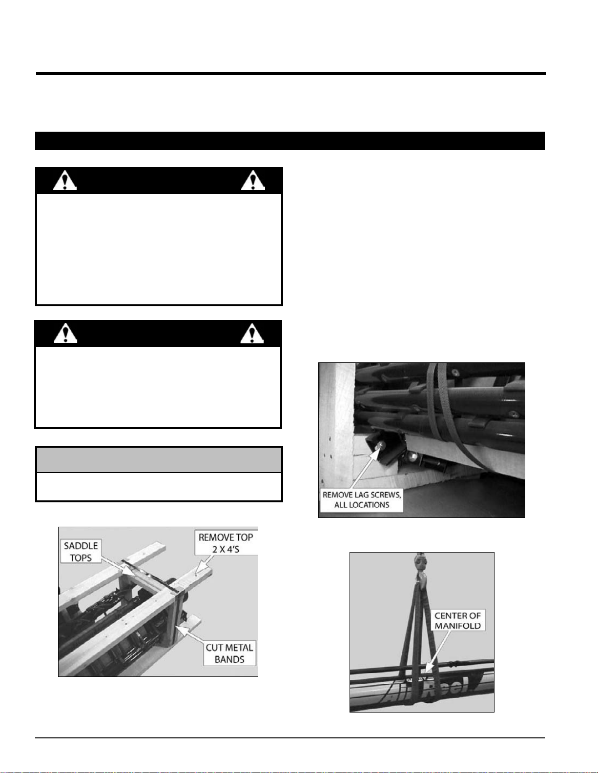
1. Cut the metal bands and remove the 2” X 4”s and saddle2. tops (Figure 1).
Remove the bat assemblies from the crate and place to3. the side.
Removethelagscrewsfromthemountingclamps(asshown4. in Figure 2) from all locations.
Using an overhead hoist and a nylon strap, sling or chain,5. connect to the center of the manifold (Figure 3).
Remove from crate, and set down on two steel sawhorses6. (or equivalent) two to four inches from the ends of the
manifold.The sawhorses must be capable of supporting 600A. pounds each.
The sawhorses must be at least 3 feet high.B.
Figure 1, Manifold and bats crate
Figure 2, Manifold and bats crate
Figure 3, Manifold and bats crate
The sawhorses must be capable of supporting 6001. pounds each.
The sawhorses must be at least 3 feet high.2. The sawhorses must be blocked, to keep the manifold3. from rolling.
WARNING
itself out during normal operation.
NOTE
Assemble in an area with sufficient space to handle1. the largest component and access to all sides of the
machine
Use only lifts, cranes and tools with sufficient capacity2. for the load.
When necessary, have someone assist you.3. Do not allow spectators in the working area.4.
WARNING

PN 12069 R072208 11
ASSEMBLY
4.2 HEADER PREPARATION
Place all controls in neutral or off, stop combine engine, set
parkingbrake,removeignitionkey, waitfor allmovingpartsto
stop,thenproperlyblockmachinebeforeservicing,adjusting,
repairing, or unplugging.
WARNING
standard fan/gearbox.
Agearbox/fanextensionkitcanbepurchasedforheaderssmaller
than 20’on combines with dual tires (See Section 4.15 for instal-
lation instructions).
PRE ‘93 HEADERS
No disassembly required.
‘93 AND AFTER HEADERS (15 FT - 22.5 FT)
shielding and set aside. These components will not be used in
reassembly.
‘93 AND AFTER HEADERS (25 FT - 30 FT)
1. shaft.
2.
3.
drive shaft.
4.
Set parts aside.All removed parts will be reused except the5.
PN 12069 R07220812
ASSEMBLY
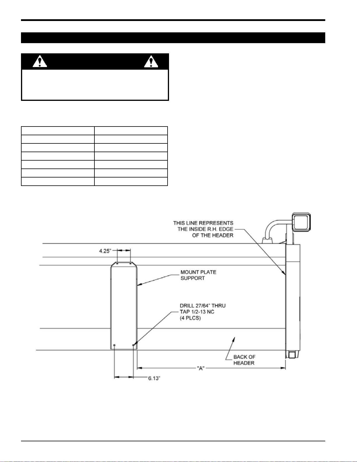
4.3 GEARBOX/FAN MOUNT - PRE 1993 SERIES
Positionthemountplatesupportonthebackoftheheaderas1. shown in Figure 4 and clamp in place. Refer to the following
table for Dimension “A.”
Markanddrillthefour27/64”(.4218”)holesandtapto1/2-132. NC for the mount plate support.
HEADER WIDTH DIM. “A”
15’ 9”
17.5’ 24”
20’ 39”
22.5’ 39”
25’ 54”
30’ 84”
Figure 4, Gearbox/fan mount dimensions (Pre 1993 series)
Attach the mount plate support to the header with four3. 1/2” x 1-1/4” serrated flange bolts and washers. Torque to
75 ft-lbs.
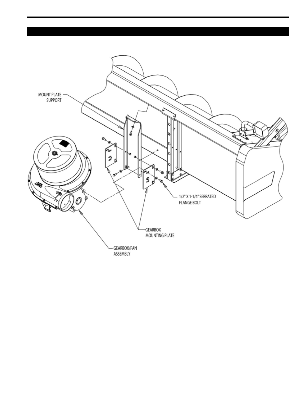
Attach gearbox mounting plates to the mount plate support4. (Figure 5) with 1/2” x 1-1/4” serrated flange bolts, washers
and nuts. Do not tighten at this time.
-5. head hoist and attach to the mounting plates with four 1/2”
bolts and washers. Do not tighten at this time.
Check the gearbox and, if necessary, fill the gearbox with6. lube before use.
equivalent with the following specifications:
7. right hand drive kit.
Place all controls in neutral or off, stop combine engine, set
parkingbrake,removeignitionkey, waitfor allmovingpartsto
stop,thenproperlyblockmachinebeforeservicing,adjusting,
repairing, or unplugging.
WARNING
PN 12069 R072208 13
ASSEMBLY
4.3 GEARBOX/FAN MOUNT - PRE 1993 SERIES
Figure 5, Gearbox/fan mount (pre 1993 series)
PN 12069 R07220814
ASSEMBLY
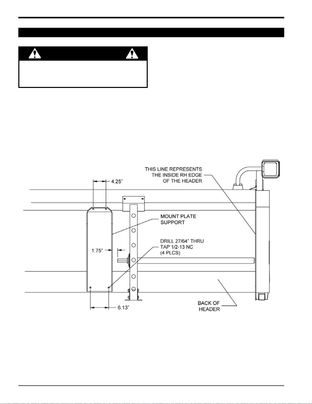
4.4 GEARBOX/FAN MOUNT - 1993/1994 SERIES (15-22.5 FT. HEADERS)
Position the mount plate support on the back of the header1. as shown in Figure 6 and clamp in place.
Mark and drill four 27/64” (.4218”) holes and tap to 1/2-132. NC for the mount plate support.
Attach the mount plate support to the header with four3. 1/2” x 1-1/4” serrated flange bolts and washers. Torque to
75 ft-lbs.
Attach gearbox mount plates to the mount plate support4. with 1/2” x 1-1/4” serrated flange bolts (Figure 7). Do not
tighten at this time.
-5. headhoistand attach to themount plates with four1/2” bolts
and washers. Do not tighten at this time.
Check the gearbox and, if necessary, fill the gearbox with6. lube before use.
equivalent with the following specifications:
7. right hand drive kit.
Figure 6, Gearbox/fan mount dimensions (1993/1994 series headers 15’-22.5’)
Place all controls in neutral or off, stop combine engine, set
parkingbrake,removeignitionkey, waitfor allmovingpartsto
stop,thenproperlyblockmachinebeforeservicing,adjusting,
repairing, or unplugging.
WARNING

PN 12069 R072208 15
ASSEMBLY
4.4 GEARBOX/FAN MOUNT - 1993/1994 SERIES (15-22.5 FT. HEADERS)
Figure 7, Gearbox/fan mount (1993/1994 series headers 15’-22.5’)

PN 12069 R07220816
ASSEMBLY
4.5 GEARBOX/FAN MOUNT - ‘95 AND LATER SERIES (15-22.5 FT. HEADERS)
Position the mount plate support on the back of the header1. as shown in Figure 8 and clamp in place.
Markanddrillthefour27/64”(.4218”)holesandtapto1/2-132. NC for the mount plate support.
Attach the mount support plate to the header with four3. 1/2” x 1-1/4” serrated flange bolts and washers. Torque to
75 ft-lbs.
Attach gearbox mounting plates to the mount plate support4. with 1/2” x 1-1/4” serrated flange bolts (Figure 9). Do not
tighten at this time.
-5. head hoist and attach to the mounting plates with four 1/2”
bolts and washers. Do not tighten at this time.
Check the gearbox and, if necessary, fill the gearbox with6. lube before use.
equivalent with the following specifications:
7. right hand drive kit.
Figure 8, Gearbox/fan mount dimensions (1995 and later headers 15’-22.5’)
Place all controls in neutral or off, stop combine engine, set
parkingbrake,removeignitionkey, waitfor allmovingpartsto
stop,thenproperlyblockmachinebeforeservicing,adjusting,
repairing, or unplugging.
WARNING
This manual suits for next models
1
Table of contents
Other Crary Farm Equipment manuals


Popular Farm Equipment manuals by other brands

Schaffert
Schaffert Rebounder Mounting instructions

Stocks AG
Stocks AG Fan Jet Pro Plus 65 Original Operating Manual and parts list

Cumberland
Cumberland Integra Feed-Link Installation and operation manual

BROWN
BROWN BDHP-1250 Owner's/operator's manual

Molon
Molon BCS operating instructions

Vaderstad
Vaderstad Rapid Series instructions


