Cray T3E User manual

HMM-369-0 Cray Research Proprietary 1
CRAY T3E AC Multiple-cabinet Installation
HMM-369-0
Record of Revision . . . . . . . . . . . . . . . . . . . . . . . . . . . . . . . . . . . . . . . . . . . 8
Overview . . . . . . . . . . . . . . . . . . . . . . . . . . . . . . . . . . . . . . . . . . . . . . . . . . . 8
Safety Information . . . . . . . . . . . . . . . . . . . . . . . . . . . . . . . . . . . . . . . . . . . . 10
Hazard Statements . . . . . . . . . . . . . . . . . . . . . . . . . . . . . . . . . . . . . . . . . 10
ESD Precautions . . . . . . . . . . . . . . . . . . . . . . . . . . . . . . . . . . . . . . . . . . 10
ESD Smock . . . . . . . . . . . . . . . . . . . . . . . . . . . . . . . . . . . . . . . . . . . 10
Wrist Strap . . . . . . . . . . . . . . . . . . . . . . . . . . . . . . . . . . . . . . . . . . . . 11
Safety Precautions . . . . . . . . . . . . . . . . . . . . . . . . . . . . . . . . . . . . . . . . . 11
Preinstallation Activities . . . . . . . . . . . . . . . . . . . . . . . . . . . . . . . . . . . . . . . 13
Tools Required . . . . . . . . . . . . . . . . . . . . . . . . . . . . . . . . . . . . . . . . . . . . 13
Checking Site Planning Requirements . . . . . . . . . . . . . . . . . . . . . . . . . . 13
Checking the Power Cord Receptacles . . . . . . . . . . . . . . . . . . . . . . . . . 14
Power Wiring for High-leakage Current . . . . . . . . . . . . . . . . . . . . . . . . 16
Unloading the Computer System . . . . . . . . . . . . . . . . . . . . . . . . . . . . . . . . . 17
Inspecting the System . . . . . . . . . . . . . . . . . . . . . . . . . . . . . . . . . . . . . . . . . 19
Opening the “OPEN FIRST” Box . . . . . . . . . . . . . . . . . . . . . . . . . . . . . . . . 20
Transporting the Mainframe to the Designated Location . . . . . . . . . . . . . . 20
Shipping Specifications . . . . . . . . . . . . . . . . . . . . . . . . . . . . . . . . . . . . . 21
Unpacking the CRAY T3E AC Cabinets . . . . . . . . . . . . . . . . . . . . . . . . . . . 22
Unpacking a Crate that Contains a Single Cabinet . . . . . . . . . . . . . . . . 22
Unpacking a Crate that Contains Two or Three Cabinets . . . . . . . . . . . 30
Unpacking and Positioning the PC-10 . . . . . . . . . . . . . . . . . . . . . . . . . . . . . 37
Unpacking and Positioning the System Workstation (SWS) . . . . . . . . . . . . 37
Unpacking and Positioning Additional System Components . . . . . . . . . . . 37
(continued)

CRAY T3E AC Multiple-cabinet Installation
2 CrayResearchProprietary HMM-369-0
Complete the following tasks when you bolt cabinets together:
Joining Two or More CRAY T3E AC Cabinets . . . . . . . . . . . . . . . . . . . . . . 38
Preparing the CRAY T3E Cabinets for Internal Wiring . . . . . . . . . . . . 38
Positioning Cabinets Temporarily When No Cabinets Are
Prejoined . . . . . . . . . . . . . . . . . . . . . . . . . . . . . . . . . . . . . . . . . . . . . 38
Positioning Cabinets Temporarily When Some Cabinets Are
Prejoined . . . . . . . . . . . . . . . . . . . . . . . . . . . . . . . . . . . . . . . . . . . . . 42
Removing Doors . . . . . . . . . . . . . . . . . . . . . . . . . . . . . . . . . . . . . . . 46
Removing the Blower Exhaust Shields . . . . . . . . . . . . . . . . . . . . . . 47
Removing Access Panels . . . . . . . . . . . . . . . . . . . . . . . . . . . . . . . . . 47
Removing Wire-duct Covers . . . . . . . . . . . . . . . . . . . . . . . . . . . . . . 49
Removing the Side Trim and Logic Panels (Optional) . . . . . . . . . . 51
Attaching Cable Troughs . . . . . . . . . . . . . . . . . . . . . . . . . . . . . . . . . 52
Joining the Cabinets . . . . . . . . . . . . . . . . . . . . . . . . . . . . . . . . . . . . . 53
Opening the Cable Ducts . . . . . . . . . . . . . . . . . . . . . . . . . . . . . . . . . 56
Grounding the Mainframe Chassis . . . . . . . . . . . . . . . . . . . . . . . . . 58
Removing Clock and Logic Modules . . . . . . . . . . . . . . . . . . . . . . . 59
Preparing the Rails for Wire Insertion . . . . . . . . . . . . . . . . . . . . . . . 62
Removing Slot Plugs . . . . . . . . . . . . . . . . . . . . . . . . . . . . . . . . . 62
Removing Rail Connectors . . . . . . . . . . . . . . . . . . . . . . . . . . . . 63
Removing Connector Pin Locks . . . . . . . . . . . . . . . . . . . . . . . . 66
Completing the Internal Wiring . . . . . . . . . . . . . . . . . . . . . . . . . . . . . . . 67
Completing the Clock Connections . . . . . . . . . . . . . . . . . . . . . . . . . 67
Completing the Boundary Scan Connections . . . . . . . . . . . . . . . . . 74
Connecting the Point-to-point Wires – 4 or More Cabinets . . . 75
Connecting 4-pin Edge-to-Pigtail Cables – P/N 15237701 . . . . 77
Connecting the Daisy Chain . . . . . . . . . . . . . . . . . . . . . . . . . . . 80
Connecting Scan Chain 0 to the Scan Master . . . . . . . . . . . . . . 82
Connecting Scan Chain 1 to the Scan Master . . . . . . . . . . . . . . 84
Reinstalling the Connectors in the Top Clock Rail . . . . . . . . . . . . . 88
Completing the Torus Interconnect Network Connections . . . . . . . 90
Closing the Cable Ducts . . . . . . . . . . . . . . . . . . . . . . . . . . . . . . . . . . . . . 93
Installing Modules . . . . . . . . . . . . . . . . . . . . . . . . . . . . . . . . . . . . . . . . . 93
Installing Side Access Panels and Trim . . . . . . . . . . . . . . . . . . . . . . . . . 95

CRAY T3E AC Multiple-cabinet Installation
HMM-369-0 Cray Research Proprietary 3
Complete the following tasks when you DO NOT bolt cabinets together:
Positioning Cabinets (for Prejoined Cabinets) . . . . . . . . . . . . . . . . . . . . . . . 97
Grounding the Mainframe Chassis (for Prejoined Cabinets) . . . . . . . . . . . . 100
Installing the Cabinet Side Panels (for Prejoined Cabinets) . . . . . . . . . . . . 101
Complete the following tasks for ALL cabinets:
Verifying the CRAY T3E AC Hardware . . . . . . . . . . . . . . . . . . . . . . . . . . . 103
Verifying the Voltage Selector Switch . . . . . . . . . . . . . . . . . . . . . . . . . . 104
Connecting the Optional Customer Alarm . . . . . . . . . . . . . . . . . . . . . . 105
Verifying the Control System Hardware . . . . . . . . . . . . . . . . . . . . . . . . 108
Verifying Additional Power Hardware . . . . . . . . . . . . . . . . . . . . . . . . . 110
Verifying that the Modules Are Seated and Cammed . . . . . . . . . . . . . . 111
Completing the System Cabling . . . . . . . . . . . . . . . . . . . . . . . . . . . . . . . . . 112
Cable Labels . . . . . . . . . . . . . . . . . . . . . . . . . . . . . . . . . . . . . . . . . . . . . . 113
Connecting the WACS . . . . . . . . . . . . . . . . . . . . . . . . . . . . . . . . . . . . . . 114
Connecting the GigaRing Cables . . . . . . . . . . . . . . . . . . . . . . . . . . . . . . 115
Verifying System Cabling . . . . . . . . . . . . . . . . . . . . . . . . . . . . . . . . . . . 119
Powering Up the System Workstation (SWS) . . . . . . . . . . . . . . . . . . . . . . . 119
Powering Up the PC-10 . . . . . . . . . . . . . . . . . . . . . . . . . . . . . . . . . . . . . . . . 119
Connecting the Input Power to the CRAY T3E Cabinets . . . . . . . . . . . . . . 119
Verifying Cabinet Operation . . . . . . . . . . . . . . . . . . . . . . . . . . . . . . . . . . . . 120
Verifying WACS Control . . . . . . . . . . . . . . . . . . . . . . . . . . . . . . . . . . . . 120
Verifying Operation of the Blower . . . . . . . . . . . . . . . . . . . . . . . . . . . . . 121
Verifying Operation of the Thermistors . . . . . . . . . . . . . . . . . . . . . . . . . 121
Verifying Cabinet Power Switch and Shunt Trip Operation . . . . . . . . . 121
Verifying Remote Alarm Operation (Optional) . . . . . . . . . . . . . . . . . . . 122
Powering Up the Modules . . . . . . . . . . . . . . . . . . . . . . . . . . . . . . . . . . . . . . 122
Verifying Remote Power On/Off . . . . . . . . . . . . . . . . . . . . . . . . . . . . . . . . . 123
Running Boundary Scan and Diagnostics . . . . . . . . . . . . . . . . . . . . . . . . . . 124
Installing Panels and Doors . . . . . . . . . . . . . . . . . . . . . . . . . . . . . . . . . . . . . 131
Installing Rear Access Panels . . . . . . . . . . . . . . . . . . . . . . . . . . . . . . . . 131
Installing the Doors . . . . . . . . . . . . . . . . . . . . . . . . . . . . . . . . . . . . . . . . 132
Appendix – Wire Removal . . . . . . . . . . . . . . . . . . . . . . . . . . . . . . . . . . . . 133

CRAY T3E AC Multiple-cabinet Installation
4 CrayResearchProprietary HMM-369-0
Figures
Figure 1. Power Plugs and Receptacles . . . . . . . . . . . . . . . . . . . . . . . . . 16
Figure 2. Single-cabinet Shipping Configuration . . . . . . . . . . . . . . . . . . 18
Figure 3. Three-cabinet Shipping Configuration . . . . . . . . . . . . . . . . . . 19
Figure 4. Cabinet Shipping Crate . . . . . . . . . . . . . . . . . . . . . . . . . . . . . . 23
Figure 5. Retaining Block and Screws . . . . . . . . . . . . . . . . . . . . . . . . . . 24
Figure 6. Installing the Ramp . . . . . . . . . . . . . . . . . . . . . . . . . . . . . . . . . 25
Figure 7. Cardboard Shipping Container . . . . . . . . . . . . . . . . . . . . . . . . 26
Figure 8. Removing the Inside Retaining Bar . . . . . . . . . . . . . . . . . . . . 27
Figure 9. Shipping Bolts . . . . . . . . . . . . . . . . . . . . . . . . . . . . . . . . . . . . . 28
Figure 10. Remove the Blocks . . . . . . . . . . . . . . . . . . . . . . . . . . . . . . . . . 31
Figure 11. Remove the Bumpers . . . . . . . . . . . . . . . . . . . . . . . . . . . . . . . . 31
Figure 12. Place the Blocks beneath the Corner Levelers . . . . . . . . . . . . 32
Figure 13. Lower the Cabinets onto the Blocks and Remove the Lifts . . 32
Figure 14. Remove the Straps . . . . . . . . . . . . . . . . . . . . . . . . . . . . . . . . . . 33
Figure 15. Remove the Cardboard Lid and Panels . . . . . . . . . . . . . . . . . . 33
Figure 16. Remove the Four Shipping Bolts . . . . . . . . . . . . . . . . . . . . . . . 34
Figure 17. Remove the Pallet . . . . . . . . . . . . . . . . . . . . . . . . . . . . . . . . . . 34
Figure 18. Remove the Blocks . . . . . . . . . . . . . . . . . . . . . . . . . . . . . . . . . 35
Figure 19. Lower the Cabinets to the Floor . . . . . . . . . . . . . . . . . . . . . . . 35
Figure 20. CRAY T3E AC Cabinet Layout . . . . . . . . . . . . . . . . . . . . . . . 38
Figure 21. Door Latches and Handle (Front Door) . . . . . . . . . . . . . . . . . . 39
Figure 22. Cabinet Floor Plan . . . . . . . . . . . . . . . . . . . . . . . . . . . . . . . . . . 40
Figure 23. Temporary Cabinet Positions . . . . . . . . . . . . . . . . . . . . . . . . . 41
Figure 24. CRAY T3E AC Cabinet Layout . . . . . . . . . . . . . . . . . . . . . . . 42
Figure 25. Door Latches and Handle (Front Door) . . . . . . . . . . . . . . . . . . 43
Figure 26. Cabinet Floor Plan . . . . . . . . . . . . . . . . . . . . . . . . . . . . . . . . . . 44
Figure 27. Temporary Cabinet Positions for Prejoined Cabinets . . . . . . . 45
Figure 28. Access Panel Locations . . . . . . . . . . . . . . . . . . . . . . . . . . . . . . 48
Figure 29. Frame-bolt Holes and Wire-duct Locations . . . . . . . . . . . . . . 50
Figure 30. Cable Troughs . . . . . . . . . . . . . . . . . . . . . . . . . . . . . . . . . . . . . 52

CRAY T3E AC Multiple-cabinet Installation
HMM-369-0 Cray Research Proprietary 5
Figure 31. Six-cabinet System . . . . . . . . . . . . . . . . . . . . . . . . . . . . . . . . . 53
Figure 32. Frame-joiner Bolt Locations . . . . . . . . . . . . . . . . . . . . . . . . . . 54
Figure 33. Frame-joiner Bolts . . . . . . . . . . . . . . . . . . . . . . . . . . . . . . . . . . 55
Figure 34. Intercabinet Cable Duct Locations . . . . . . . . . . . . . . . . . . . . . 56
Figure 35. Intercabinet Cable Duct (as viewed from inside cabinet) . . . . 57
Figure 36. Chassis Ground Connections (Rear View of Cabinet) . . . . . . 58
Figure 37. Module Camming . . . . . . . . . . . . . . . . . . . . . . . . . . . . . . . . . . 59
Figure 38. Module Setscrew Locations (Rear View of Cabinet) . . . . . . . 61
Figure 39. Removing Plugs from the Top Clock Rail . . . . . . . . . . . . . . . . 62
Figure 40. Loosening the Wires . . . . . . . . . . . . . . . . . . . . . . . . . . . . . . . . 63
Figure 41. Clock Connector Locations . . . . . . . . . . . . . . . . . . . . . . . . . . . 64
Figure 42. Removing Clock Rail Connectors . . . . . . . . . . . . . . . . . . . . . . 64
Figure 43. Connector Locations – Bottom Clock Rail . . . . . . . . . . . . . . . 65
Figure 44. Removing a Connector Spring . . . . . . . . . . . . . . . . . . . . . . . . 65
Figure 45. Removing a Connector Pin Lock . . . . . . . . . . . . . . . . . . . . . . 66
Figure 46. Example – Clock Wire Labels . . . . . . . . . . . . . . . . . . . . . . . . . 68
Figure 47. Clock Connections . . . . . . . . . . . . . . . . . . . . . . . . . . . . . . . . . . 69
Figure 48. System and GigaRing Clock Wire Connections . . . . . . . . . . . 69
Figure 49. Pin Locations . . . . . . . . . . . . . . . . . . . . . . . . . . . . . . . . . . . . . . 71
Figure 50. 2-pin Connector Position . . . . . . . . . . . . . . . . . . . . . . . . . . . . . 72
Figure 51. Wire Insertion . . . . . . . . . . . . . . . . . . . . . . . . . . . . . . . . . . . . . 72
Figure 52. Wire Insertion with Wire Rod . . . . . . . . . . . . . . . . . . . . . . . . . 73
Figure 53. Edge-to-edge Connection – P/N 15224009 . . . . . . . . . . . . . . . 75
Figure 54. Edge-to-edge Connection – P/N 15223701 . . . . . . . . . . . . . . . 75
Figure 55. Direct Boundary Scan Connections . . . . . . . . . . . . . . . . . . . . . 76
Figure 56. 4-pin Edge-to-pigtail Connections . . . . . . . . . . . . . . . . . . . . . 78
Figure 57. 4-pin Edge-to-Pigtail Cable – P/N 15237701 . . . . . . . . . . . . . 79
Figure 58. TDOM > TDIM Daisy Chain Connection - Between Cabinets 80
Figure 59. Scan Jumper/Intermediate Connection – P/N 15223802 . . . . . 81
Figure 60. Connection – Scan Master to End of Daisy Chain –
Scan Chain 0 . . . . . . . . . . . . . . . . . . . . . . . . . . . . . . . . . . . . . . 82
Figure 61. 2-position Socket, Edge-to-Pigtail Cable – P/N 15237601 . . . 83

CRAY T3E AC Multiple-cabinet Installation
6 CrayResearchProprietary HMM-369-0
Figure 62. Boundary Scan Connections to Cabinet 3, Slot 1 . . . . . . . . . . 84
Figure 63. Scan Jumper/Intermediate Connection – P/N 15223802 . . . . . 85
Figure 64. 2-position Pin, Edge-to-Pigtail Cable – P/N 15237801 . . . . . . 86
Figure 65. 2-position Socket, Edge-to-Pigtail Cable – P/N 15237601 . . . 87
Figure 66. Inserting and Seating a Plastic Connector Pin Lock . . . . . . . . 88
Figure 67. Example of Torus Connections . . . . . . . . . . . . . . . . . . . . . . . . 90
Figure 68. Connectors P2 and P3 – Torus Cable Assembly . . . . . . . . . . . 91
Figure 69. Module Camming . . . . . . . . . . . . . . . . . . . . . . . . . . . . . . . . . . 94
Figure 70. Installing the Side Panels . . . . . . . . . . . . . . . . . . . . . . . . . . . . . 96
Figure 71. CRAY T3E AC Cabinet Layout . . . . . . . . . . . . . . . . . . . . . . . 97
Figure 72. Door Latches and Handle (Front Door) . . . . . . . . . . . . . . . . . . 98
Figure 73. Cabinet Floor Plan . . . . . . . . . . . . . . . . . . . . . . . . . . . . . . . . . . 99
Figure 74. Chassis Ground Connections (Rear View of Cabinet) . . . . . . 100
Figure 75. Installing Side Panels . . . . . . . . . . . . . . . . . . . . . . . . . . . . . . . 102
Figure 76. CRAY T3E Cabinet Components -- Front View . . . . . . . . . . . 103
Figure 77. Voltage Selector Switch (SW1) . . . . . . . . . . . . . . . . . . . . . . . . 104
Figure 78. Power-cord Cover and Power-box Cover (Removed) . . . . . . . 105
Figure 79. Filter Bracket . . . . . . . . . . . . . . . . . . . . . . . . . . . . . . . . . . . . . . 106
Figure 80. Remote Alarm Contacts - Locations . . . . . . . . . . . . . . . . . . . . 107
Figure 81. WACS Front Panel . . . . . . . . . . . . . . . . . . . . . . . . . . . . . . . . . . 108
Figure 82. WACS with Front Panel Open . . . . . . . . . . . . . . . . . . . . . . . . . 109
Figure 83. Power Supply Rack . . . . . . . . . . . . . . . . . . . . . . . . . . . . . . . . . 110
Figure 84. Module Setscrew Locations (Rear View of Cabinet) . . . . . . . 111
Figure 85. Typical System - Block Diagram . . . . . . . . . . . . . . . . . . . . . . . 112
Figure 86. WACS Connector Location on I/O Bulkhead . . . . . . . . . . . . . 114
Figure 87. I/O Bulkhead – Connector Locations . . . . . . . . . . . . . . . . . . . 115
Figure 88. Example GigaRing Connections . . . . . . . . . . . . . . . . . . . . . . . 116
Figure 89. GigaRing Connectors on PC-10 (Rear View) . . . . . . . . . . . . . 117
Figure 90. NSR-1 GigaRing Connectors . . . . . . . . . . . . . . . . . . . . . . . . . 118
Figure 91. MPN-1 GigaRing Connectors . . . . . . . . . . . . . . . . . . . . . . . . . 118
Figure 92. WACS Summary Screen - Standby Mode . . . . . . . . . . . . . . . . 120

CRAY T3E AC Multiple-cabinet Installation
HMM-369-0 Cray Research Proprietary 7
Figure 93. Power Supply Circuit Breakers and LEDs . . . . . . . . . . . . . . . 123
Figure 94. T3EMS Main Window . . . . . . . . . . . . . . . . . . . . . . . . . . . . . . 125
Figure 95. T3EMS Scan Tool Options Window . . . . . . . . . . . . . . . . . . . . 126
Figure 96. Load Program Window . . . . . . . . . . . . . . . . . . . . . . . . . . . . . . 127
Figure 97. PE Configuration Window . . . . . . . . . . . . . . . . . . . . . . . . . . . . 128
Figure 98. Access Panel Locations . . . . . . . . . . . . . . . . . . . . . . . . . . . . . . 131
Figure 99. Connector Removal with Mechanical Pencil . . . . . . . . . . . . . 133
Tables
Table 1. Required Power Receptacle Test Readings . . . . . . . . . . . . . . . 15
Table 2. Remote Alarm Contacts - Descriptions . . . . . . . . . . . . . . . . . . 107
Table 3. Bottom Scanner DIP Switch Functions . . . . . . . . . . . . . . . . . . 109
Table 4. Cable Labels . . . . . . . . . . . . . . . . . . . . . . . . . . . . . . . . . . . . . . 113
Table 5. Example Cable Label . . . . . . . . . . . . . . . . . . . . . . . . . . . . . . . 113
Table 6. CRAY T3E AC I/O Bulkhead GigaRing Connections . . . . . . 115
Table 7. Offline Diagnostic Tests . . . . . . . . . . . . . . . . . . . . . . . . . . . . . 130

Record of Revision CRAY T3E AC Multiple-cabinet Installation
8 CrayResearchProprietary HMM-369-0
Record of Revision
Revision 0: October 1996
Original printing.
Overview
These installation procedures are intended to assist Cray Research personnel
with the mechanical installation of 2 or more CRAY T3E air-cooled (AC)
cabinets. The installation includes the following tasks:
•Unpacking and positioning the system components
•Connecting cables
•Powering on the system and verifying operation
•Verifying system function with diagnostics
This document provides an efficient sequence for the installation. You may
deviate from the sequence as required; however, when possible, perform the
procedures in the order shown.
Cray Research ships CRAY T3E AC cabinets in three shipping configurations:
1 cabinet per shipping crate, 2 cabinets per crate, and 3 cabinets per crate. When
a crate contains 2 or 3 cabinets, the cabinets are bolted together and the wires
that pass between cabinets are connected.
As a result of these variable shipping configurations, you may not be required
to complete internal cabinet wiring. For example:
•If your system contains 2 or 3 cabinets, and the cabinets are bolted
together during shipment, then you do not need to complete internal
cabinet wiring.
•If your system contains 4 or more cabinets, or if you must otherwise bolt
cabinets together, then you must complete internal cabinet wiring.
Your system configuration and site access restrictions determine how your
system ships.
NOTE: This document uses the term prejoined to refer to cabinets that are
bolted together during shipment.
This document does not contain troubleshooting procedures, nor does it contain
installation procedures for peripheral equipment.

CRAY T3E AC Multiple-cabinet Installation Overview
HMM-369-0 Cray Research Proprietary 9
For information on the PC-10 installation, refer to Peripheral Cabinet (PC-10)
Installation, publication HMM-371. For information on the SWS installation,
refer to System Workstation, publication HMM-222.
For information on the CRAY T3E software installation, refer to the CRAY T3E
Software Installation and Configuration Guide, publication SG-2610. For
information on a single-cabinet installation, refer to CRAY T3E AC
Single-cabinet Installation Procedures, HMM-164.
Installationpersonnel shouldhaveabasicknowledgeof computersystem power
processes. They should also have a basic understanding of the control system,
the layout of the various cabinet components, and of running offline diagnostics.
The installation coordinator is responsible for CRUISE (Cray Research Unified
System Enterprise) registration and for installation reporting. The system log
book in the “OPEN FIRST” box contains a copy of the Web-based Installation
Reporting tool. You may use the paper copy to help track the installation and,
if necessary, to fax the information.

Safety Information CRAY T3E AC Multiple-cabinet Installation
10 CrayResearchProprietary HMM-369-0
Safety Information
The following subsections contain important safety information that you must
read and understand before you begin the CRAY T3E AC system installation.
Hazard Statements
During the installation of the computer system, be alert for hazard advisory
statements. The following list describes the hazard statement signal words:
•Danger indicates an imminently hazardous situation that, if not avoided,
will result in death or serious injury.
•Warning indicates a potentially hazardous situation that, if not avoided,
could result in death or serious injury.
•Caution indicates a potentially hazardous situation that, if not avoided,
may result in minor or moderate injury. This signal word is also used to
alert personnel against unsafe practices that can result in equipment
damage and/or data corruption.
ESD Precautions
Observe electrostatic discharge (ESD) precautions during the entire installation
process. Required apparel includes an ESD smock and an ESD wrist strap.
ESD Smock
Wear a Cray Research-approved static-dissipative smock when servicing or
handling an ESD-sensitive device. Completely button the smock and wear it as
the outermost layer of clothing. You must have a portion of the smock’s sleeves
in direct contact with the skin of your arms. Skin contact is essential for a
dissipativepath-to-earth groundthrough yourwriststrap. Tuck hairthatexceeds
shoulder length inside the back of the smock.
CAUTION
Observe all ESD precautions. Failure to
do so could result in damage to the
equipment.
CRAY T3E AC Multiple-cabinet Installation Safety Information
HMM-369-0 Cray Research Proprietary 11
Wrist Strap
Wear a Cray Research-approved wrist strap when servicing or handling an
ESD-sensitive device to eliminate possible ESD damage to equipment. Connect
the wrist strap cord directly to earth ground.
NOTE: The CRAY T3E AC cabinet contains two sets of jacks (front and
rear) for a mating ESD ground strap.
Safety Precautions
Beforeyouperformtheproceduresinthisdocument,takeafewminutestoreview
the Safety and ESD Guidelines, publication number HGM-016. In addition,
observethefollowingsafetymeasureswheninstalling,repairing,ormaintaining
the system.
•Use caution when removing the cabinets from the ramps. Moving these
cabinets can cause personal injury or property damage if the cabinets are
not handled properly.
•Ensure that the cabinet crates are positioned close to their final positions
before you unpack them.
•Do not move the cabinets while they are connected to power.
•Do not wear watches or jewelry when you work on a CRAY T3E system
cabinet.
•Keep fingers and conductive tools away from high-voltage areasand from
high-current areas.
•Ensure that a qualified electrician has properly installed the power
receptacles.
DANGER
Keep fingers and conductive tools away
from high-voltage areas. Serious injury
or death will occur if these precautions
are not followed.

Safety Information CRAY T3E AC Multiple-cabinet Installation
12 CrayResearchProprietary HMM-369-0
•Set all circuit breakers to the OFF (0) position before you plug in the
system power cord.
•Unplug, lock, and tag the cabinet power plug before you work on the
power system components.
•Remove all tools from the system cabinets after you service them.
•Replace all covers and panels that you removed from the system during
servicing.
•Power off the system only after the system software has been shut down
in an orderly manner.
DANGER
Unplug, lock, and tag the AC cord.
Failure to do so will result in damage to
the equipment and serious injury or
death to the maintenance person.
CAUTION
If you power off the system before you halt the
operatingsystem,youmaylose system and customer
files (data).

CRAY T3E AC Multiple-cabinet Installation Preinstallation Activities
HMM-369-0 Cray Research Proprietary 13
Preinstallation Activities
Before you install your system, read the following subsections and verify that
your site meets all site requirements.
Tools Required
Ensure that you have the following tools, which are necessary to complete the
hardware installation. These tools are available from Cray Research’s Customer
Service Logistics department or from any hand-tool vendor. (The Logistics part
number for the CRAY T3E tool kit is 57247800.)
•Multimeter
•Cutters
•Adjustable wrench or 11-mm, 15-mm, and 16-mm wrenches
•0.5-in., 3-mm, and 4-mm hex (Allen) wrenches with driver
•#1 and #2 Phillips screwdrivers
•Small and medium flatblade screwdrivers
•Flashlight
•Heat gun (optional)
•Wiring tools (if you must join cabinets), including:
•0.3-mm mechanical pencil, with no lead (or a wire removal tool)
•Dental pick
•Hemostats, tweezers, or wire insertion tool (all optional)
Checking Site Planning Requirements
Before you install your CRAY T3E system, ensure that your site meets all of the
site planning requirements included in Preparing for a CRAY T3E Air-cooled
SystemInstallation,CrayResearchpublicationnumberHR-04118.Forexample,
take some time to verify the following things:
•Verify that the site has appropriate means (pallet jacks, etc.) for unloading
and transporting the system components.
•Verify that the route to the computer room is free of obstacles.
•Verify that the computer room floor is prepared according to the floor
layout diagram for the system.
•Verify that floor cutouts are complete, correct, and free of sharp edges and
burrs.
Preinstallation Activities CRAY T3E AC Multiple-cabinet Installation
14 CrayResearchProprietary HMM-369-0
•Verify that all electrical services meet site planning specifications.
•Verify that the air-conditioning equipment meets site planning
specifications.
•Verify that the ground clamps (for grounding the cabinets to the floor
grid) are in the correct locations (near the floor cutouts for I/O cables).
Checking the Power Cord Receptacles
Ensure that a qualified electrician installed the correct power receptacles
accordingto siteplanning specifications.Then CrayResearch-trainedpersonnel
should use the following procedure to ensure that the power receptacles are
properly wired. Refer to Figure 1 for drawings of the 3-phase power plugs and
receptacles that are available for CRAY T3E AC cabinets.
Performthefollowingprocedureforeachpowercordreceptaclethatwillsupport
a CRAY T3E AC cabinet:
1. Turn off, lock, and tag the customer’s circuit breaker(s) that control power
for the CRAY T3E AC cabinet power receptacle before you perform
Step 2 and Step 3.
2. Set the multimeter to a low-resistance setting.
3. Measure between the power receptacle ground-post hole and an
appropriate earth-ground location and ensure that resistance is less than
1 ohm. Figure 1 shows the post hole locations. (Appropriate earth-ground
locations could include the floor grid, a metal case receptacle, and a
circuit breaker shell.)
4. Remove the lock and tag and restore power through the customer’s circuit
breaker(s).
5. Set the multimeter to a high AC-voltage range.
DANGER
Ensure that the electrical circuit
breakers for the power receptacle being
checked are off, locked, and tagged.
Failure to do so could result in severe
shock and burns.

CRAY T3E AC Multiple-cabinet Installation Preinstallation Activities
HMM-369-0 Cray Research Proprietary 15
6. Measure between the ground-post hole and an appropriate earth-ground
location. If you detect voltage on the ground-post hole, contact a
site-approved electrician. Do not proceed with the installation.
NOTE: The ground wire may act as an antenna and, through
impedance, generate a low voltage (usually less than 1 Vac).
This is normal.
7. Perform voltage checks between the posts listed in Table 1. Refer again to
Figure 1, which shows the post locations.
Table 1. Required Power Receptacle Test Readings
Cord Assembly From Post To Post Meter Reading
P/N 57181600
60 A, 250 Vac
(4-post cord
[delta] used
commonly in
North America
and Japan)
L1 G Not to exceed 140 Vac
L2 G Not to exceed 140 Vac
L3 G Not to exceed 140 Vac
L1 L2 Between 180 and 240 Vac
L2 L3 Between 180 and 240 Vac
L1 L3 Between 180 and 240 Vac
P/N 57181700
32 A, 400 Vac
(5-post cord
[wye] used
commonly in
Europe)
L1 N Not to exceed 260 Vac
L2 N Not to exceed 260 Vac
L3 N Not to exceed 260 Vac
L1 L2 Between 360 and 440 Vac
L2 L3 Between 360 and 440 Vac
L1 L3 Between 360 and 440 Vac

Preinstallation Activities CRAY T3E AC Multiple-cabinet Installation
16 CrayResearchProprietary HMM-369-0
Figure 1. Power Plugs and Receptacles
Power Wiring for High-leakage Current
Please note the following statement by Underwriters Laboratories, Inc.
An insulated earthing conductor that is identical in size, insulation material, and
thickness to the earthed and unearthed branch-circuit supply conductors except
that it is green with or without one or more yellow stripes is to be installed as
partof thebranch circuitthatsuppliestheunitorsystem.Theearthingconductor
described is to be connected to earth at the service equipment or, if supplied by
a separately derived system, at the supply transformer or motor-generator
(UL 60 95).
L1
L2 L3
N
L2
L3
4-post (~250 Vac) Power
Plug and Receptacles
L1
Ground
L3
L2 L2
Ground
Ground
L1
N
L3
N
L1
Ground
5-post (400 Vac) Power
Plug and Receptacles
L2

CRAY T3E AC Multiple-cabinet Installation Unloading the Computer System
HMM-369-0 Cray Research Proprietary 17
Unloading the Computer System
Cray Research ships CRAY T3E AC cabinets in three shipping configurations:
1 cabinet per shipping crate, 2 cabinets per crate, and 3 cabinets per crate. Your
configuration and site access restrictions determine how your system ships.
If your system includes 1 or more cabinets that ship singly (1 cabinet per crate),
the side panels are installed on the single cabinet(s). If your system does not
include a cabinet that ships singly, then the side panels ship in separate boxes.
Figure 2 shows the CRAY T3E AC single-cabinet shipping configuration, lift
openings, and dimensions. Figure 3 shows the CRAY T3E AC 3-cabinet
shipping configuration, lift openings, and dimensions. The 2-cabinet shipping
configuration is a smaller version of the 3-cabinet configuration.
In most cases, if your loading dock is the same height as the transportation
vehicle, you may use ROL-A-LIFTs or pallet jacks to unload the system from
the transportation vehicle. Specifically, you may use a pallet jack to unload a
shipping crate that contains only 1 cabinet, and you must use ROL-A-LIFTs to
unload shipping crates that contains 2 or 3 cabinets.
When you use ROL-A-LIFTs, position the ROL-A-LIFTs on the ends of the
shippingcrateas shown in Figure 3.Ensurethat you place aboardbetween each
ROL-A-LIFT and the side of the shipping crate as shown in Figure 3; position
theboard 35 to40 in.(889to 1,016mm)from thetopof theshipping crate. (Two
2 in. x4 in. boards are supplied with each crate that contains 2 or 3 cabinets; the
boards are strapped to the outside of the crate.)
NOTE: You will use the ROL-A-LIFTs when you unpack crates that
contain 2 or 3 cabinets.
If the loading dock is not level with the vehicle, you must provide a forklift or
anotherapprovedmethod to unload thesystem.A platform or rampmaybe used
to obtain the desired level as long as the ramp does not exceed a ratio of 1 unit
vertical to 6 units horizontal. Refer to Preparing for a CRAY T3E Air-cooled
System Installation, publication HR-04118, for more information on site
requirements.
CAUTION
Prevent computer equipment from
rolling off the transportation vehicle.
Failure to do so could result in serious
damage to the computer equipment.

Unloading the Computer System CRAY T3E AC Multiple-cabinet Installation
18 CrayResearchProprietary HMM-369-0
Ifthecomputersitedoesnothavealoadingdock,arrangeforaforklifttoremove
the computer from the transportation vehicle.
Ensurethatatleasttwopeopleareavailabletohelpmovethemainframecabinets.
(We recommend that four or more people help move crates that contain 2 or 3
cabinets.) Perform all movement of the cabinets slowly and carefully. Follow
any instructions that are printed on the packing crates.
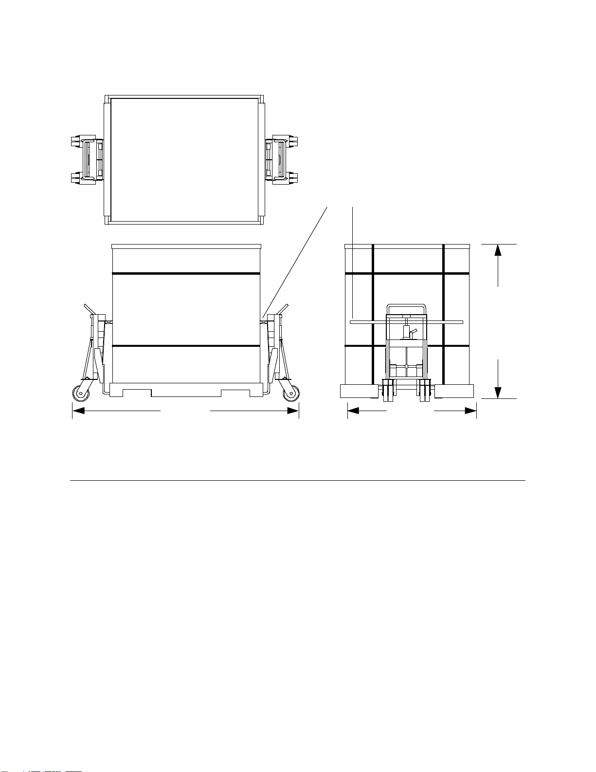
Figure 2. Single-cabinet Shipping Configuration
CRAY T3E AC Multiple-cabinet Installation Inspecting the System
HMM-369-0 Cray Research Proprietary 19
Figure 3. Three-cabinet Shipping Configuration
Inspecting the System
Theshippingcratescontainthemainframecabinets,PC-10,systemworkstation,
additional system components, and system maintenance and user
documentation. After the system is unloaded from the truck, perform the
following steps before you transport and unpack it.
1. Ensure that the boxes arrived unopened. If any boxes are open, identify
and record the opened boxes through the CRUISE system.
2. Inspect the shipping crate for signs of external damage such as dents,
holes, crushed corners, and water marks. Record any signs of external
damage as an installation defect through the CRUISE system.
Later, when you unpack the system, check the contents of each shipping crate
against the packing list, which is attached to the outside of the shipping crate.
112.5 in.
(2,858 mm)
76.5 in.
(1,943mm)
Rolling
Height
63.75 in.
(1,619 mm)
NOTE: The side panels
are shipped separately.
Board(35to40 in. [889to1,016mm]
from top of shipping crate)

Opening the “OPEN FIRST” Box CRAY T3E AC Multiple-cabinet Installation
20 CrayResearchProprietary HMM-369-0
Opening the “OPEN FIRST” Box
Afteryouinspecttheshippingcratesandboxesfordamage,opentheboxmarked
“OPEN FIRST.” This box contains up-to-date versions of this document and
associated installation documents. This box also includes the following
documents that you will refer to during the installation:
•System configuration documentation
•System deviation documentation
•Cable list
To ensure that you have the most accurate information available, use the
installationdocumentsfromthe“OPENFIRST”boxtocompletetheinstallation.
Transporting the Mainframe to the Designated Location
The method you use to move the CRAY T3E AC cabinets depends on the
shipping configuration. This section provides general guidelines. In addition,
follow any instructions that are printed on the packing crates.
Youmayusethefollowingmethodstotransporteachshippingcratethatcontains
1 CRAY T3E cabinet:
•One pallet jack on the side of the crate
•One long pallet jack (approx. 60 in. [152 cm]) on the end of the crate
•Two pallet jacks (one at each end of the crate) – short distances only
Youmayusethefollowingmethodstotransporteachshippingcratethatcontains
2 CRAY T3E cabinets:
•ROL-A-LIFTs at each end of the crate (refer again to Figure 3)
•One pallet jack on the side of the crate – short distances only
Foreachpalletthatcontains3CRAYT3Ecabinets,youmustuseROL-A-LIFTs
(positioned on the ends of the crate) to transport the cabinets.
Cray Research recommends that you leave each system cabinet in its shipping
crate until it reaches its final location. If the crate does not fit through the
planned access route, you may partially disassemble the crate.
Other manuals for T3E
2
Table of contents
Other Cray Industrial Equipment manuals


